Cad 3D Category

Mastering ArchiCAD: How to Split Morphs for Superior 3D CAD Design

Sunday, August 23, 2026

ArchiCAD’s Morph Tool offers unmatched freedom when creating custom architectural elements, complex shapes, or conceptual geometry. However, working with intricate forms can sometimes feel overwhelming if you do not know how to manipulate them efficiently. Learning how to split a morph is an essential technique for anyone looking to refine their digital modeling workflow within modern 3D CAD environments.

Why Split Morphs in ArchiCAD?

When designing unique architectural features, a single morph object can quickly become difficult to edit as its complexity grows. By splitting a morph, you divide a complex shape into smaller, independent pieces.

This method enables you to shape any morph into a better, more precise form without affecting the entire model. Whether you need to apply different materials to specific sections, adjust unique angles, or create custom geometric cutouts, splitting gives you granular control over your design. Furthermore, breaking down complex geometry helps optimize model performance within your 3D CAD project.

Simple Steps to Split a Morph

Manipulating morphs in ArchiCAD is straightforward once you know the right procedure. Here is how you can easily split any morph:

  1. Select the Morph: In either the 3D window or the 2D floor plan view, select the morph object you wish to divide.
  2. Activate the Split Tool: Choose the Split tool (represented by the axe icon) from the editing toolbar.
  3. Draw the Splitting Line/Plane: Click to define the line or plane along which you want to cut through the morph geometry.
  4. Select the Element to Retain: Click on either side of the splitting line to complete the operation.

Once split, each portion becomes an individual morph element that can be further stretched, rotated, or sculpted independently.

Elevate Your Architectural Workflow

Mastering basic geometric manipulation is what separates novice modelers from efficient BIM professionals. Utilizing the split function allows you to seamlessly edit custom organic forms, roof structures, and detailed interior elements without starting from scratch.

By taking control of your geometry with this quick technique, you can elevate your modeling capabilities, save valuable time, and achieve a smoother, more flexible 3D CAD design workflow in ArchiCAD. Start applying this method to your project today to shape your ideas into perfection!

3D CAD
Continue Reading | ความคิดเห็น

Speed Up Your 3D CAD Workflow: Vectorworks Fillet and Chamfer Guide

When designing complex objects or architectural elements, the secret to realism often lies in the details. Hard, razor-sharp edges rarely exist in the real world. That is where mastering edge-refinement tools becomes essential. If you are looking to elevate your 3D CAD modeling efficiency, understanding how to effectively use the 3D Fillet and Chamfer tools in Vectorworks is a game-changer.

What Are Fillet and Chamfer Tools?

In digital drafting, Fillet and Chamfer tools allow designers to quickly modify the sharp intersections of 3D solids:

  • 3D Fillet Tool: Rounds off sharp edges with a specified radius, creating smooth, curved transitions that mimic natural manufactured surfaces.
  • 3D Chamfer Tool: Cuts away an edge at a designated angle and distance, creating a clean, beveled slope.

Using these tools not only makes your digital models look significantly more realistic during rendering but also ensures accuracy for manufacturing and structural planning.

Quick Steps to Master Fillet and Chamfering in Vectorworks

To streamline your process in Vectorworks, follow these simple best practices:

  1. Select the Right Tool: Navigate to the 3D Modeling tool set and choose either the Fillet Edge or Chamfer Edge tool.
  2. Set Your Parameters: Before clicking on your model, enter your desired radius (for fillets) or setback distance (for chamfers) in the Tool bar settings.
  3. Select Edges Precisely: You can click individual edges, shift-click to select multiple edges, or choose entire faces to modify all surrounding edges simultaneously.
  4. Perform Non-Destructive Edits: Vectorworks maintains a parametric history. If you need to adjust the radius or distance later, simply double-click the object to edit the feature without starting from scratch.

Why These Tools Matter for Your 3D CAD Workflow

Integrating these quick modeling techniques into your daily routine drastically cuts down design time. Instead of manually constructing complex swept solids or subtractive shapes, a few clicks with the Fillet or Chamfer tools yield professional results instantly. Modern 3D CAD software relies on these intuitive operations to help designers focus on creativity rather than tedious geometry creation.

By incorporating these Vectorworks quick tips into your project routine, you will build cleaner models, render more realistic lighting, and deliver top-notch design presentations in a fraction of the time.

3D CAD
Continue Reading | ความคิดเห็น

The Ultimate Guide to 3D CAD for Precision CNC Manufacturing

In the fast-paced world of modern manufacturing, turning a rough concept into a high-precision physical component requires the right digital tools. Whether you are an experienced engineer, a machinist, or an enthusiastic hobbyist, mastering 3D CAD is the fundamental first step toward successful Computer Numerical Control (CNC) production.

From Digital Design to Physical Parts

Traditionally, manufacturing relied heavily on two-dimensional paper drawings, leaving plenty of room for interpretation and costly manual errors. Today, digital modeling software allows designers to construct virtual three-dimensional objects with microscopic precision.

These digital models serve as the master blueprint for modern machine tools. By converting solid geometries into machine-readable language (G-code), 3D CAD bridges the gap between creative design concepts and accurate physical manufacturing, ensuring every cut, drill, and pocket is executed perfectly.

Key Benefits of 3D CAD in Modern CNC Workflows

Integrating 3D modeling software into your manufacturing process offers several game-changing advantages:

  • Enhanced Visualization: Examine parts from every angle, inspect internal features, and verify proper fit within larger assemblies before cutting expensive raw material.
  • Reduced Material Waste: Simulate tool movements virtually to detect potential collisions, thin walls, or unreachable geometry early in the design stage.
  • Seamless CAM Integration: Effortlessly transfer your models directly into Computer-Aided Manufacturing (CAM) software to generate optimized toolpaths.

Tips for Creating Machine-Ready Designs

To ensure your digital drawings translate smoothly to the workshop floor, keep a few fundamental design rules in mind:

  1. Design for Tool Geometry: Standard CNC end mills are cylindrical. Always include internal radii on inside corners to accommodate round cutting tools.
  2. Maintain Reasonable Tolerances: Avoid over-specifying tight tolerances, as this significantly increases machining time and tool wear. Apply tight limits only where functional fit is critical.
  3. Optimize Wall Thickness: Keep structural integrity in mind. Extremely thin walls can vibrate or distort during the machining process under heavy cutting forces.

By incorporating robust 3D CAD practices into your product design workflow, you ensure higher manufacturing quality, faster project turnaround times, and lower overall production costs. Embrace modern digital modeling today to take your CNC projects to the next level!

3D CAD
Continue Reading | ความคิดเห็น

Master 3D CAD Design: Why Quality Training Matters for Your Career

Saturday, August 22, 2026

In today’s fast-paced engineering and architectural landscapes, simply enrolling in a computer-aided design course isn't enough to guarantee success. To build a thriving, future-proof career, aspiring designers need comprehensive, practical training that bridges the gap between theoretical knowledge and real-world application. Student reviews from leading technical institutes consistently highlight a crucial truth: quality instruction, hands-on practice, and expert mentorship make all the difference.

The Growing Demand for Advanced 3D CAD Expertise

Modern industries—ranging from civil engineering and product manufacturing to interior design—heavily rely on precise digital modeling. Learning 3D CAD empowers professionals to visualize complex spatial concepts, generate detailed digital prototypes, and optimize structural plans long before physical construction begins. As global design standards evolve toward automated and detailed workflows, mastering these advanced modeling skills has become an indispensable asset for modern technicians and engineers.

Beyond the Basics: What Student Reviews Reveal

When evaluating professional training programs, real feedback from course participants reveals what truly drives career growth. Merely completing lessons is only the beginning. Genuine professional advancement comes from working on interactive assignments, receiving personalized feedback from industry veterans, and mastering efficient software workflows.

Students frequently emphasize that top-tier institutes focus on building problem-solving capabilities rather than just memorizing software commands. Having dedicated mentors to guide you through intricate drafting challenges ensures that you gain actual project confidence rather than just a paper certificate.

Unlocking Global Opportunities with 3D CAD Skills

Investing your time in mastering modern 3D CAD tools opens doors to diverse, high-paying career paths across the globe. Whether your goal is to collaborate with international architectural firms, work in industrial manufacturing, or launch a freelance drafting business, specialized technical expertise will always set you apart from the competition.

To achieve long-term success in computer-aided drafting, choose a training provider that prioritizes practical skills and real student outcomes. Investing in the right learning environment today lays the foundation for a rewarding and impactful design career tomorrow.

3D CAD
Continue Reading | ความคิดเห็น

The Game-Changing Autodesk Secret Tip Every 3D CAD Designer Needs to Know

Whether you are a seasoned engineer or a hobbyist creating your first prototype, working with powerful software like Autodesk can sometimes feel overwhelming. However, mastering hidden feature shortcuts can transform your digital workspace overnight. If you want to elevate your design process, understanding the best 3D CAD techniques is essential for saving time, boosting precision, and reducing costly errors.

Why Small Tweaks Make a Big Difference

Autodesk software is packed with robust tools, yet many creators rely only on standard default settings. By uncovering lesser-known options—such as customized hotkeys, advanced parameters management, or dynamic workspace settings—you can dramatically streamline your design phase. Instead of manually repeating complex modeling steps, leveraging these built-in secrets allows you to focus on innovation rather than tedious menu navigation.

The Hidden Autodesk Tip You Need to Try

One of the most effective tricks in Autodesk involves optimizing your mesh export settings and parametric constraints before sending files to a 3D printer. Many designers face issues with broken geometry or incorrect tolerances after exporting their files.

By fine-tuning your default export density and taking advantage of direct editing capabilities, you can refine your geometry instantly without disrupting your design history. This simple adjustment ensures that your 3D CAD models transition smoothly from the digital screen to the physical print bed without losing critical dimensional accuracy.

Perfecting Your Prints with Smart Design Habits

Creating a flawless physical object requires more than just drawing basic shapes; it demands a strategy tailored specifically for additive manufacturing. When working with modern 3D CAD software, keeping wall thicknesses consistent, applying strategic fillets to stress-bearing edges, and checking for non-manifold geometry beforehand will save you hours of print failures and wasted material.

Final Thoughts

Unlocking simple yet powerful tips within Autodesk isn't just about working faster—it is about achieving higher-quality results with far fewer headaches. Try integrating these hidden workflow hacks into your next modeling session, and watch your project efficiency skyrocket.

3D CAD
Continue Reading | ความคิดเห็น

Mastering 3D CAD: The Ultimate Guide to Modern CNC Manufacturing and Drawing

In today's fast-paced industrial landscape, digital engineering has completely revolutionized how parts are designed, tested, and produced. At the very heart of this technological shift lies modern computer-aided design. Transitioning from traditional paper drafts to advanced 3D CAD software has empowered engineers, machinists, and hobbyists alike to create intricate, highly accurate models ready for automated production.

Why 3D CAD is Essential for CNC Manufacturing

Computer Numerical Control (CNC) machining relies heavily on precise geometric data to guide cutting tools along complex paths. Utilizing 3D CAD tools allows designers to construct a digital representation of a physical object long before a single piece of raw material is cut.

By visualizing parts in a fully dimensional digital environment, creators can easily detect design flaws, calculate material properties, and run real-time stress simulations. This process dramatically cuts down on prototype waste, lowers overall production costs, and accelerates the product development lifecycle. Furthermore, three-dimensional models seamlessly integrate with Computer-Aided Manufacturing (CAM) software, creating a smooth pipeline from initial concept to physical production.

Best Practices for Preparing CAD Drawings for Machining

To ensure your digital drawings translate perfectly onto the workshop floor, follow these essential design rules:

  • Design for Machinability: Keep tool paths in mind. Avoid internal sharp corners where standard round end mills cannot cut, and opt for generous fillets or relief undercuts instead.
  • Optimize Tolerances: Define clear manufacturing tolerances. While high precision is crucial for moving parts, unnecessarily tight limits across the entire design will significantly increase machining time and expense.
  • Export the Right File Formats: Standardize your export formats. Universal standard files like STEP or IGES retain precise surface and solid geometry, making them ideal for CAM software translation.

Conclusion

Whether you are an experienced manufacturing professional or a passionate creator, leveraging 3D CAD technology is the fastest way to turn complex ideas into tangible products. By combining smart digital modeling with efficient CNC workflows, you can produce precision components with unprecedented speed and accuracy. Start refining your CAD models today and elevate your manufacturing process to the next level!

3D CAD
Continue Reading | ความคิดเห็น

Mastering SolidWorks: Essential 3D CAD Tips for Smarter Modeling

Whether you are an aspiring mechanical engineer, an industrial designer, or a digital creator, mastering SolidWorks is one of the most effective ways to bring your ideas to life. In today's competitive design landscape, using 3D CAD software serves as the backbone for converting raw concepts into precise, functional models. However, building complex models efficiently requires more than just basic commands—it demands smart strategies and workflow optimization.

Master the Art of Parametric Sketching

Every great 3D model starts with a well-structured sketch. One of the most common mistakes is over-complicating initial sketches or leaving them under-defined. To build a robust model: - Keep Sketches Simple: Break complex geometry into smaller, modular features rather than packing everything into a single, cluttered sketch. - Utilize Geometric Relations: Instead of relying exclusively on dimensions, use constraints like parallel, concentric, and equal to preserve your core design intent. - Fully Define Sketches: Always aim for fully defined sketch entities before extruding or revolving to prevent accidental modifications down the line.

Streamline Your Feature Tree

To truly maximize the power of 3D CAD applications, organizing your feature tree is crucial. A clean tree makes editing and collaboration vastly easier. Rename important features, group related steps into folders, and make full use of symmetry tools like Mirror and Pattern. When working on dynamic designs, consider leveraging global variables and equations to quickly update key parameters across your entire model with a single edit.

Accelerate Workflow with Mouse Gestures and Shortcuts

Speed and precision should work together. SolidWorks offers customizable mouse gestures and keyboard shortcuts that give you instant access to your most frequently used commands. Minimizing menu navigation allows you to keep your focus on solving design challenges rather than hunting for tools.

Final Thoughts

Improving your modeling efficiency takes consistent practice, but integrating these core principles will significantly boost your productivity and accuracy. By continuously refining your skills within your 3D CAD workflow, you can elevate your designs from simple sketches to production-ready assets. Apply these tips to your next project and watch your modeling process become faster and more enjoyable!

3D CAD
Continue Reading | ความคิดเห็น

How to Design a Split Clamp Ring in FreeCAD: A Complete 3D CAD Guide

Friday, August 21, 2026

Split clamp rings are fundamental components in mechanical engineering, widely used to secure parts along shafts without causing surface damage. Whether you are building custom robotics, modifying industrial machinery, or 3D printing functional hardware at home, learning how to model this essential part is a valuable skill.

In this step-by-step tutorial, we demonstrate how to design a fully functional Split Clamp Ring using FreeCAD—one of the most powerful open-source 3D CAD software options available today.

Why Learn Split Clamp Ring Design?

Unlike standard solid collar rings that rely on set screws, split clamp rings use clamping force via mechanical fasteners to lock onto a shaft firmly. This design provides superior holding power and prevents wear on the shaft.

Modeling this specific geometry requires a solid grasp of parametric design, geometric constraints, and feature creation, making it an ideal practice project for anyone looking to build confidence in technical design.

Key Steps to Model the Clamp Ring in FreeCAD

  1. Setting Up the Base Profile: Start in the Part Design Workbench. Create a new body and draw two concentric circles in the Sketcher to define the inner shaft diameter and outer collar dimension.
  2. Extruding the Main Solid: Pad the sketch to your required height to create the primary cylindrical ring.
  3. Adding Mounting Lugs & Screw Holes: Create reference planes to model the clamping ears, counterbored screw holes, and threaded receiver holes for your hardware.
  4. Creating the Split: Use a thin rectangular pocket cut to remove a small section of material through one side of the ring, giving it the flexibility needed to clamp down when tightened.

Best Practices for Parametric Modeling

  • Fully Constrain Your Sketches: Always ensure your sketch dimensions and geometric constraints are fully defined. This guarantees stability when modifying your model later.
  • Leverage Parametric Flexibility: Design with variables in mind so you can quickly scale the inner diameter for different shaft sizes in future 3D CAD projects.

Conclusion

By mastering these fundamental modeling techniques in FreeCAD, you will gain practical experience that translates directly to real-world mechanical design. Watch the step-by-step video tutorial to follow along, refine your workflow, and take your modern 3D CAD skills to the next level!

3D CAD
Continue Reading | ความคิดเห็น

How to Open XMT_TXT Files in Your 3D CAD Software Easily

Have you ever received an .xmt_txt file from a colleague or client, only to find that Windows refuses to open it? If your system is blocking or failing to recognize these Parasolid files, you are certainly not alone. This issue is surprisingly common in design workflows, but resolving it is quick and straightforward.

In this guide, we will break down what an XMT_TXT file is and walk you through the simple steps to open it effortlessly in your 3D CAD software.

What is an XMT_TXT File?

An XMT_TXT file is a text-based CAD file generated by the Parasolid geometry modeling kernel, which powers many popular industrial design applications. Parasolid files typically carry standard extensions like .x_t (text format) or .x_b (binary format).

Sometimes, during export or file transfer, the extension gets altered to .xmt_txt. Because Windows does not immediately associate this specific extension with standard CAD viewers, it often blocks the file or fails to launch the appropriate application.

Why Windows Blocks Your Parasolid File

There are two main reasons Windows might prevent you from accessing an XMT_TXT file: 1. Unrecognized Extension: Your operating system does not automatically link .xmt_txt with installed software. 2. Security Blocks: Windows Security frequently restricts files downloaded from the internet or received via email attachments for safety.

Step-by-Step: How to Open XMT_TXT Files

Follow these simple troubleshooting steps to get your design files working again:

  1. Unblock the File: Right-click the .xmt_txt file, select Properties, and check the Unblock box near the bottom of the General tab if present. Click Apply and then OK.
  2. Rename the File Extension: The easiest workaround is changing the file extension manually. Right-click the file, choose Rename, and change the ending from .xmt_txt to .x_t. Windows will show a warning about changing extensions—click Yes to confirm.
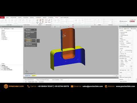
  3. Import into Your Software: Launch your preferred 3D CAD program (such as SolidWorks, Siemens NX, or Autodesk Inventor) and use the File > Open or Import option to open the newly renamed .x_t file.
  4. Use a Dedicated Viewer: If you do not have a full modeling suite installed, you can use free tools like eDrawings Viewer or Parasolid-compatible web viewers to inspect the geometry.

Final Thoughts

Dealing with unexpected file formats can slow down project timelines, but opening Parasolid files does not have to be confusing. By simply adjusting file extensions and updating security settings, you can seamlessly import and manage any 3D CAD model without hassle.

3D CAD
Continue Reading | ความคิดเห็น

Precision Dentistry: How 3D CAD is Revolutionizing Digital Crown Lengthening Surgery

For years, crown lengthening was a procedure that relied heavily on a surgeon’s manual measurements and visual estimation. While effective, the margin for error was always a consideration. Today, the landscape of restorative and aesthetic dentistry has been transformed by the integration of digital workflows. By utilizing advanced 3D CAD software, dental professionals can now plan surgeries with a level of precision that was previously unimaginable.

What is Digital Crown Lengthening?

Digital crown lengthening is a procedure used to remove excess gum tissue and, in some cases, bone, to expose more of a tooth's surface. Whether it is for a "gummy smile" correction or to prepare a tooth for a functional crown, the digital approach ensures that the biological width is respected and the aesthetic outcome is predictable.

The process begins with a high-resolution intraoral scan and a CBCT (Cone Beam Computed Tomography) scan. These data sets provide a comprehensive view of both the soft tissue and the underlying bone structure.

The Power of 3D CAD in Surgical Planning

The core of this technological leap lies in the planning phase. By leveraging 3D CAD (Computer-Aided Design) tools, clinicians can create a "digital twin" of the patient’s mouth. This allows the surgeon to virtually design the new gum line and determine exactly how much bone needs to be contoured.

Because the planning happens in a digital environment, the dentist can simulate the final result and make adjustments before the actual procedure begins. This eliminates guesswork and ensures that the final restoration—be it a veneer or a crown—will fit perfectly within the newly established dimensions.

From Digital Design to Surgical Reality

Once the design is finalized within the 3D CAD environment, the data is used to manufacture a custom surgical guide, typically via 3D printing. This guide fits securely over the patient’s teeth during surgery, acting as a physical map for the dentist.

The guide indicates exactly where to make incisions and where to contour the bone. The benefits for the patient are numerous: * Reduced Surgery Time: The procedure is faster because the "decisions" were made during the planning phase. * Faster Healing: More precise incisions lead to less trauma to the surrounding tissue. * Superior Aesthetics: The final gum line is symmetrical and exactly as planned.

Digital crown lengthening represents the perfect marriage of biology and technology, offering patients a safer, more accurate, and highly aesthetic surgical experience.

3D CAD
Continue Reading | ความคิดเห็น

Unlocking the Power of 3D CAD: Real-World Applications in Engineering and Simulation

Have you ever looked at a complex mechanical assembly or a stunning dynamic animation and wondered, "Where can this actually be used?" In today's fast-paced industrial landscape, computer-aided design has evolved far beyond basic 2D drafting. By leveraging advanced 3D CAD technology, engineers and product designers can conceptualize, test, and refine intricate designs long before physical manufacturing ever begins.

From Concept to Motion: Animation and Simulation

Modern engineering software like SolidWorks does much more than render static models. It empowers creators to run realistic simulations, test structural integrity, analyze stress points, and create smooth mechanism animations.

When you animate a functional design, you aren't just making a visually appealing video—you are validating motion and functionality. Stress testing a virtual prototype helps identify potential mechanical failures, optimize material usage, and drastically reduce physical prototyping costs. Integrating high-performance 3D CAD workflows ensures that every moving component interacts seamlessly, saving valuable time and capital during the product development lifecycle.

Where Can You Apply These Skills?

The ability to design, animate, and simulate dynamic systems opens doors across a wide variety of cutting-edge industries:

  • Automotive and Aerospace: Designing high-performance engine components, aerodynamic bodies, and landing gear mechanisms with sub-millimeter precision.
  • Robotics and Automation: Modeling robotic arms, automated assembly lines, and kinetic machinery to verify motion paths and prevent mechanical collisions.
  • Consumer Electronics: Crafting sleek, durable product enclosures that protect internal components while optimizing user ergonomics.
  • Medical Devices: Developing customized prosthetics, surgical tools, and life-saving equipment that require strict safety simulations and compliance.

Embrace the Future of Design

Whether you are an aspiring student, an independent designer, or an experienced engineer, mastering 3D CAD tools unlocks endless possibilities for innovation. As manufacturing standards shift toward virtual testing and digital twins, the ability to blend solid modeling with motion animation and simulation remains one of the most valuable skill sets in modern technology.

3D CAD
Continue Reading | ความคิดเห็น

Text to 3D CAD: How AI-Powered Multi-Agent Systems Are Changing Manufacturing

Thursday, August 20, 2026

Imagine describing a physical object in plain English and watching a complete, 3D printable file materialize in seconds. What once sounded like science fiction is now becoming a reality through cutting-edge artificial intelligence. Enter MAC (Multi-Agent CAD), an innovative system designed to bridge the gap between simple text prompts and functional manufacturing models.

What is Multi-Agent CAD (MAC)?

Traditional 3D CAD software often requires years of practice, precise mathematical inputs, and complex manual drafting. MAC changes this paradigm by using a collaborative network of specialized AI agents. Instead of relying on a single AI model to guess the exact geometry of an object, MAC splits the workload among multiple intelligent agents. Some agents analyze the text prompt, others generate the underlying parametric code, and additional agents inspect the design to ensure structural viability.

This multi-agent approach allows the system to generate clean, editable, and highly accurate parametric models rather than distorted 3D meshes. By translating descriptive text directly into code-based geometry, MAC creates physical parts that are optimized for production and ready for 3D printing.

Why Text-to-CAD Technology Matters

The integration of generative AI into 3D CAD workflows brings several major advantages to engineers, industrial designers, and hobbyists alike:

  • Rapid Prototyping: Turn creative concepts into physical objects without spending hours on initial sketching and baseline modeling.
  • Accessibility: Lower the barrier to entry, allowing non-experts to generate custom parts without navigating steep software learning curves.
  • Parametric Accuracy: Because MAC produces code-driven geometry rather than mere visual surfaces, the output remains fully customizable, precise, and structurally sound.

The Future of Digital Design

While human expertise remains essential for complex mechanical engineering, tools like MAC represent a massive leap forward for rapid design iteration. The future of 3D CAD is evolving into a hybrid process—one where humans provide creative intent and AI handles the tedious drafting tasks. Whether you are an experienced engineer or a desktop manufacturing enthusiast, text-driven CAD modeling is set to redefine how we bring digital ideas into the real world.

3D CAD
Continue Reading | ความคิดเห็น

Step-by-Step 3D CAD Tutorial: Designing a Mechanical Mounting Bracket in AutoCAD

Are you looking to level up your mechanical engineering skills or master computer-aided design? Transitioning from 2D drafting to solid modeling is one of the most rewarding steps in modern engineering. By leveraging power-packed 3D CAD software like AutoCAD, you can transform flat conceptual sketches into highly accurate, detailed mechanical components ready for manufacturing.

In this practical guide, we will explore the fundamental steps and techniques required to model a detailed mechanical mounting bracket from scratch.

Essential Tools for Mechanical Solid Modeling

Creating robust mechanical parts relies on mastering a few core solid modeling operations. When working on a mounting bracket or similar mechanical component, you will frequently utilize:

  • Extrude: Convert basic 2D closed polylines into 3D solid shapes by adding height or depth.
  • Subtract: Hollow out sections, create bolt holes, or carve keyways by subtracting one solid shape from another.
  • Union & Intersect: Combine multiple distinct solids into a single unified object or extract overlapping geometries.

Understanding how these boolean operations interact allows you to build sophisticated components out of simple geometric primitives.

Designing a Mechanical Mounting Bracket Step-by-Step

To build a realistic mechanical mounting bracket, precision is key. Follow these practical stages during your modeling workflow:

  1. Draft the Base Profile: Start in a 2D view by sketching the base plate and side support ribs with exact dimensions.
  2. Convert to 3D: Apply the Extrude tool to give thickness to your base and vertical mounting walls.
  3. Add Fastener Holes: Draw 2D circles at the designated mounting points, extrude them through the solid body, and apply the Subtract command to generate precise screw clearance holes.
  4. Refine and Fillet: Smooth sharp outer edges using the Fillet Edge command to reduce stress concentrations in your 3D CAD model.

Tips for an Efficient Modeling Workflow

Mastering 3D CAD modeling requires both technical knowledge and disciplined habits. Always ensure your 2D sketches are properly closed before extruding to avoid mesh or surface errors. Additionally, utilize custom User Coordinate Systems (UCS) when placing features on angled surfaces, and regularly switch visual styles (from Wireframe to Conceptual or X-Ray) to inspect your model's internal geometry.

With consistent practice on real-world projects like mounting brackets, you will quickly develop the speed and confidence needed for professional mechanical design.

3D CAD
Continue Reading | ความคิดเห็น

Essential 3D CAD Practice: How to Model a Mechanical Mounting Bracket

Designing mechanical components requires precision, efficiency, and a solid grasp of core modeling tools. Whether you are an aspiring mechanical engineer or a seasoned draftsman looking to sharpen your skills, practicing real-world component design is the best way to improve. In this guide, we explore how to create a detailed mechanical mounting bracket, offering an ideal exercise to strengthen your 3D CAD abilities.

Fundamental Tools for 3D Mechanical Modeling

Building complex mechanical parts in AutoCAD relies on mastering a few fundamental 3D commands. A mounting bracket, for instance, tests your ability to combine base shapes, create precise cutouts, and align geometries effectively.

Key operations featured in this practice exercise include: - Extrude: Transforming 2D cross-sections into 3D solid objects. - Subtract: Removing internal geometries to create mounting holes, counterbores, and slots. - Presspull: Dynamically modifying faces and extruding bounded areas for rapid design iteration. - Union: Combining multiple distinct solids into a unified, single component.

By understanding how these tools interact, you can approach even the most intricate mechanical blueprints with clarity and confidence.

Step-by-Step Approach to the Bracket Design

To begin modeling the bracket, start by establishing the primary 2D profile. Accuracy at this stage is critical, as any dimensional error in the base sketch will carry over to the final 3D model.

  1. Draft the Base Profile: Draw the foundational 2D outline of the bracket using accurate dimensions and centerlines.
  2. Convert to 3D Solids: Apply the EXTRUDE or PRESSPULL command to add depth to the base plate and upright support structures.
  3. Incorporate Feature Cutouts: Utilize boolean operations like SUBTRACT to carve out bolt mounting holes and center clearance slots.
  4. Refine and Inspect: Apply fillets or chamfers to sharp edges to optimize structural integrity, then switch visual styles to inspect your solid model from multiple angles.

Elevate Your Mechanical Design Skills

Mastering modern 3D CAD workflows isn't just about learning software commands; it is about developing a structured, logical approach to 3D spatial problem-solving. Completing practical hands-on exercises helps bridge the gap between theoretical knowledge and workplace execution.

Take time to work through this mechanical mounting bracket exercise, experiment with varied dimensions, and continue building your proficiency in 3D CAD modeling today!

3D CAD
Continue Reading | ความคิดเห็น

Level Up Your 3D CAD Skills: Speed Battles, Tutorials, and Expert Tips

Are you ready to test your speed, efficiency, and precision in digital design? Whether you are a seasoned engineer, a passionate designer, or a student looking to enhance your skill set, pushing your boundaries in 3D CAD can be both thrilling and immensely rewarding.

Speed modeling battles have rapidly become the ultimate arena for creators to showcase their expertise under pressure. However, behind every lightning-fast modeler is a solid foundation built on proven workflows, keyboard shortcuts, and clever techniques.

The Thrill of Competitive Speed Modeling

What separates an average designer from a lightning-fast pro? It usually comes down to tool mastery, feature organization, and strategic planning before drawing the very first sketch. In fast-paced modeling competitions, participants face off against the clock to recreate complex parts accurately in record time.

Watching or participating in these live battles offers a unique window into how experts solve complex geometric problems on the fly. You get to observe different design approaches, clever constraint applications, and minimal-step techniques that you can immediately integrate into your own workflow.

Essential Tips to Supercharge Your Design Workflow

Speed is not merely about clicking fast; it is about working smart. To significantly boost your efficiency in 3D CAD, consider implementing these practical strategies into your routine:

  • Master Keyboard Shortcuts: Customizing and memorizing hotkeys for your most frequently used commands saves precious seconds on every feature setup.
  • Plan Before You Sketch: Spend a few moments analyzing the overall geometry and base features of a model before starting. A logical feature tree simplifies future edits and avoids rebuild errors.
  • Leverage Constraints Wisely: Fully constraining your sketches early on prevents unexpected model breaks down the line, saving you substantial troubleshooting time.

Join the Community and Test Your Limits

Whether you want to compete against top designers in live speed challenges or simply polish your workflow through step-by-step tutorials, continuous practice is key. Mastering 3D CAD software is an ongoing journey of learning, adapting, and refining your technique. Stay curious, keep practicing, and don't hesitate to put your modeling skills to the ultimate test!

3D CAD
Continue Reading | ความคิดเห็น

How to Download and Install 3D CAD Software: Complete Setup Guide for Windows and Mac

Whether you are an engineer, architect, or digital artist, having a reliable 3D CAD software package installed on your computer is essential for bringing your creative visions to life. From initial product drafting to complex architectural modeling, modern design programs rely on smooth integration with your operating system to deliver optimal performance.

However, navigating the download and installation process across different operating systems like Windows and macOS can sometimes present unexpected challenges. In this comprehensive setup guide, we will walk you through the essential steps to get your design software up and running without hassle.

Step 1: Check System Requirements and Prepare Your Device

Before beginning any installation, ensure your computer meets the hardware specifications required by your design program. High-performance drafting tools depend heavily on processing power, RAM, and graphics acceleration.

  • Windows Users: Verify that your graphics card drivers are fully updated to prevent rendering glitches and performance lag during intensive tasks.
  • macOS Users: Ensure operating system compatibility, particularly if your device uses Apple Silicon (M1/M2/M3 chips), to confirm whether the installer runs natively or requires translation layers like Rosetta 2.
  • Disk Space: Clear out temporary files and ensure you have sufficient free SSD or HDD space for both the installer and workspace cache.

Step 2: Downloading and Running the Installer

To protect your system from security risks, always download your 3D CAD software directly from official, trusted sources or authorized distributors.

  1. Locate the downloaded file (.exe for Windows or .dmg/.pkg for macOS) in your system’s Downloads directory.
  2. Launch the installer and grant the necessary administrator privileges when prompted by your operating system.
  3. Follow the installation wizard, choosing your preferred installation path and selecting any essential add-ons or driver plugins required for your workflow.

Step 3: Licensing and Initial Performance Optimization

Once the setup process is complete, launch the application for the first time. You will typically be prompted to sign in with your user account, enter a valid license key, or activate an educational or trial license.

After activating your product, take a few minutes to navigate to the preferences menu. Adjust your default unit measurements, graphics performance settings, and autosave intervals to match your hardware capabilities. With your 3D CAD environment fully configured, you are ready to jump straight into your next modeling project!

3D CAD
Continue Reading | ความคิดเห็น

Master AutoCAD Polar Array: Create Precise Circular Patterns in 3D CAD

Wednesday, August 19, 2026

Designing symmetrical parts and mechanical components does not have to be a tedious, repetitive process. Whether you are drafting basic 2D gears, flange hole patterns, or intricate architectural features, mastering the AutoCAD Polar Array tool is an absolute game-changer. It allows designers to duplicate objects around a central axis instantly, saving valuable drafting time while ensuring mathematical precision.

What is the AutoCAD Polar Array Tool?

The Polar Array command automatically distributes copies of selected objects in a circular pattern around a specified center point. Instead of manually copying and rotating individual elements—a method prone to cumulative degree errors—the array tool calculates exact spacing and angles dynamically.

How to Create Perfect Circular Patterns Fast

Creating a polar array in AutoCAD is fast and intuitive. Follow these simple steps:

  1. Select the Object: Type ARRAYPOLAR in the command line (or choose the Polar Array icon from the Modify panel) and pick the geometry you want to repeat.
  2. Specify the Center Point: Click the precise central axis point around which your objects should rotate.
  3. Adjust the Settings: Use the contextual ribbon tab to set the total number of items, fill angle (such as 360 degrees for a full circle), and row count.
  4. Close the Array: Review the dynamic real-time preview and click Close Array to finalize your pattern.

Elevating Efficiency in Modern 3D CAD Workflows

While polar arrays are a staple of 2D drafting, they play a vital role when transitioning your concepts into robust 3D CAD modeling environments. Precision at the initial sketch stage directly impacts the success of subsequent 3D operations, such as extruding circular bolt patterns, lofting complex geometries, or building rotational assemblies.

By utilizing dynamic associative arrays, you can easily tweak object counts or radial dimensions at any point later in your design pipeline. Integrating these smart circular patterns into your daily 3D CAD workflow eliminates guesswork, drastically minimizes drawing errors, and accelerates your overall project delivery. Give the polar array command a try on your next project to instantly boost your drafting productivity!

3D CAD
Continue Reading | ความคิดเห็น

From Concept to Reality: How 3D CAD and 3D Printing Transform Product Development

In the fast-paced world of modern manufacturing, the journey from a spark of inspiration to a physical product has been radically shortened. This revolution is driven by two powerhouse technologies: advanced 3D printing and sophisticated 3D CAD software. Together, they allow designers and engineers to iterate faster, reduce costs, and bring functional prototypes to life with unprecedented precision.

The Foundation: Design with Precision

Every great product begins as a digital blueprint. Using 3D CAD (Computer-Aided Design), developers can create intricate geometries and mechanical assemblies that were once impossible to visualize. This digital stage is crucial because it allows for virtual testing and stress analysis before a single cent is spent on materials. By perfecting the design in a digital environment, businesses ensure that the final physical prototype will function exactly as intended.


Choosing the Right Tool for the Job

Once the digital model is ready, the next step is selecting the appropriate 3D printing technology. Not all printers are created equal, and the choice often depends on the specific requirements of the product development stage:

  • FDM (Fused Deposition Modeling): Ideal for early-stage conceptual models and basic functional testing due to its cost-effectiveness and wide range of thermoplastic materials.
  • SLA (Stereolithography): Perfect for parts requiring high detail and a smooth surface finish, such as jewelry or intricate consumer electronics housings.
  • SLS (Selective Laser Sintering): The go-to for industrial-grade, durable prototypes and end-use parts that need to withstand significant mechanical stress.

Accelerating the Iteration Cycle

The true magic of integrating 3D CAD with 3D printing lies in the speed of the feedback loop. In traditional manufacturing, creating a mold or a tool could take weeks. Today, a designer can identify a flaw in a physical prototype, adjust the digital file, and start printing a revised version in a matter of hours. This "fail fast" approach allows teams to refine ergonomics, aesthetics, and mechanical fit in record time.

Conclusion

3D printing is no longer just a hobbyist’s tool; it is a cornerstone of professional product development. By mastering the synergy between digital design and physical production, innovators can navigate the complex path from a simple idea to a market-ready product with confidence and efficiency. Whether you are an entrepreneur or a seasoned engineer, leveraging these technologies is the key to staying competitive in today's industrial landscape.

3D CAD
Continue Reading | ความคิดเห็น

How to Master Linear and Circular Patterns in Siemens NX 3D CAD

When working on complex engineering designs, manually replicating individual features can consume hours of unnecessary effort. Whether you are a student or an industry professional, mastering efficiency tools in modern 3D CAD software is essential for streamlining your modeling workflow. Among these tools, the Pattern Feature in Siemens NX (UG NX) stands out as one of the most powerful capabilities for duplicating geometric elements quickly and accurately.

In this beginner-friendly guide, we will explore how to effectively utilize Linear and Circular Patterns in Siemens NX to elevate your design process.

What is the Pattern Feature in Siemens NX?

The Pattern Feature allows designers to create multiple instances of selected features—such as holes, bosses, or slots—and arrange them in specific geometric layouts. Instead of drawing each element individually, you can define a single master feature and specify the direction, spacing, and quantity for automatic generation. This approach not only saves significant modeling time but also ensures parametric consistency across your entire design.

Mastering Linear Patterns

A Linear Pattern replicates selected features along one or two linear directions. This technique is ideal for creating arrayed components like mounting holes, heat sink fins, or structural ribs.

To create a linear pattern in Siemens NX: 1. Select the feature you wish to multiply. 2. Define the primary direction vector (such as an edge, axis, or datum line). 3. Choose your layout method (e.g., Count and Pitch, Count and Span, or Pitch and Span) and enter the values. 4. Add a secondary direction if you need to create a two-dimensional grid layout.

Mastering Circular Patterns

When designing rotational or symmetrical components—such as wheel rims, gears, flange bolt patterns, or turbine blades—the Circular Pattern option is your best choice. It distributes features evenly around a specified axis of rotation.

To execute a circular pattern: 1. Choose the target feature for replication. 2. Define the center axis of rotation and the base point. 3. Input the total number of instances and the total angular span (e.g., 360 degrees for a full circular array).

Why Pattern Features Matter in 3D CAD

Leveraging automation tools like linear and circular patterns is crucial for anyone looking to excel in 3D CAD design. Utilizing built-in pattern capabilities in your 3D CAD environment drastically reduces manual rework, minimizes design errors, and simplifies future modifications. By mastering these foundational pattern techniques in Siemens NX, you can boost your productivity and build clean, fully parametric models with confidence.

3D CAD
Continue Reading | ความคิดเห็น

Master Ultra-Realistic 3D CAD Animation: Combining SolidWorks and Blender

In today's fast-paced digital landscape, visual representation is everything. Whether you are an engineer showcasing a groundbreaking product design or a digital artist bringing complex mechanical movements to life, achieving high-fidelity visuals is essential. By bridging the gap between precise engineering tools and high-end artistic rendering, creators can transform standard 3D CAD models into photorealistic, cinematic animations.

The Power of SolidWorks Meets the Artistry of Blender

SolidWorks has long been an industry standard for mechanical design and parametric modeling. It provides unmatched precision, allowing designers to build intricate components with exact real-world dimensions and constraints. However, while traditional engineering tools excel at functional accuracy, generating cinematic lighting, lifelike textures, and dynamic camera movement often requires advanced rendering software.

This is where Blender enters the workflow. As a versatile, open-source 3D creation suite, Blender offers industry-leading rendering engines, realistic material shaders, and flexible animation tools. Integrating your 3D CAD designs into Blender opens up endless possibilities for creating studio-quality visuals, complete with accurate depth-of-field, lens flares, and physically based rendering (PBR) materials.

Key Workflow Steps for Ultra-Realism

To turn rigid mechanical assemblies into stunning animations, professional creators rely on a seamless hybrid workflow:

  1. Precision CAD Modeling: Build your assembly in SolidWorks or your preferred 3D CAD software, ensuring every joint, bolt, and moving part is structured logically.
  2. Mesh Optimization: Export your model into optimized formats like OBJ or FBX. Pay close attention to mesh density to balance detailed geometric curves with smooth rendering performance.
  3. Advanced Shading and Texturing: Import the model into Blender to assign realistic surface properties, such as brushed metals, clear glass, or subtle surface imperfections like scratches and fingerprints.
  4. Cinematic Lighting and Motion: Utilize studio lighting setups or HDRI environments alongside smooth camera movement to emphasize the sleek contours and functional design of your mechanism.

Elevate Your Visuals Today

Combining the structural accuracy of CAD software with the visual freedom of modern rendering tools is the ultimate secret to producing ultra-realistic animations. By adopting this powerful workflow, you can create compelling product visualizations, engaging marketing materials, and impressive portfolio pieces that captivate any audience.

3D CAD
Continue Reading | ความคิดเห็น

Mastering 3D CAD: The Ultimate Guide to the AutoCAD 3D Modeling Marathon

In the rapidly evolving world of architectural and mechanical design, transitioning from flat sketches to spatial depth is no longer just an advantage—it is a necessity. Our latest installment, the "AutoCAD 3D Modeling Marathon Part 3," is designed to bridge the gap between basic sketching and professional-grade visualization. Whether you are a student or a seasoned professional, mastering 3D CAD workflows is the key to unlocking your full creative potential.

Why AutoCAD for 3D Modeling?

While many know AutoCAD as the industry standard for 2D drafting, its 3D capabilities are equally robust. Utilizing 3D CAD software allows designers to visualize spatial relationships, detect structural interference, and produce realistic renderings that help clients understand the final product before a single brick is laid or a part is manufactured. This tutorial series focuses on making these complex tools accessible and easy to implement in your daily workflow.

What You’ll Learn in Part 3

In this third part of our marathon series, we move beyond simple shapes and dive into more intricate modeling techniques. This session covers the transition from basic wireframes to solid modeling, focusing on:

  • Advanced Extrusions and Revolves: Creating complex volumes from simple 2D profiles.
  • Boolean Operations: Learning how to subtract, union, and intersect objects to form unique geometries.
  • Precision Editing: Using Gizmos and sub-object selection to refine your models with surgical accuracy.

The goal of this marathon is to build your "muscle memory." By following along with real-world examples, you will find that the commands become second nature, allowing you to focus on the design rather than the software interface.

Elevate Your Career with 3D CAD

The demand for high-quality visualization is at an all-time high. By mastering 3D CAD techniques, you position yourself as a versatile asset in fields ranging from interior design to aerospace engineering. The ability to iterate quickly and present ideas in three dimensions significantly reduces project timelines and minimizes errors.

If you are ready to take your technical drawing skills to the next level, join us in this comprehensive tutorial. Practice is the only path to mastery, and there is no better place to start than with our step-by-step marathon guide. Grab your mouse, open your software, and let’s start building!

3D CAD
Continue Reading | ความคิดเห็น

Master 3D CAD Modeling: AutoCAD Complete Tutorial Series Part 3

Tuesday, August 18, 2026

Are you ready to take your digital design skills to the next level? Welcome to Part 3 of our complete AutoCAD tutorial series, where we continue our deep dive into the world of spatial design. Whether you are an aspiring mechanical engineer, an architect, or a product designer, mastering modern 3D CAD software is an essential step toward turning your creative concepts into precise, real-world models.

Deepening Your 3D Modeling Expertise

In this third installment of our modeling marathon, we transition from basic geometric shapes into more complex solid modeling techniques. Understanding how to navigate a 3-dimensional workspace requires a solid grasp of User Coordinate Systems (UCS), dynamic viewports, and visual styles. This tutorial breaks down these fundamental concepts into manageable, easy-to-follow steps so you can design with clarity and confidence.

Core Tools and Techniques Covered

To build complex structures efficiently, you need to master AutoCAD's core 3D toolset. In this lesson, you will explore key features including:

  • Extrude and Presspull: Learn how to instantly transform flat 2D sketches into robust 3D solids.
  • Revolve and Sweep: Discover how to generate intricate rotational designs and path-based geometries effortlessly.
  • Boolean Operations: Combine, subtract, and intersect primary shapes to create sophisticated components with maximum accuracy.

By practicing these essential operations, you will significantly enhance your 3D CAD workflow and reduce drafting errors in complex engineering projects.

Streamlining Your Workflow from 2D to 3D

One of the biggest challenges designers face is shifting their technical mindset from traditional 2D drafting to a multi-dimensional spatial environment. Part 3 focuses heavily on practical exercises designed to bridge this exact gap. You will learn essential keyboard shortcuts, strategic layer management, and practical visualization tips that dramatically speed up your production time without sacrificing detail.

Step Up Your Design Skills Today

Mastering complex software takes practice, but following structured, hands-on tutorials accelerates your learning curve. Implementing these step-by-step methods will give you the confidence to tackle real-world drafting challenges in any professional 3D CAD environment. Watch the complete video guide, follow along with the exercises, and continue building your expertise today!

3D CAD
Continue Reading | ความคิดเห็น

Mastering Mechanical Design: Step-by-Step 3D CAD Assembly & Technical Drawing Guide

Mechanical engineering relies heavily on turning complex concepts into tangible, functional components. Whether you are an aspiring engineer, student, or seasoned designer, mastering the full workflow in modern 3D CAD software is essential for bringing your ideas to life with speed and precision.

In this comprehensive breakdown, we explore an end-to-end mechanical design process—from part inspection to complex mechanical assembly and detailed technical drawing generation.

Navigating the Mechanical Assembly Workflow

Building a multi-part mechanical system requires more than just creating individual 3D geometries; it demands a clear understanding of how components interact. During the assembly phase, designers must apply correct mate conditions, mechanical constraints, and alignment checks to ensure smooth kinematic performance.

By utilizing advanced 3D CAD tools, engineers can inspect internal clearances, analyze dynamic motion, and detect component interference long before a physical prototype is manufactured. This digital prototyping phase significantly minimizes material waste and speeds up development cycles.

Translating 3D Models into Precise Technical Drawings

Once your 3D mechanical assembly is finalized, the next crucial step is generating shop-ready manufacturing documentation. A functional digital model relies on standardized 2D blueprints so machinists and technicians can produce parts accurately.

Key aspects of the drawing breakdown include: - Orthographic & Section Views: Generating top, front, and cross-sectional views to reveal internal geometry. - Exploded Views & BOMs: Creating detailed Bill of Materials (BOM) tables and exploded assembly views for seamless assembly lines. - Dimensioning & Tolerancing: Applying essential geometric dimensions and tolerances (GD&T) to guarantee perfect fit and function.

Elevate Your Engineering Workflow

Adopting an integrated, parametric workflow ensures that your design intent remains intact throughout the project lifecycle. When a single parameter changes in a part model, your high-level assembly and 2D blueprints automatically update. Developing proficiency in 3D CAD empowers you to deliver professional, industry-standard engineering deliverables efficiently.

3D CAD
Continue Reading | ความคิดเห็น

Mastering Mechanical Assembly: A Step-by-Step 3D CAD Workflow Guide

Modern engineering relies heavily on digital precision, and mastering a full mechanical design workflow is essential for creating reliable, production-ready parts. Whether you are an aspiring engineer, a product designer, or a seasoned draftsperson, understanding how to transition from individual components to a complete mechanical assembly is a game-changer. In this breakdown, we walk you through the essential steps of building mechanical assemblies and generating detailed technical drawings using 3D CAD software.

1. Building and Inspecting Mechanical Assemblies

The design process begins by bringing individual parts into a single digital environment. Instead of viewing components in isolation, creating a complete assembly allows you to inspect how mating surfaces interact, verify clearances, and eliminate physical interference before manufacturing ever begins.

Utilizing powerful 3D CAD tools, designers can apply parametric constraints—such as concentricity, coincidence, and distance mates—to simulate real-world mechanical motion. Inspecting the model at this stage ensures that moving parts function smoothly and that every fastener, gear, and housing fits perfectly within the specified tolerances.

2. Translating 3D Models into Precise Technical Drawings

Once the digital assembly is finalized, the next vital step is converting the complex model into standardized 2D technical drawings. While the three-dimensional representation provides visual clarity, shop floor technicians rely on 2D drawings for exact dimensions, geometric tolerances, material specifications, and step-by-step assembly instructions.

A comprehensive technical drawing breakdown includes: * Exploded Views: Clearly displaying how each individual component fits into the overall assembly. * Bill of Materials (BOM): An itemized list detailing part numbers, quantities, and materials needed for production. * Section and Detail Views: Revealing internal geometry and intricate features that are hidden in standard orthogonal views.

3. Elevating Your Design Efficiency

Adopting a structured workflow in 3D CAD drastically reduces design iteration time and prevents costly errors during production. By mastering both assembly inspection and technical drafting, you bridge the gap between abstract conceptualization and real-world manufacturing. Start applying these step-by-step techniques today to streamline your engineering projects and produce professional-grade designs.

3D CAD
Continue Reading | ความคิดเห็น

Labels

.skp download 12-32V 12x10 m structure 17th Century 190E 2.5-16 1950s Roadster 1954 1969 Chevrolet Camaro 1970 Cougar 1986 F250 1991 1992 Bugatti 1993 2009 2015Softwares: STEP / IGES 2017 2020 Honda Odyssey J 2021 Buick 2022 2022 Nissan Maxima 2K textures 2T racer 300 SL 3D 3d aircraft model 3D Airplane 3D animation 3D Animation 3D animation model 3d architecture 3D artists 3D Asset 3D asset download 3D assets 3d assets pack 3D battery holder download 3D Boat 3D Building 3d building model 3D Cad 3D CAD 3D CAD Download 3D CAD Model 3D CAD Models 3D car 3D car download 3D car model 3D Character 3d church 3D church model 3D crossbow bolt 3D Design 3D Design Resource 3D design resources 3D download 3D downloads 3D drone 3D electronics model 3d environment 3D equipment download 3d file library 3D files for animation 3D Furniture 3D game assets 3D gaming headset 3D geometry 3D guns 3D Headphone Render 3D illustration 3d interface 3D Jewelry 3D jewelry model 3D lamp 3D Model 3D model AA battery holder 3D model download 3D model for games 3D Model Free 3D model library 3D Modeling 3d modeling resources 3d models 3D models for Blender 3D monitor model 3D PC Tower 3D phone 3D phone model 3D Printable 3D printable model 3D Printer 3D Printing 3D product demo 3D product design 3D project 3D Props 3D render 3d rendering 3D Rendering Asset 3D rendering assets 3D resources 3D robot 3d scan 3d scene 3d space scene 3D structure 3d temple 3D textures 3D truck model 3D vehicle 3D visualization 3D Warehouse 3D Warehouse car model 3D Warehouse download 3D weapon 3D weapon model 3d weapon pack 3D Weapons 3D-model 3D-visualization 3DDownload 3DModel 3ds Max 3ds Max 3D 3ds Max 3D assets 3ds Max 3D models 3ds Max model 4-cylinder engine 4K textures 5-DOF 5-Hole 50cc motorcycle 50W LED 6-axis robot 6x6 truck model 7.62x39mm Abandoned ABB Robot Abstract Interface abstract sci fi Acura NSX Additive Manufacturing Adventure Assets Aero Chainring Aerospace design agricultural model airbus a340 600 Airbus A340-600 Aircraft Aircraft 3D Aircraft Design aircraft model Aircraft Support Vehicle Airplane Airport airport rescue AK-12 AK-47 AK-74 AK47 Alfa Romeo Alfa Romeo 4C Alien Alien Spacecraft All-Terrain Vehicle Altair aluminium railing ambulance ambulance typeiambulance emergencyvehicle ems medicaltr AMC Matador AMC Rebel AMG AMG 6x6 AMG GTR AMG SL 63 Ammo Box Ammunition ammunition 3D ancient architecture ancient building ancient building 3d ancient pyramid ancient rome ancient ruins Ancient Stairs Ancient Sword Ancient Temple Ancient Tower Ancient Weapon Android animal Animation animation asset animation assets animation model animation prop Anime Antique Antique Cannon Antique Table Appliance Application Mat Aquadelmo Boat AR AR-15 AR19A2 Arabica Cafe arcade racing Archaeology ArchiCAD architectural 3d Architectural 3D Asset architectural 3d model Architectural Asset Architectural Assets architectural components architectural design architectural model architectural visualization Architecture architecture 3D architecture 3d model architecture asset architecture assets architecture design Architecture Model architecture visualization ArchViz ArchViz Assets ArchWave Chair Arduino UNO ARFF Scania Armchair armenia heritage Armored Car Army Crate Artificial Intelligence Artillery Artisan Pendant Artist Tools Asia temple Asian Architecture Assassin's Creed assault rifle Assault Rifle 3D Assembly assembly files Assembly Line Asset Assets Aston Martin ATV 3D ATV Quad AUBO-i3 Audi Audi A7 Audi R8 Audi R8 V10 audio 3D model audio interface Autocad AutoCAD AutoCAD Plant 3D AutoCAD Tips AutoCAD Training AutoCAD Tutorial Autodesk Autodesk Inventor automation Automation components automobile Automotive Automotive 3D automotive 3D asset automotive 3D assets automotive 3D design automotive 3D download Automotive 3D Model automotive design Automotive Engineering automotive interior automotive model automotive modeling automotive visualization Aventador Aviation aviation 3D aviation 3d asset Aviation Model Axe Axe 3D Axe Pendant Axel Weapon B-2 Spirit Balcony Railing Model Ball Bearing balustrade Baphomet Bar Counter Bar Stool Barstool Basic Beginners Bathroom Interior Battle Cruiser BCD 110 mm Bed Bedroom Decor Bedside Table Bell UH-1Y belt link Bench 3D Benelli M3 Bentley Bentley 4.5 Liter Berserk Bicycle 3D Bicycle Parts Bike Model BIM Modeling Black Wood Bleach Anime Bleachers Blender Blender 3D Blender 3D model Blender 3D models Blender Assets blender model Blender models blog image BMW 2015 BMW 3D Model BMW i8 BMW i8 3D model BMW M3 BMW R1200GS BMW X2 BMW X2 2020 Board Games boat Boat 3D Model Boeing 737 Bonaldo Arragan Book Shelf Bookcase Bookshelf Bookstore BORGEBY Bot Brabus G63 Brachacki Buffet Table Bufftech Rothbury Bugatti Chiron Bugatti EB110SS Buick Enclave Building Building 3D building 3d model Building Model Bullet 3D bullet pack Bullet Train Bunker Bus 3D C11 C4D C4D Assets C4D Scene Cabinet Door Model Cable drag chain Cable management cable stair CAD CAD assembly CAD Assembly CAD asset CAD Design CAD download CAD Drawing cad file CAD Files CAD library CAD model cad model download CAD Modeling CAD reference CAD resource CAD resources CAD Skills CAD Software CAD Tips CAD Troubleshooting CAD tutorial CAD Tutorial CAD Tutorials Cafe Interior Camaro 1977 Camaro Z28 3D model Camera Camper Camper Truck Camping 3D Camping car Cannon Cannon 3D cantilever stair Capital Ship Capsule Living car car 3D car 3D download Car 3D Model Car Carrier car concept car design car game model car interior car model car model 3D Car Modeling car rendering car suspension car tuning car visualization Car Wheel car-model carbine 3d Career Growth Cargo Container Cargo Ship Cargo truck Carrera GT Cars-Vehicles Cartoon Style Cartoon Tank Casa Magna Case Casino Assets Castle Church catapult design Cathedral CATIA CD player Central Asian architecture CG Artist CG Asset CG Assets CG Content CG Download CG Resource CGI cgi asset CGI assets CGI Car CGI model chain links chainsaw chair Chair Set Chakram Changhe Z-10 chapel 3d model Character Character Design Charizard chassis 3D chemical equipment Chesterfield Sofa Chevrolet Opala Chevrolet S-10 Chevrolet S10 Chevy Orange CheyTac M200 Chicago style stair china symbol kit chinese symbol 3d chipper machine Chopped Bug Chrysler Saratoga Church 3D church 3d model church asset ciFi 3D Cinema 4D cityrail CIVIC Class C RV Classic Architecture Classic Bike 3D Classic Car classic car 3d classic car 3D model classic car model classic greek temple 3d Classic Race Car Classic Sofa classic temple Classic Vehicle classical architecture Classical Building classical temple CNC CNC Machining CNC wood project CNC3D Cobot Coffee Table Coffee Table 3D Collaborative Robot Colored model Colt M16 Colt Revolver Command and Conquer Compass Components Computer Computer 3D Model Concept Art concept car concept design Console Construction Construction Asset Construction Machinery Construction Mech Construction Pack Construction Vehicle Construction Worker container house containers3D control box Control Cabinet Control Panel Control Panel 3D Controller Convertible Convertible car conveyor Conveyor 123 Conveyor Belt conveyor parts Conveyor System Cop car Copal railing Cordless Drill Corvette 3D model Corvette C8 Couch Counter Coupe CPU CPU chip Crawler Excavator Creative Tools Creature Creatures Crossbow crossbow model Crossover Pendant Crossover SUV Crown Lengthening cryosleep chamber Cryptodor crystal gem CS2 Cube cultural 3d model cultural architecture Curved Conveyor curved stair custom car Cyberpunk Cyborg Cycling Design cylinder 3d D Model DAF 6x6 Dana Darksaber david star pendant De Tomaso Pantera Deck Railing 3D decor art decorative vase Defender 110 demolition racing Design design inspiration Design Resources Design Software Desktop Organizer Details Uploaded:February 1st diamond diamond 3D diamond bracelet diamond model Diamond Pendant diamond ring diamonds Diesel engine Diesel truck digital art Digital Asset Digital Dentistry digital design Digital Manufacturing digital rendering Dining Set Dining Table Dispenser DIY DIY Design DIY machine DIY model DJI Inspire 1 Dodge Challenger Dodge Charger Dodge D300 Dodge Viper Dome Architecture Door 3D Download download 3D download 3d files download 3D model Download 3D Models Download file Download Free Downloadable downloadable 3D asset downloadable 3D assets DPF Dragon Axe Dragon Dagger Dragon Glaive Dragon Slayer Drive Racks Droid Drone Drone 3D Drone CAD Drone Scan DTM dually truck Dump Truck Dynamite EC11EBB24C03-1 educational 3D Eevee egyptian temple El Camaro electric car electric drill Electric Fireplace electric generator Electric Locomotive electric motor electric vehicle Electrical Box Electrical Control Panel Electrical Enclosure electrical outlet 3D electrical socket Electricity Electromagnet Electronics Electronics Design Electronics parts Emergency Switch emergency vehicle Enclosure Enclosure Design Energy Capsule Engine engine assembly engine CAD Engine Design engineering Engineering Engineering 3D Engineering 3D Asset engineering assets engineering Cad Engineering Design engineering design files Engineering Model Engineering Parts Engineering project Engineering Projects Engineering Reference Engineering Resource Engineering Software engineering tutorial engraving machine environment design Equipment Equipment Case ES64U2 Taurus Eternity Ring Eurocopter EC135 EV EV 3D model EV car 3D EVO X EVO8 Evolution 10 Evolution 2 Excavator Expedition Pack Expedition truck Explosives Exterior exterior design exterior modeling Exterior Prop F-16 Facility Factory Automation Factory Design Factory Layout FAMAS Fan Art Fans Fantasy Fantasy Asset Fantasy Assets Fantasy Knife Fantasy Sword Fantasy Tower Fantasy Weapon FBX fbx 3d model FEA fencing 3D fencing model Fiat 131 Mirafiori Wagon Fiat 6614 Fighter Aircraft Fighter Jet Fighter Plane Figure File Conversion Fire Axe fire truck 3D Firearm firearm 3D firearm model Fireplace 3D Fitness Equipment Flamethrower Flare Gun Fleetwood Icon floatplane Florence Duomo Flying Bot FN P90 fn scar FN SCAR-L Fomalhaut Leone Major EX Ford 3D Model Ford drag racer Ford F250 Ford Fiesta 2009 FORD FOCUS RS Ford Mustang forgotten temple Formula 1 Franchi SPAS-12 Free Free 3D Free 3D Asset free 3D assets free 3D car free 3D car download free 3D download Free 3D file Free 3D Files Free 3D Model Free 3D Model: Modern Minimalist Chair for Interior Visualization Free 3D Models free 3D models for games free 3D pack free 3d props free 3D SUV model free 3D vehicle free 3d warehouse free architectural model free architecture model Free CAD free cad 3D down loads Free CAD Download free CAD file Free cad file 3D Free CAD Files Free Car Model Free Download Free Downloads Free Model free SketchUp free SketchUp download Free SketchUp Files free SketchUp model free sketchup resource free-download Free3D Free3dmodel FreeCAD Freemodel Frigate Fuel Can Furniture Furniture 3D Furniture 3D Model Furniture Design Fuse Fusion 360 Futuristic futuristic 3d futuristic 3d model futuristic 3D models futuristic asset Futuristic Design futuristic props futuristic ui futuristic weapon G Class G Wagon Gadget Galactic Galil ARM Gallardo Spyder galvanized steel fence Game Asset game asset 3d game assets game design Game Dev game development game environment game environment model Game Ready game ready asset game ready model Game-Ready game-ready 3D game-ready model Game-Ready Models GameAsset gaming Gaming Assets Gaming Chair ganesh 3d garden pavilion Gate Valve GAZ-14 Chaika Gazebo 3D Gear Gearbox Gears General 3D Generative AI German Pistol Germany Ghost in the Shell Glass Table globe Glowing Weapon GMC Hummer EV GMC Suburban gold pendant Golden Pendant golden ring GrabCAD GrabCAD 3D Grabcad model Grade 80 grain silo Greek architecture Grenade Grenade 3D grenade launcher Grotti Carbonizzare grotti cheetah Group C GT R 2017 GT3 racing car GT500 GTA V gta v car 3d Gun 3D gun 3d model gun model gun models GunModel Guts Sword Gym Assets Halberd Hammer hanging lamp Hard Surface hard surface modeling HAT hatchback model Healthcare Heart Shape Ring Heat Exchange Heavy Equipment Heavy Machinery Helicopter helicopter 3D Helicopter 3D Model Hellcat Hellcat 3D Helmet Hexagon Table hibernation module Hidden Blade High Detail High Poly High Quality high quality 3D high-poly high-quality 3D high-quality 3D battery holder high-resolution historic building Historical historical 3D historical 3D model historical architecture Historical Building Historical Jewelry Historical Rifle Historical Structure Historical Weapon history building hmmwv 3d model Hobbies Hobby Hoist Home Decor Home Decor 3D Home Office Homologation HONDA Honda 3D model Honda CB 750 HONDA CIVIC Honda F1 Honda NSX Honda Odyssey Honda Prelude honda vfr 800 Hopper Feeder Hospital Hospital Bed 3D HSE Human model 3D Hummer 3D Model Hummer H6 hummer m998 Hunter Knife Hybrid car hydraulic Hydraulic Jack Hydraulic lift Hydraulic Ram Hydraulic Winch hydro turbine hyundai genesis coupe Hyundai IONIQ 5 N Ichigo Sword IGES IGS IKEA IL-2 Ilyushin IN-CAD 3D Indian Chief 1942 Indonesian Bus inductry Industrial Industrial 3D industrial 3D asset industrial 3D model Industrial Asset Industrial Automation Industrial Component Industrial design Industrial Design Industrial design 3D Industrial Equipment industrial generator industrial lighting Industrial Machine Model Industrial Machinery industrial model Industrial Pipes Industrial Prop Industrial Pump Industrial Robot industrial robot arm Industrial Safety Industrial Style Industrial Tool Industrial Vehicle Industry Inline Engine insect 3D Installation Guide Interface interior 3D interior 3d asset Interior Asset Interior Assets Interior Design interior design 3d interior design asset Interior Design Assets interior design model interior lighting Interior Props inventor IoT IRB 120 Irizar i6 Iron Man Islamic architecture Isometric Room ISUZU GIGA IWI Tavor TS12 jack Japanese Sword Japanese temple Japanese Weapons JDM Car jeep renegade 3d Jetbus jewelry Jewelry 3D jewelry 3d model Jewelry Design Jewelry Model Kaaba 3D model Kalashnikov Kalashnikov AK-12 Kamacho Karambit Katana Katana 3D Kawasaki Ki-61 Kennedy Town keyboard and mouse keyshot Kia Soul 2022 Kia Soul EX Kia XCeed Kids Slide Kiko Stool Kingdom Hearts Kitchen Assets Kitchen Scene Knife 3D Knight Sword Koenigsegg CCX KRISS Vector KTM 1190 RC8 Lada Ladder 3D Lamborghini Lamborghini Gallardo Lancer Evolution Land Rover Land Rover 2016 Land Rover Series 3 landscape 3D landscape design landscaping model laptop laser cut project laser cutting laser cutting design laser engraver Le Mans learning leather furniture Leather Sofa LED spotlight Lee-Enfield Lesson Lexus LX600 Liberty Walk Lift lifted truck lighting design lighting model Lightsaber limit switch linear actuator link chain link connector Living Room Living Room Furniture LODs Logistics Logistics design Lounge Chair Low Poly low poly car Low Poly Drone low polygon low-poly low-poly 3D models low-poly car low-poly crossbow Lowpoly lowpoly model LP560-4 Luftrettung Luxury Car luxury design M13 7.62mm belt link M1A1 Abrams M2 Browning M300 M4 Rifle M40A5 M4A1 M60 M60 Machine Gun macbook Machanic Parts Machete 3D Machine Machine design Machine Gun Machinery macintosh Magical Sword Magnum 44 Major Makarov PM Maker Mallory Tufted Malm Bed Mammoth Tank MAN 6x6 Manta Birostris 3D model manual punching machine manufacturable design Manufacturing Marine 3D marine 3D asset Maritime MARK 6 Martial Arts Marvel Maserati Master Link Material Handling Mauser 98k MAV Class 470 Maya Maya 3D Maya 3D files Maya 3D model Mayan Temple Mazda CX-5 Mazda MX-5 Mazda RX-8 MBSALG 601620 McKinley McLaren McLaren Senna Mech Mecha mechanic tools Mechanical mechanical 3D mechanical assembly Mechanical Asset mechanical connector mechanical design Mechanical Design mechanical engineering Mechanical Engineering Mechanical Model Mechanical Parts Mechanical Parts 3D Mechanical Reference mechanical robotic arm mechanical tool Mechanism Mechatronics Medical Drone Medical Equipment 3D Medieval Medieval Furniture Medieval Weapon Melee Weapon Melee Weapons Men in Black 3D Mercedes Mercedes Benz Mercedes-AMG GT R Mercedes-Benz Mercedes-Benz 190E Evo II Mercedes-Benz AMG SL 63 Mercedes-Benz Blue Wonder Mercedes-Benz C11 Metal Construction Metal Lava Metal Spindle Railing metal table Metallic Crate metering dispenser tank 3D MG 15 MG12H Mi-8 mid engine car Mil Mi-8 Military military 3D military 3d model Military Aircraft military asset Military Assets Military Helicopter military model Military Props military vehicle military vehicle 3d Milling Machine Milwaukee EP-2 Minarat Mosque MINI CNC Mini Cooper Mini Drone Mini Temple mini temple house Minigun Minimalist Design minimalist fence minimalist sofa Mining Mining Equipment Mining Tool minivan 3D Miscellaneous militarytanker watertransport cadmodel grabcad educatio Missile Mitsubishi Lancer Mitsubishi Lancer Evolution Mitsubishi Lancer Evolution X MK 45 Mk-I Motorcycle ml63 amg MOBA Tower Mobile Phone Model Modeling Modern Bedside Table Modern Bookcase Modern Chair Modern Decor Modern Design Modern Furniture Modern House modern lamp modern sofa Modern Style Modern Table Modern Teapoy Modern Weapons Modular Design Modular House Moisture Meter Monocular Monopteros temple Morning Star Morph Tool Mosin-Nagant mosque Mosque 3D motor motorbike 3D motorcycle Motorcycle 3D motorcycle 3D assets Motorcycle Design Motorcycle Helmet motorsport Movie Device 3D MP5 MUGEN R Muscle Car muscle car 3d music studio Musket MV Agusta F4 N7 Assault Rifle Naga Weapon Nash Healey Roadster Nash-Healey nature model Naval Cannon NEMA 17 Neuralyzer 3D Model Nightstand Nissan 180SX Nissan 350Z Nissan GTR Nissan Laurel C33 Nissan Maxima Nissan Skyline No Support NoAI Noom Noom Freyja Norton Commando Norton Domiracer Norton JPN Replica Notebook NSX 1992 NSX Type S Nuclear Nunchaku NX Unigraphics OBJ odzun monastery Off Road off-road vehicle Office Assets Office Chair Office Furniture old building Old Bus Old House Opala SS Opel Speedster OpenSCAD Oral Surgery orient temple oscar h set outdoor Bluetooth speaker outdoor furniture outdoor scene asset outdoor structure 3D Painel de Comando Elétrico Paint Roller PAJERO Pandem kit Panel Parametric Parasolid Part Design Particulate Filter Pattern Feature PBR PBR (ถ้ามี Texture) pbr 3d assets PBR Model PBR Ready pbr texture PBR textures PC Fan PCB endstop PDW Pelton turbine Pelton wheel Pendant 3D pendant lamp Pendant Model Personal Use License Peterbilt Peterbilt Truck PEUGEOT 3008 Peugeot 405 GLX Phaser phone 3D asset phone 3D model Phone Case Photogrammetry Photorealistic Pickaxe Pickup truck pickup truck 3D pickup truck model picnic table pipe piping Piping Tags: pipework Pirate Ship Pistol Pistol 3D Pixar Style Planetary Gear Plant Design Plant platform Plastic Barrel Plastic Bin Playground 3D Plywood Pallet PM pistol model Pneumatic System Pokémon Polar Array polestar Police 3D Model Police Box Police Car Police car 3D Police Radar Police Vehicle Porsche Porsche 918 Spyder Portable Drill Portal Power Power Tools PPSh-41 Prehistoric Prince of Persia Printable Model printable parts Printer Printstream product design Product Design Product Design Image Product Development product display product visualization Prong Set Prop Props Prototype prototyping Prototyping PS1 Style Pump Pumping Room pyramid 3d Quadcopter Quadcopter Model Quiver R32 GTR race bike 3D Race Car Race Transporter racing bike 3D Racing Car racing car 3D rack and pinion Radial Engine radio station railway 3D model Railway History railway model rally car Ram 3500 Range Rover Range Rover 3D Range Rover Evoque Range Rover Sport Rapid Prototyping rapidinterventionvehicle firetruck riv cadmodel emergen Raspberry Pi 4 RC Helicopter Reactor Real Time real-time rendering Realistic realistic 3D realistic 3D battery holder realistic 3d model realistic 3D phone Realistic Bed Realistic Faucet realistic model Realistic Render Realistic Rendering Realistic Textures Realistic Weapon realtime rendering Recon UAV religious 3D religious architecture religious building 3d Remington 1100 Render Rendering Rendering S rendering asset Rendering Assets Rendering Categories: Components rendering model renewable energy Renntransporter Replica Republic Cruiser Retro retro car retro design Retro Graphics Revolver Rezvani Hercules 6x6 Rhino Rifle Rifle 3D rifle model Rigged Rigged Character rigged model Rim ring 3D ring model Roadster robot Robot Arm robot arms Robot Design Robotic Robotic Arm Robotics robotics project Rocket Rocket 3D Rocket Bunny Rocket Launcher Rocket Table Rocking Chair rodina 65 Rolf Benz Roller machine Rolling Mill Stand roman architecture roman temple Roof rooftop props Rosh-1 Rotary Encoder rotary phone RPG Assets RPG-7 RUF CTR Yellowbird Russian Aircraft Russian Jet Rustic Style Rusty Vehicle RV model RV motorhome RX8 model RX8 tuned Safety Gear Saiga 7.62x39 SAM Turret Samand 613 Samurai Gear Samurai Sword Sauber C11 scandinavian design SCAR SCAR Assault Rifle SCAR rifle SCARA SCARA robot sci fi 3d model sci fi environment Sci Fi Gun sci fi pedestal Sci Fi Prop sci fi props Sci Fi Weapon Sci-Fi Sci-Fi 3D Sci-Fi 3D Model sci-fi asset Sci-Fi Bike Sci-Fi Capsule Sci-Fi Car Sci-Fi Drone Sci-Fi Handgun sci-fi model Sci-Fi Pistol Sci-Fi Robot sci-fi ship sci-fi tank science fiction 3D Scratched Knife Screwdriver Section 9 Sectional Sofa semi-realistic Senna 3D Series IIA SF Corvette SH 2017 motorcycle Shaker Door 3D Shaker Style sheet metal Shelby Cobra Shelby Mustang Shelf Shipping Shipping Container Shotgun Side Desk Side Table Sideboard Sidetable Siemens EuroSprinter Siemens NX Siemens RT-711 Silencer silo silver edition Silvia Simple Design simulation Simulation SJ 410 SketchUp SketchUp 3D sketchup 3d warehouse SketchUp car SketchUp car model SketchUp download SketchUp free download SketchUp free model SketchUp model SketchUp model download sketchup model free SketchUp vehicle model SKP skp download SKP File skp file download SKS Rifle SL 63 SL-Class Slavic Artifact SLDPRT Sledge Hammer Sloth Sword Small Town smart car 3d Smart Drone snake ring sniper rifle socket wrench Sofa Sofa 3D Solenoid Solid Modeling Solidworks SolidWorks soviet radio Soviet ZIS-42 Space space 3d model space design Space Fighter space gun Spacecraft Spaceship spaceship 3D spaceship design Speed Modeling Spider Sword Sport Car sports car sports car 3D sports car model Sports Equipment sporty suv spot beam Spray Can Spray Paint SR-71 Blackbird staircase model Star Wars Station Wagon Stealth Bomber Stealth Fighter Stealth Jet steampunk steel structure steering wheel STEP STEP download STEP File STEP Files Step Ladder Step Stool stereo model Sterling SMG STL STL File STL Files STL Model Stone Church Stone Hammer stylized stylized 3D Stylized Axe Stylized Character Stylized Crossbow Stylized Sword Su-57 Subaru BRZ Subaru Outback Subaru WRX submarine 3D model Substance Painter Supercar Supercar 3D Suppressor Surveillance Drone Survival Axe survival game assets SUV SUV 3D SUV 3D Model SUV model Suzuki 3D Model Suzuki Samurai Swivel Chair Sword Sword 3D table Table Conveyor Table Set Tachikoma Tachka Tactical Tactical Gear Tactical Knife Tactical Shield Tactical Shotgun TAM Airlines Tamburini model Tank Tanto Knife tape player Tata Nano Tavria Pickup Taxi 3D Tech Tech Asset Tech Model Technical Drawing technology television 3D Temple 3D temple 3d model temple architecture temple building Temple Model Temple Tower Terminal tesla Tesla 3D model Tesla Model 3 tesla model s textured thai airways a340 tiny house Tire Tommy Gun Tool Design Tools Tow Vehicle Toy toy church 3d toyota corolla cross Toyota MR2 Toyota SW4 2017 Toys Traffic Cone trailer train 3d Training Gear Transport transport cart Transport Design Transportation Transportation Design transportation model Transporter Travis Pastrana Tricycle truck Truck 3D Truck Chassis Truck model TT Pistol Tug Vehicle Tuned Car tuning car turbine assembly TurboSquid TurboSquid 3D TurboSquid 3D assets TurboSquid download turbosquid free turbosquid free model TurboSquid Model Turbosquid reference turntable 3D Turret 3D tutorial TV model two-jaw gripper TYPE-R UAV UAV Model UFO UHD ui design Ukrainian car UMP45 underwater 3D model United Airlines Unity Unity 3D Unity 3D asset Unity Asset Unity assets Universal Audio Universal Robot Unreal (if converted) Unreal Engine Unreal Engine assets UR16 Urban Bike Urban Design Urban Props utility robot V-Engine V-Ray V-Ray model V-Ray Ready V-slot V12 engine V6 Engine Assembly Valve valves Vantage Vase 3D VAZ 2101 VAZ Lada 2106 VAZ2106 Vector Kriss Vectorworks Vehicle vehicle 3D vehicle 3d asset vehicle 3d design Vehicle 3D Download vehicle 3D model Vehicle Accessory vehicle asset Vehicle Assets Vehicle Design Vehicle Kit vehicle lighting vehicle model vehicle parts vehicle rendering Vehicle Rig vehicle visualization vehicle-design Vehicles Vektor Velador Venom Helicopter Verusian Vespa Vessel VFX Victorian Furniture video 3D model Viking Shield villa Vintage Vintage Bike vintage car vintage car 3D Vintage Motorcycle Vintage Prop vintage radio Vintage Sofa Vintage Truck vinyl fence virtual reality virtual set assets virtual simulation visual effects Visualization Volkswagen Volkswagen 3D model Volt 476P Volvo S90 VPet VR VR AR 3D vr environment VR headset VR model VR ready VW Beetle VW Fusca VW Golf 7 VW Golf MK1 VW Samba VW Type 2 T1 VZ 61 Skorpion W124 W201 Waiting Seats Wall Shelf Warship Water Bomb Watercraft 3D Wave Pendant Wayne Chaperone II Custom Weapon weapon 3D weapon 3d asset Weapon 3D Model weapon asset Weapon Assets weapon carrier Weapon Case Weapon Crate Weapon Design Weapon Model Weapon Pack Weapon Part Weapon Props Weapon Skins Weapon3D Weapons Weapons Pack weapons WW1 Weilburg welding machine Western Western Shotgun wheel Wheelbarrow white background White Linen Winch Winchester 1897 windlass winch Window 3D Wood Railing 3D wood shredder Wood Stool wood table Wood Texture Woodbang Wooden Box Wooden Cabin Wooden Cabinet wooden catapult Wooden Chair Wooden Chest Wooden Furniture Wooden Nightstand Wooden Pallet Wooden Shelf Wooden Stairs Wooden Stool wooden sword Wooden Table Wooden Toy Wooden Wardrobe Woodworking Tool Workbench Workshop Workshop Design Workshop Tool workshop tools WW1 WW2 Aircraft WWI WWII X1 2016 Xativa XM148 XM177 Yacht 3D Yamaha Yamaha NMAX Yamaha NMAX 2019 Yamaha Scooter YZF-R1 Zagato TZ3 Zangetsu ZAZ 1103 Slavuta ZAZ 110550 ZAZ 110557 ZAZ-1105 Zenvo ST1 3D

Popular Posts Today

 
Support : 3Dcadbrowser | Grabcad | 3Dcontentcentral | D | E | F | G
Copyright © 2015. Engineering 3DCad Appication - All Rights Reserved