Cad 3D Category

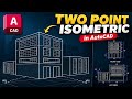
Mastering AutoCAD: A Beginner’s Guide to Essential CAD tools and Commands

Thursday, September 17, 2026

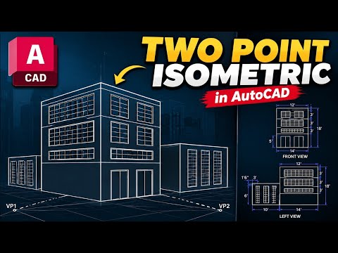
Have you ever looked at a complex architectural blueprint and wondered how such precision is achieved? AutoCAD is the industry-leading software for 2D and 3D design, serving as the backbone for architects, engineers, and designers worldwide. However, for a complete beginner, the interface can often feel overwhelming. The key to success lies in mastering the fundamental CAD tools that form the basis of every professional drawing.

Getting Started with the AutoCAD Interface

Before diving into complex designs, it is crucial to understand that AutoCAD is a command-driven environment. While you can click icons, the most efficient way to work is by using keyboard shortcuts. This approach not only speeds up your workflow but also allows you to focus more on the creative aspect of your project. As you familiarize yourself with the workspace, you will notice that most high-level drafting relies on a handful of core functions.

Essential Drawing Commands

To start your journey, you must master the basic drawing commands. The "Line" (L) command is perhaps the most used feature, allowing you to create straight segments between two points. Similarly, the "Circle" (C) and "Rectangle" (REC) commands allow for the quick generation of geometric shapes. By learning how to input specific coordinates and dimensions into these CAD tools, you ensure that your designs are accurate to the millimeter.

Modifying and Refining Your Designs

Drawing a line is only the beginning; the real power of AutoCAD lies in its modification capabilities. Tools such as "Trim" (TR) allow you to cut overlapping lines, while "Offset" (O) is indispensable for creating parallel lines—perfect for defining wall thicknesses in floor plans. Additionally, the "Mirror" (MI) command can save hours of work by reflecting symmetrical objects across an axis.

Conclusion: Practice Makes Perfect

Mastering AutoCAD is a journey of consistency. By focusing on these primary CAD tools and practicing them daily, you will transform from a novice into a confident drafter. Remember, every complex architectural marvel started with a simple line. Start small, stay curious, and keep practicing your commands to unlock the full potential of digital drafting.

Continue Reading | ความคิดเห็น

Master the Art of Flawless Rendering: How to Achieve Perfectly Flat Walls

Achieving a smooth, professional finish on brickwork is the hallmark of a skilled tradesperson. While many beginners focus solely on the consistency of the mortar mix, the secret to a truly flat surface lies in the tools and the technique used during the leveling phase. If you want to master the art of rendering, understanding the mechanics of the plastering rule is essential.

The Role of the Plastering Rule

A plastering rule, also known as a straight edge or screed, is more than just a piece of metal; it is a precision instrument. Its primary function is to act as a guide that spans across the uneven surface of the wall. When you apply your base coat of mortar, the thickness is rarely uniform. By using a rigid straight edge, you create a mechanical reference point that bridges the "peaks" and "valleys" of the wet material, allowing you to see exactly where the wall needs adjustment.

Technique: Pulling and Leveling

The magic happens in the movement. The rigid straight edge acts like a precision guide as you work. As you pull the rule upward across the wet mortar, the sharp, rigid edge shears off excess material. This action does two things simultaneously: it flattens the high points and reveals where more mortar is needed.

For those serious about high-quality rendering, this step cannot be rushed. You must maintain consistent pressure and a steady angle to ensure the rule doesn’t "dig in" or skip over the surface. The goal is to let the tool do the heavy lifting of identifying imperfections that the human eye might miss.

Achieving the Perfectly Flat Result

Once the excess is removed, you can use that same material to fill in any voids or hollows identified by the straight edge. This cycle of screeding and filling continues until the rule glides across the wall without leaving gaps behind it. This process ensures that your final surface is not just smooth to the touch, but geometrically flat.

Mastering these fundamentals will significantly improve the durability and aesthetic of your masonry work. By treating your straight edge as a precision guide, you ensure that your rendering projects stand the test of time and look flawless under any lighting conditions. Whether you are a DIY enthusiast or a professional looking to sharpen your skills, the key to success is patience and the right tool for the job.

Continue Reading | ความคิดเห็น

Next-Gen Engineering: Top 5 GitHub Repositories for CAD and CAE Software Agents

Wednesday, September 16, 2026

The landscape of mechanical engineering is undergoing a massive digital transformation. As artificial intelligence continues to permeate every industry, the fields of CAD (Computer-Aided Design), CAE (Computer-Aided Engineering), and CAM (Computer-Aided Manufacturing) are seeing a surge in innovation through specialized AI agents. Today, we are diving into the top trending GitHub repositories that are redefining how engineers interact with complex design and simulation tools.

The Rise of Agent-Based Engineering

Traditionally, engineering workflows required significant manual intervention—from setting up boundary conditions to refining meshes. However, the latest "agent skills" appearing on GitHub are changing the game. These repositories provide the logic and frameworks necessary for AI agents to assist in complex tasks, effectively bridging the gap between raw data and actionable engineering insights.

By leveraging these open-source tools, developers can enhance the capabilities of modern CAE software, allowing for automated optimization loops that were previously impossible. Whether you are looking to automate structural analysis or streamline fluid dynamics simulations, these repositories offer a wealth of documented setup paths to get you started quickly.

Streamlining Workflows with Open Source

One of the most significant advantages of these GitHub highlights is their focus on accessibility. Each featured repository provides a clear roadmap for installation and use, ensuring that even those new to AI can begin integrating these "skills" into their existing CAD or CAE software pipelines.

These tools typically focus on: * Automated Geometry Cleanup: Preparing models for simulation without manual clicking. * Optimization Loops: Using AI to iterate through hundreds of design variations to find the lightest or strongest configuration. * Documentation and Setup: Providing clear instructions to ensure the software environment is configured correctly for high-performance computing.

Why Documentation Matters

As highlighted in the latest GitHub countdown, the value of a repository isn't just in its code, but in its usability. The top 5 repositories currently trending are those that prioritize a clear "setup path." This transparency allows engineering firms to evaluate the feasibility of new tools before committing significant resources to them.

As we move toward a more automated future, the integration of AI agents into your primary CAE software will likely become a standard industry practice. Staying ahead of the curve means keeping a close eye on these open-source developments and understanding how agent-based skills can solve your most pressing design challenges.

Continue Reading | ความคิดเห็น

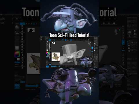
Unlock Efficient 3D Modeling: How Mesh Design and Arrays Work Together

Creating detailed 3D models from scratch can often feel time-consuming and tedious. Fortunately, modern mesh design workflows leverage clever techniques like mesh arrays to streamline the creative process. Whether you are building intricate architecture or sci-fi environments, mastering array tactics will dramatically improve your 3D modeling pipeline.

Building Complexity with Mesh Arrays

What exactly is a mesh array? Instead of manually copying, pasting, and placing individual objects, an array modifier allows you to repeat a single base object multiple times with exact precision. For instance, duplicating a single base mesh 14 times can instantly construct a complex structure—such as a futuristic corridor, a circular staircase, or a detailed industrial railing. By applying smart mesh design principles, you reduce file clutter, lower scene overhead, and save countless hours of manual alignment.

Effortless Editing and Seamless Updates

The real magic of using arrays lies in global editing. When working with linked instances, any tweak applied to the original base mesh automatically propagates across every single repeated instance in your scene.

If you decide to bevel an edge, adjust a vertex, or refine a bevel on the source piece, all 14 instances update instantly in real time. This dynamic approach completely eliminates repetitive design issues, ensuring perfect consistency throughout your entire project without forcing you to redo tedious work.

Elevate Your 3D Modeling Workflow

Don't let repetitive tasks slow down your artistic vision. By adopting array-based mesh design techniques, you can construct complex, highly detailed 3D environments in a fraction of the time while maintaining total editability over your final output. Start implementing mesh arrays today to make your digital design workflow smarter and much more efficient!

Continue Reading | ความคิดเห็น

Parametric vs Non-Parametric Tests | Research Writing Tips for Beginners (5-Minute Series) - Parametric

Technical Overview: Parametric vs Non-Parametric Tests | Research Writing Tips for Beginners (5-Minute Series)

This article provides an in-depth analysis and overview of 'Parametric', covering structural mechanisms and operational workflows to help professionals and enthusiasts understand key parameters and components thoroughly.

In-depth Structural & Operational Analysis

Research Writing Tips for Beginners l 5-Minute Series* ...

Key Takeaways & Summary

Based on the review of 'Parametric vs Non-Parametric Tests | Research Writing Tips for Beginners (5-Minute Series)' regarding 'Parametric', understanding the underlying mechanics and structural components significantly enhances operational efficiency and maintenance practices.

Continue Reading | ความคิดเห็น

Mastering Solid Modeling: A Step-by-Step CATIA V5 Tutorial for Beginners

CATIA V5 remains one of the most powerful and widely used software suites in the aerospace and automotive industries. For aspiring engineers and designers, mastering solid modeling is a fundamental step toward professional proficiency. In this latest installment of our tutorial series, we break down Exercise 32, focusing on the seamless transition from a 2D engineering drawing to a fully realized 3D part.
Transitioning from 2D Drawings to 3D Geometry

The core of any mechanical design starts with a blueprint. Understanding how to interpret dimensions, tolerances, and views is crucial before you even touch the software. In this tutorial, we demonstrate how to analyze a 2D technical drawing and plan your sketching strategy. By identifying the primary features of the part first, you can build a more stable and editable model.

The Core Principles of Solid Modeling

In the world of Computer-Aided Design (CAD), solid modeling is about more than just creating shapes; it is about defining the volume, mass, and physical properties of a component. Using CATIA V5’s Sketcher workbench, we start by creating a "constrained" profile. This ensures that your design remains robust—meaning that if you change a single dimension later, the entire model updates correctly without errors.

Once the 2D sketch is finalized, we utilize essential features such as the Pad tool to extrude material and the Pocket tool to remove it. These boolean-like operations are the building blocks of 3D design, allowing you to sculpt your model with surgical precision.

Refining Your Professional Workflow

To move from a beginner to an intermediate level, you must focus on design intent and tree organization. This tutorial covers how to properly name your features and organize your Part Body. We also explore the application of dress-up features like fillets and chamfers, which provide the final engineering touches necessary for a production-ready model.

Whether you are a student or a professional looking to refresh your skills, practicing these exercises is the most effective way to gain confidence in the software. By the end of this guide, you will have a much stronger grasp of solid modeling and be better prepared to tackle complex industrial design challenges.

Continue Reading | ความคิดเห็น

Model Monday Live SEPT 14 | CAD Speed Modeling Battles, Tutorials, Tips and Tricks - CAD software

Tuesday, September 15, 2026

Technical Overview: Model Monday Live SEPT 14 | CAD Speed Modeling Battles, Tutorials, Tips and Tricks

This article provides an in-depth analysis and overview of 'CAD software', covering structural mechanisms and operational workflows to help professionals and enthusiasts understand key parameters and components thoroughly.

In-depth Structural & Operational Analysis

Think you're the fastest in 3D CAD? Here's you're chance to prove it! Join us for this week's episode of Model Monday, the weekly ...

Key Takeaways & Summary

Based on the review of 'Model Monday Live SEPT 14 | CAD Speed Modeling Battles, Tutorials, Tips and Tricks' regarding 'CAD software', understanding the underlying mechanics and structural components significantly enhances operational efficiency and maintenance practices.

Continue Reading | ความคิดเห็น

Precision Dentistry: How 3D CAD Transforms Dental Crown Design and Stress Analysis

Modern dentistry is undergoing a massive digital transformation, where cutting-edge engineering meets restorative care. Among the most impactful innovations is the integration of advanced 3D CAD technology into crown preparation and biomechanical analysis. By combining precise digital scans with Finite Element Analysis (FEA), dental professionals can now design and evaluate restorations with unprecedented accuracy before ever placing them in a patient's mouth.

Setting the Standard: Precision Margins on Digital Scans

A successful dental crown relies heavily on accurate margin definition. Using high-resolution 3D scans of a molar, practitioners can establish exact preparation boundaries with extreme clarity. This digital foundation eliminates the traditional margins of error associated with conventional physical impressions. By visualizing the exact geometry of the prepared tooth, clinicians ensure an optimal fit, superior marginal integrity, and long-term retention of the crown.

Biomechanical Engineering: The Power of FEA Stress Analysis

Designing an aesthetically pleasing crown is only half the battle; the restoration must also withstand the heavy biomechanical forces of chewing and grinding. This is where modern 3D CAD modeling and Finite Element Analysis (FEA) come into play.

FEA simulates real-world physical stresses directly on the virtual molar and crown model. The analysis highlights areas of high pressure, structural strain, and potential points of material failure. By analyzing stress distribution under various occlusal loads, dental technicians and engineers can refine crown thickness, adjust margin geometry, and select the ideal restorative material tailored to the patient’s specific bite dynamics.

Streamlining the CAD/CAM Dental Workflow

The synergy between digital design and mechanical simulation streamlines the entire CAD/CAM workflow. Instead of relying on trial and error or standardized assumptions, dental teams leverage 3D CAD insights to predict material performance accurately. The results speak for themselves: faster turnaround times, fewer chairside adjustments, and a significantly lower risk of structural crown fractures over time.

As biomechanical stress analysis becomes standard practice, digital crown preparation is setting a new benchmark for predictable, durable, and patient-specific dental care.

Continue Reading | ความคิดเห็น

Seamless CAD Transition: Top AutoCAD Tools Available in DraftSight

Switching CAD software can often feel like a daunting task, especially if your team relies heavily on years of muscle memory built using AutoCAD. Fortunately, making the move to DraftSight is remarkably smooth, offering minimal disruption to your daily design workflows while maximizing software value.

Familiar Command Line and Aliases

One of the biggest hurdles when adopting a new drafting tool is relearning shortcuts and interface layouts. DraftSight eliminates this friction by supporting familiar command line inputs and AutoCAD keyboard aliases. Whether you are drawing lines, offsetting objects, or trimming complex geometry, you can type the same commands you have used for years without missing a beat. The intuitive user interface ensures that veteran CAD users feel right at home from day one.

Seamless Legacy File and LISP Support

Transitioning your design environment doesn't mean leaving your historical data behind. DraftSight allows you to open, edit, and save native DWG and DXF files with total precision and no data loss. Furthermore, for advanced users who depend on automation, DraftSight supports legacy LISP routines and custom scripts. This means your proprietary macros and time-saving automation tools will continue to work seamlessly within the new workspace.

Effortless Integration with Existing Dynamic Blocks

Managing design assets remains straightforward during your software transition. DraftSight fully supports existing block libraries, including complex dynamic blocks. You can insert, manipulate, and modify block attributes just as you normally would, ensuring that your team's standardized libraries remain fully functional and up to date.

Why Make the Move Today?

Upgrading your CAD setup should not force you to sacrifice efficiency or spend weeks retraining your staff. With its flexible licensing models, robust feature set, and high compatibility with industry standards, DraftSight delivers a powerful, cost-effective alternative for 2D drafting and 3D design without requiring you to abandon the CAD tools you trust.

Continue Reading | ความคิดเห็น

Cosmic Directions: Understanding the 3D Geometry of Proxima Centauri

Proxima Centauri, located roughly 4.24 light-years away in the constellation Centaurus, is our solar system's closest stellar neighbor. While it has long fascinated astronomers and space enthusiasts, charting a path to this red dwarf star requires far more than a traditional flat star map. To truly understand where Proxima Centauri sits in relation to Earth, scientists rely on advanced spatial modeling powered by 3D geometry.

Mapping the Stars Beyond Two Dimensions

For centuries, stargazers mapped the night sky using standard two-dimensional coordinates: Right Ascension and Declination. While these measurements work exceptionally well for pointing a backyard telescope, they fall short of capturing the true spatial depth of the universe. Space is vast, deep, and three-dimensional.

By applying 3D geometry to modern astronomical data, researchers can convert flat celestial coordinates into accurate spatial models. This added dimension allows us to calculate not just direction, but the precise distance and physical orientation between Earth, our Sun, and the surrounding stars in the Alpha Centauri system.

Plotting the Cosmic Vector to Proxima Centauri

Determining the exact direction to Proxima Centauri involves calculating a precise three-dimensional vector through space. Astronomers achieve this by combining trigonometric parallax—the subtle shift in a star's apparent position as Earth orbits the Sun—with direct distance measurements.

When these vectors are plotted using 3D geometry, they create an intuitive visual guide of our immediate galactic neighborhood. This spatial perspective clearly illustrates how Earth and Proxima Centauri are situated relative to one another, offering a clear directional path through the cosmic void.

Why 3D Coordinates Matter for Future Exploration

As humanity looks toward interstellar exploration, mastering spatial mapping is becoming increasingly crucial. Concept missions, such as sending ultra-lightweight probes to the Alpha Centauri system, require hyper-accurate trajectory planning. Static 2D maps simply cannot account for long-distance interstellar navigation.

Ultimately, utilizing spatial math bridges the gap between theoretical astronomy and real-world spaceflight. By mapping the universe in three dimensions, we take the first essential steps toward navigating the stars and reaching our nearest celestial neighbors.

Continue Reading | ความคิดเห็น

AutoCAD on the Go: Master Powerful Mobile CAD Tools Easily

Monday, September 14, 2026

The world of computer-aided design has evolved rapidly over the past few years. Gone are the days when engineers, architects, and designers were strictly tied to heavy desktop workstations to create or modify technical drawings. Today, accessing essential CAD tools directly from your smartphone or tablet is not only possible but also surprisingly efficient. The AutoCAD Mobile App brings full-fledged design capabilities right to your fingertips, allowing professionals to stay productive wherever they go.

Why Transition Your CAD Workflow to Mobile?

Working on site or traveling often requires quick adjustments to blueprints, schematics, and floor plans. Carrying a bulky laptop in the field isn't always practical. Mobile drafting applications bridge this gap by offering a portable solution without sacrificing accuracy. With intuitive touch controls, cloud integration, and real-time file syncing, you can open, view, edit, and share DWG files effortlessly from anywhere in the world.

Essential Capabilities and Mobile CAD Tools Explained

The mobile interface is carefully optimized to deliver maximum performance on smaller touchscreen devices while retaining core engineering functionality. By bringing essential CAD tools into a streamlined interface, AutoCAD Mobile enables users to perform complex drafting tasks with ease. Key features include:

  • Precision Drawing & Editing: Easily create lines, polylines, arcs, and polygons using touch controls or a digital stylus for pinpoint accuracy.
  • Layer Management: Control layer visibility, lock critical design elements, and assign distinct colors to keep your drawings structured and readable.
  • Measurement & Annotation: Take quick distance, area, and angle measurements directly on site. Add notes, dimensions, and callouts instantly to communicate revisions.
  • Cloud Synchronization: Connect seamlessly with cloud storage platforms like Google Drive, OneDrive, and Dropbox to ensure your team always works on the latest version.

Tips to Maximize Your Mobile Design Workflow

To get the best experience while drafting on a mobile device, pair your phone or tablet with a responsive stylus for finer control when selecting small vertices and snap points. Additionally, make full use of object snaps and grid lines to ensure your mobile drafts maintain professional, industry-standard accuracy.

Final Thoughts

Mobile CAD drafting is transforming how modern professionals collaborate and execute projects. Whether you are conducting site inspections or drafting preliminary concepts during your commute, mastering these mobile CAD tools will significantly boost your productivity and workplace flexibility.

Continue Reading | ความคิดเห็น

Wuben E19 Review: The Ultimate High CRI Penlight for Precision Color Rendering

When it comes to everyday carry (EDC) gear, bigger isn't always better. Sometimes, the most valuable tool in your pocket is the one that provides clarity and precision where other lights fail. Enter the Wuben E19, a slim and sophisticated penlight that prioritizes light quality over raw power. Whether you are a medical professional, a technician, or a hobbyist, this AAA-powered light is designed to show you the world as it truly is.

Accurate Color Rendering for Professional Use

The standout feature of the Wuben E19 is its high Color Rendering Index (CRI). While standard flashlights often wash out colors or give them a sickly blue tint, the E19 utilizes a specialized LED designed for accuracy. When performing close-up work, the quality of color rendering is just as important as the brightness itself.

With a CRI rating of over 90, this penlight allows you to distinguish between subtle shades of wire, see skin tones accurately, and inspect mechanical parts with confidence. This level of professional-grade color rendering makes the E19 an essential tool for anyone whose job depends on visual accuracy.

Compact Power and Practicality

Despite its slender, pen-like profile, the Wuben E19 isn't lacking in performance. It delivers a maximum output of 200 lumens, which is more than enough for indoor inspections, reading maps, or navigating dark hallways. The beam is balanced—offering a soft hotspot and a usable spill that prevents eye strain during extended use.

One of the most practical aspects of the E19 is its power source. It runs on two standard AAA batteries. This means you never have to worry about proprietary charging cables or waiting for an internal battery to top up. You can find replacements in almost any drawer or convenience store, ensuring your light is always ready for action.

Built for Everyday Carry

The design of the Wuben E19 is both functional and durable. Constructed from high-strength aluminum with a hard-anodized finish, it feels premium in the hand and can withstand the rigors of daily use. It features a simple tail-switch interface that allows for easy one-handed operation, cycling through four brightness levels (including an SOS mode).

The included stainless steel pocket clip ensures it stays securely fastened to your shirt pocket or notebook. Because of its lightweight and slim diameter, you’ll likely forget it’s there until you need it.

Final Verdict

The Wuben E19 is a masterclass in functional design. It moves away from the "lumen wars" to focus on what actually matters for close-up tasks: color accuracy and portability. With its exceptional color rendering abilities and convenient battery setup, it is a top-tier choice for professionals and EDC enthusiasts alike. If you need a reliable light that reveals the true details of your work, the E19 is the perfect addition to your kit.

Continue Reading | ความคิดเห็น

Unlock Your Engineering Potential: Master CAE Software at SDI Bhubaneswar

In today’s rapidly evolving engineering landscape, turning innovative ideas into functional, real-world products requires far more than just traditional drafting skills. It demands a deep understanding of computer-aided design (CAD) and computer-aided engineering (CAE). If you want to jumpstart a successful career in product design and structural analysis, the CAD-CAE Design & Analysis Course at Skill Development Institute (SDI) Bhubaneswar offers an outstanding launchpad.

Why CAD-CAE Skills Matter in Modern Industry

Modern manufacturing and engineering sectors rely heavily on digital prototypes long before physical production begins. By mastering advanced CAE software, engineers can simulate real-world forces, thermal dynamics, and structural integrity under a variety of operating conditions. This digital-first approach significantly cuts down development costs, minimizes material waste, and accelerates product delivery schedules. Learning how to navigate these sophisticated digital tools bridges the gap between classroom theory and practical, high-demand workforce skills.

Hands-On Training at SDI Bhubaneswar

The specialized CAD-CAE program at SDI Bhubaneswar is meticulously designed to align with current industrial demands. Students gain essential practical experience using industry-grade tools and high-performance CAE software to solve complex design challenges. From 3D geometry creation to finite element analysis (FEA), the comprehensive curriculum ensures learners walk away with real-world competence.

Key benefits of the course include: - In-depth instruction on leading CAD modeling platforms. - Practical simulation and structural evaluation workflows using modern CAE software. - Expert mentorship from seasoned industry professionals in state-of-the-art facilities. - Project-based learning that empowers you to build a job-ready portfolio.

Take the Next Step in Your Engineering Career

Whether you are a fresh engineering graduate aiming to boost your employability or a working technician looking to upskill, mastering CAD and CAE methodologies is one of the smartest career moves you can make. SDI Bhubaneswar provides the ultimate ecosystem, expert guidance, and technical resources to help you thrive. Step into the future of design and analysis today!

Continue Reading | ความคิดเห็น

How to Create Stunning Modern Texture Art with Mesh Design

Sunday, September 13, 2026

Not every powerful visual effect relies heavily on vibrant colors. Sometimes, it is the raw texture and intricate relief work that truly brings a painting to life. If you want to elevate your modern canvas art, incorporating tactile elements is one of the most effective ways to captivate viewers. In this guide, we will explore how you can create a striking piece of modern art using a unique, structured technique.

The Power of Texture in Modern Canvas Art

While color sets the mood, texture creates dimension and intrigue. High-relief artwork catches light differently throughout the day, constantly changing how the piece looks from various angles. By introducing a structured mesh design into your canvas work, you create an eye-catching focal point that invites viewers to look closer and feel the depth of the artwork.

Step-by-Step: Crafting a Dynamic Grid Structure

Creating a modern textured painting does not require decades of technical fine-art training, but it does demand patience and the right materials. Here is how you can build a captivating structural masterpiece:

  1. Prepare Your Base: Start with a sturdy canvas that can handle heavier structural mediums like paste, modeling compound, or acrylic gels.
  2. Apply the Structural Paste: Use a palette knife or trowel to spread your paste evenly across the sections where you want your pattern to sit.
  3. Form the Pattern: Carefully press your netting material or stencil into the wet paste to imprint a subtle mesh design. Lift it cleanly away to reveal crisp, raised lines.
  4. Refine and Highlight: Once the medium is fully dry, layer soft neutral paints or metallic highlights over the high points to accentuate the raised geometry.

Elevating Your Artwork with Subtle Accents

The secret to successful modern texture art lies in restraint. You do not need to cover the entire canvas in heavy patterns. Instead, allow your detailed mesh design to contrast naturally with smooth, negative spaces. This balance creates a harmonious visual rhythm that feels refined, contemporary, and sophisticated.

Whether you are an aspiring artist or an experienced painter looking to experiment with new techniques, working with geometric structures and net patterns will add a dynamic new dimension to your creative process.

Continue Reading | ความคิดเห็น

How to Create Parametric Equipment Symbols in BricsCAD for Intergraph Smart 3D

In the world of industrial plant design, speed, precision, and software interoperability are crucial. Combining the robust drafting capabilities of BricsCAD with the industry-standard execution of Intergraph Smart 3D offers engineers an unbeatably efficient modeling workflow.

If you want to streamline your equipment creation process, learning how to build and deploy intelligent models between these platforms is key. Here is a practical overview of how to build a vertical vessel symbol in BricsCAD and export it straight into Smart 3D.

Step 1: Designing a Parametric Vertical Vessel in BricsCAD

Creating custom equipment shapes from scratch for every project can be time-consuming. However, by leveraging parametric modeling techniques within BricsCAD, designers can define flexible geometric constraints and dimensional parameters for complex components like Vertical Vessels.

Instead of redrawing equipment whenever project specifications change, a single dynamic model can adapt to varying heights, diameters, and nozzle placements instantly. BricsCAD provides an intuitive environment for setting up these rules, ensuring your 3D models remain versatile and easy to update.

Step 2: Seamless Integration into Intergraph Smart 3D

Once your vessel symbol is configured, the next step is deploying it into Intergraph Smart 3D. Traditional file conversions often lead to lost metadata or static, non-editable shapes.

Fortunately, direct deployment methodologies allow you to transfer the component while preserving its intelligence. By importing your parametric symbols directly into Smart 3D's catalog environment, your engineering team gains access to rich equipment assets ready for piping, layout, and structural placement without starting from scratch.

Key Benefits for Plant Design Workflows

Integrating BricsCAD dynamic symbols into your Smart 3D ecosystem delivers several immediate advantages: * Enhanced Efficiency: Utilizing parametric components eliminates repetitive modeling tasks, saving hours of manual labor. * Data Consistency: Assets retain vital dimensional data and connection attributes needed for downstream piping workflows. * Design Flexibility: Quick adjustments can be made at any stage of the detailed engineering phase without compromising project timelines.

Final Thoughts

Bridging the gap between preliminary CAD design and comprehensive plant execution doesn't have to be complicated. By mastering the workflow from BricsCAD to Intergraph Smart 3D, you empower your engineering team with scalable, intelligent equipment symbols that boost productivity across every project.

Continue Reading | ความคิดเห็น

The Return of Nazdreg: How Solid Modeling Revived the Classic Ork Warboss

Warhammer 40,000 collectors and Ork players have a massive reason to celebrate. Nazdreg Ug Urdgrub, the legendary Warboss of the Bad Moons clan, is officially back with a brand-new miniature. Having not seen a fresh sculpt since 2nd Edition, this iconic Ork leader has finally stepped into the modern era of tabletop gaming with an incredible, imposing look.

A Modern Transformation Powered by Solid Modeling

The evolution from Nazdreg’s classic metal sculpt to his current release demonstrates how drastically miniature design has advanced over the decades. Through modern solid modeling processes, sculptors have managed to capture the classic, heavy-set silhouette of the Bad Moons leader while dramatically improving his scale, stance, and structural detail. The new sculpt strikes a perfect balance between nostalgic homage and cutting-edge miniature engineering.

Intricate Details and Unmatched Bad Moons Aesthetic

As any Ork fan knows, Nazdreg is defined by his vast wealth and love for high-end dakka. His updated miniature truly reflects his rich lore. Utilizing state-of-the-art solid modeling, designers rendered complex layers on his Mega Armour, complete with crude mechanical upgrades, custom bolt-work, and signature Bad Moons glyphs. His massive Kustom Mega-Blasta looks terrifyingly powerful, paired alongside a menacing Power Klaw that makes him look ready to crush any enemy on the battlefield.

Why Nazdreg’s Return is a Game-Changer

For years, Nazdreg remained a beloved figure largely confined to retro codexes and lore books. His triumphant return brings hope to long-time hobbyists wanting to see classic characters reworked for modern play. This release proves that expertly executed solid modeling can revive legacy heroes without losing the grimdark soul that makes Warhammer 40k so compelling. Whether you are a dedicated greenskin commander or a miniature painting enthusiast, Nazdreg’s new model is a solid addition to any collection.

Continue Reading | ความคิดเห็น

Mastering Advanced Sketching: Pro Tips and Tricks for CAD Software Users

Sketching is the fundamental building block of any 3D model. Whether you are designing a simple bracket or a complex mechanical assembly, the efficiency and stability of your final product depend heavily on how you approach the initial 2D layout. For professionals and hobbyists alike, mastering the nuances of your CAD software is the secret to moving from basic designs to high-level engineering.

Rethinking Your Sketching Strategy

Many users fall into the habit of using the same basic tools for every project. However, advanced sketching is about more than just drawing lines and circles; it is about intent and flexibility. Instead of manually dimensioning every single entity, advanced users leverage geometric relations to define how shapes interact. By "thinking a different way," you can create sketches that are easier to modify later, preventing your model from "breaking" when a single dimension changes.

Efficiency Through Advanced Techniques

When working with professional-grade CAD software, speed is often just as important as accuracy. One of the best ways to improve your workflow is to utilize shortcut keys and mouse gestures for common sketch entities. Furthermore, exploring non-traditional methods—such as using construction geometry to drive complex patterns or employing the "Path Length" dimension—can solve design challenges that standard sketching simply cannot handle.

Another "pro tip" involves minimizing the number of entities in a single sketch. By breaking complex parts into several simpler features, you maintain better control over the design intent. This modular approach is a hallmark of an expert user who knows how to harness the full potential of their digital tools.

Why Mastering These Skills Matters

The transition from a beginner to an advanced user requires a shift in mindset. It’s about understanding the underlying logic of the program. By mastering these advanced tips and tricks, you aren't just drawing; you are programmatically defining a physical object.

As you continue to refine your skills within your CAD software, you will find that your design process becomes more intuitive and significantly faster. This not only makes you a more valuable engineer or designer but also allows you to focus more on the creative aspects of innovation rather than the technical hurdles of the interface. Keep experimenting with different sketching methods, and you will soon see a massive improvement in your 3D modeling precision.

Continue Reading | ความคิดเห็น

Mastering 3D CAD: The Ultimate Beginner’s Guide to Cloud-Based Onshape

Saturday, September 12, 2026

Are you ready to transform your creative concepts into tangible objects? Whether you are a hobbyist, an aspiring engineer, or a product designer, the world of digital design has never been more accessible. In this guide, we dive deep into Onshape, a revolutionary platform that is changing how we approach 3D CAD by moving the entire design process into the cloud.

Why Choose Cloud-Based Design?

Traditional design software often requires expensive hardware and complex installations. Onshape breaks these barriers by operating entirely within your web browser. This means you can access your projects from any device, anywhere in the world, without worrying about software versions or local storage. For those just starting their journey in 3D CAD, this accessibility removes the technical friction often associated with professional-grade engineering software.

Mastering the Basics of Onshape

In this second part of our beginner's series, we move beyond the interface and start building. Onshape’s power lies in its parametric modeling capabilities. This allows you to create designs based on constraints and dimensions, ensuring that every part fits perfectly within a larger assembly.

The workflow typically follows a logical progression: 1. Sketching: Creating the 2D foundation of your part. 2. Constraints: Defining relationships between lines and points to ensure stability. 3. Features: Using tools like "Extrude," "Revolve," or "Fillet" to turn those 2D sketches into 3D objects.

By mastering these fundamental steps, you gain the confidence to tackle more complex geometries and multi-part assemblies.

From Concept to Reality

The true magic of 3D CAD lies in its ability to bridge the gap between imagination and manufacturing. Once your model is complete in Onshape, it can be easily exported for 3D printing, CNC machining, or laser cutting. Because the software is cloud-based, collaboration is built into its DNA; you can share your documents with a single click, allowing for real-time feedback and teamwork.

As you continue to practice, you will find that 3D modeling is not just about drawing—it’s about problem-solving. Every sketch and feature is a step toward bringing your unique ideas to life. Stick with the process, keep experimenting with the tools, and you’ll be amazed at what you can create.

Continue Reading | ความคิดเห็น

Mastering Onshape: The Ultimate Beginner's Guide to Cloud-Based 3D CAD

Are you ready to transform your creative ideas into digital reality? Modern product design and engineering have evolved rapidly, moving away from heavy, desktop-bound software toward streamlined, cloud-based solutions. If you are just starting your design journey, learning a powerful 3D CAD platform like Onshape is one of the best ways to kickstart your skill set.

In this beginner-friendly guide, we explore how Onshape simplifies the design workflow and why browser-based modeling is revolutionizing the industry.

Why Choose Onshape for Cloud-Based Modeling?

Traditional design software often requires high-end graphics hardware, complex installation procedures, and messy file management. Onshape changes the game by operating entirely inside your web browser. This means you can access your projects from virtually any computer or tablet without worrying about software updates or lost files.

Key advantages include: - Real-Time Collaboration: Work on projects simultaneously with team members, much like Google Docs. - Automatic Version Control: Every change is saved instantly, eliminating the fear of losing progress or overwriting critical revisions. - Zero Installation: Open your browser, log in, and start modeling immediately from anywhere.

Essential Workflow in Cloud-Based 3D CAD

Mastering 3D CAD is much easier when you understand the basic design lifecycle. In Onshape, your workflow generally follows a clear, logical sequence:

  1. 2D Sketching: Begin by selecting a design plane (Top, Front, or Right) and creating 2D profiles using essential shapes like lines, circles, and rectangles.
  2. Applying Constraints: Define precise dimensions and geometric relationships so your sketch behaves predictably when adjusted.
  3. 3D Feature Creation: Convert your 2D sketch into a solid 3D object using primary tools like Extrude, Revolve, or Fillet.
  4. Assembly and Testing: Combine multiple parts together to see how they fit and move relative to one another.

Ready to Elevate Your Design Skills?

Whether you want to create custom parts for 3D printing, conceptualize consumer products, or build a foundation for an engineering career, mastering 3D CAD opens up endless possibilities. Start experimenting with simple shapes today, practice regularly, and watch your creative ideas come to life in the cloud!

Continue Reading | ความคิดเห็น

How to Easily Inspect Complex 3D CAD Assemblies Without Heavy Software

Opening complex engineering files often presents a major hurdle for non-designers, project managers, and client stakeholders. Traditionally, inspecting intricate design files required high-end hardware and expensive, specialized software installations. However, modern cloud technology is changing the game, making it simpler than ever to view and analyze 3D CAD models directly within your web browser.

Browser-Based CAD Inspection Made Simple

With cloud-native platforms like CAD ROOMS, inspecting detailed CAD assemblies no longer requires heavyweight desktop applications. You can open, rotate, zoom, and inspect complex assemblies effortlessly from virtually any device—whether it’s a desktop, laptop, or tablet.

By removing the barrier of software installation, teams can instantly review designs, double-check measurements, and verify assembly structures without waiting for file conversions or managing bulky software updates. This seamless access opens up new possibilities for frictionless cross-departmental collaboration.

Key Advantages for Modern Engineering Teams

Moving your inspection workflow to the browser provides several crucial benefits:

  • Zero Installation Required: Access your models instantly without downloading heavy software or managing licenses across multiple devices.
  • Cross-Platform Flexibility: Whether you are on Windows, macOS, or a mobile operating system, browser-based inspection ensures universal compatibility.
  • Enhanced Collaboration: Share interactive models with clients, suppliers, and internal teams without worrying about whether they have the right viewer installed.
  • Smooth Performance: Process and inspect massive 3D CAD assemblies effortlessly, backed by efficient cloud rendering technologies.

Streamline Your Review Workflow Today

Whether you are an engineer looking to quickly verify a design component or a project manager presenting a concept to clients, cloud-based inspection tools offer the speed and flexibility modern workflows demand. By viewing 3D CAD files directly in the browser, you eliminate technical friction, save valuable time, and keep your projects moving forward seamlessly.

Continue Reading | ความคิดเห็น

The Future of Engineering: Revolutionizing 3D CAD with Text-to-AI

Imagine sitting at your computer and typing, “A 50mm mounting bracket with four symmetrical bolt holes,” and watching a fully functional engineering file appear before your eyes. This isn't science fiction anymore. The emergence of "Text-to-CAD" technology is fundamentally shifting how we approach mechanical design and manufacturing.

For decades, the barrier to entry for professional design has been high. Learning complex software was a prerequisite for turning an idea into a physical object. However, with the integration of Generative AI, the process is becoming as simple as having a conversation. By leveraging natural language processing, designers can now describe mechanical parts in plain English, allowing AI to handle the heavy lifting of geometry generation.

Bridging the Gap Between Concept and Creation

One of the most significant advantages of this technology is the speed of iteration. Traditionally, creating a professional 3D CAD model required hours of technical skill, precise manual input, and a deep understanding of parametric constraints. Now, engineers can generate initial prototypes in seconds. This allows for rapid experimentation, where multiple variations of a part can be tested and refined without the time-intensive process of manual drafting.

Democratizing Professional Design

Furthermore, this AI-driven approach democratizes the design process. Small businesses and hobbyists who may not have mastered professional-grade software can now produce high-quality, manufacturable assets. The ability to generate accurate 3D CAD files from a simple text prompt means that the gap between a concept and a physical prototype has never been smaller. It levels the playing field, allowing the focus to shift from "how to use the tool" to "how to solve the problem."

The Next Frontier of Manufacturing

While we are still in the early stages, the implications for the manufacturing industry are massive. We are moving toward a world where AI doesn't just assist the designer but acts as a collaborative partner. As these models become more sophisticated, they will eventually account for material properties, stress points, and specific manufacturing constraints automatically.

The era of manual sketching is evolving. By embracing AI, we are unlocking a more intuitive and efficient way to build the world around us. Whether you are a seasoned engineer or a curious maker, the fusion of AI and 3D CAD is a frontier that promises to redefine the limits of human productivity.

Continue Reading | ความคิดเห็น

Mastering Tunnel Design: A Step-by-Step Guide Using 3D CAD and Civil 3D

Designing a tunnel is often considered one of the most complex challenges in the fields of civil engineering and surveying. From managing underground clearances to ensuring structural integrity, the process demands an incredibly high level of precision. Fortunately, modern 3D CAD technology has revolutionized how we approach these projects. By utilizing Autodesk Civil 3D, engineers can transform complex data into accurate, data-rich models that streamline the entire construction workflow.

Defining the Path: Alignments and Profiles

The first step in any tunnel project within a 3D CAD environment is establishing a precise horizontal alignment and vertical profile. In Civil 3D, this involves more than just drawing lines; it is about creating a dynamic path that reflects the existing terrain and the specific depth requirements of the underground structure. These parameters serve as the backbone of your model, ensuring that every subsequent step—from structural modeling to volume calculations—is anchored to an accurate geometric reference.

The Power of Assemblies in Tunneling

What truly sets tunnel design apart from standard road design is the "Assembly." In Civil 3D, the assembly represents the cross-section of your tunnel. This includes the structural lining, waterproofing layers, and internal infrastructure such as ventilation, lighting, and drainage systems. Utilizing advanced 3D CAD tools allows you to customize these subassemblies to fit various shapes—whether you are designing a circular TBM (Tunnel Boring Machine) section, a horseshoe shape, or a rectangular box culvert. This flexibility is crucial for adapting to different geological conditions and specific engineering requirements.

Generating the Corridor and Final Visualization

Once the alignment, profile, and assembly are finalized, you can generate the "Corridor." This is the stage where your tunnel design truly comes to life in a three-dimensional space. The corridor integrates all your design data to create a comprehensive model that can be used for cross-section extraction, material takeoff, and clash detection.

By visualizing the tunnel within a professional 3D CAD framework, you can identify potential design flaws or utility conflicts long before the construction phase begins. Mastering these workflows in Civil 3D not only improves your efficiency as a designer but also ensures the highest level of accuracy for large-scale infrastructure projects. Whether you are a seasoned surveyor or a civil engineering student, learning these steps is essential for staying competitive in the modern industry.

Continue Reading | ความคิดเห็น

From Design to Print: How to Resolve Accuracy Issues Between 3D CAD and Slicers

Friday, September 11, 2026

In the world of professional engineering and product design, precision is everything. You spend hours perfecting a model, ensuring every dimension is exact down to the micron. However, many creators face a frustrating hurdle: the discrepancy between the original digital model and the final sliced file. Bridging this gap is essential for anyone looking to transition from hobbyist printing to professional-grade manufacturing.

Understanding the Discrepancy

The journey from a 3D CAD environment to a physical object involves several translations. When you export your design—typically as an STL or STEP file—and import it into a slicer, the software must interpret geometric data into G-code. During this process, "rounding errors" or mesh approximations can occur. If your export settings are too low, a perfectly smooth curve in your design software might become a series of jagged facets in the slicer, leading to dimensional inaccuracies that can ruin a professional assembly.

Calibration is Key

To ensure your physical output matches your 3D CAD intent, you must account for material shrinkage and machine tolerances. Professional projects often require "designing for the process." This means testing how your specific printer and filament react. If a bolt needs to fit into a hole, you may need to apply a small offset in your modeling stage to compensate for the way the plastic expands or contracts during the cooling phase.

Optimizing Your Workflow for Professional Results

For those handling complex projects, such as integrated PCB housings or mechanical enclosures, using high-quality fabrication services can eliminate much of the guesswork. Services like PCBWay offer professional 3D printing and PCB assembly that utilize industrial-grade equipment capable of much tighter tolerances than standard desktop units.

When preparing your files, always export at the highest sensible resolution and double-check your unit scales (mm vs. inches) before hitting the "Slice" button. By syncing your 3D CAD settings with your slicer’s specific capabilities, you can ensure that the "real-world" product is a perfect reflection of your digital vision.

Conclusion

Solving the delta between a model and a print is what separates a prototype from a finished product. By understanding how slicers interpret geometry and adjusting your design workflow accordingly, you can achieve professional-level accuracy every time. Whether you are printing in-house or outsourcing to a factory, precision starts with a well-optimized file.

Continue Reading | ความคิดเห็น

Unlocking the Power of 3D CAD: Quick AutoCAD Tricks Every Designer Should Know

In today’s fast-paced engineering and architectural industries, digital drafting is no longer just about 2D lines and basic shapes. Mastering 3D CAD software like AutoCAD has become an essential skill for professionals looking to bring complex ideas to life with precision and speed. Whether you are a beginner or a seasoned designer, optimizing your workflow can make a massive difference in your daily productivity.

Why 3D CAD Skills Matter in Modern Design

Transitioning from traditional 2D drafting to 3D CAD modeling opens up endless possibilities. It allows designers to visualize spatial relationships, detect structural errors early in the planning phase, and produce photo-realistic renders for clients. Beyond aesthetics, working in three dimensions ensures greater accuracy, making project handoffs smoother across multidisciplinary teams.

Essential AutoCAD Productivity Hacks

To create stunning models efficiently, you don't just need knowledge—you need speed. Here are a few quick tips to streamline your AutoCAD workflow:

  • Utilize Key Command Shortcuts: Relying on keyboard shortcuts like EXT (Extrude), PRESSPULL, and UNION saves valuable time compared to navigating menu icons manually.
  • Master Visual Styles: Switch seamlessly between Conceptual, Shaded, and Realistic views to inspect your model's geometry without slowing down system performance.
  • Implement Dynamic Blocks: Create parametric components that can be resized or altered quickly without redrawing elements from scratch.
  • Use the ViewCube Efficiently: Navigate your workspace effortlessly by customizing your ViewCube settings for fast orientation and angle adjustments.

Elevate Your Design Potential

Integrating these quick habits into your daily routine will drastically reduce drafting time while improving the quality of your output. As 3D CAD technology continues to evolve, staying updated with efficient modeling techniques will keep you ahead of the curve in the competitive design landscape. Start practicing these tricks today and transform your AutoCAD project workflow!

Continue Reading | ความคิดเห็น

Download ABB IRB 460 3D CAD Model | Compact Palletizing Robot

Preview Image

Integrate high-speed automation into your engineering projects with the ABB IRB 460 3D CAD Model. Renowned as one of the world's fastest 4-axis compact palletizing industrial robots, the IRB 460 is widely used in packaging, material handling, and end-of-line industrial automation systems.

Key Features & Specifications:

  • Multi-CAD Compatibility: Available in neutral and native CAD formats suitable for SolidWorks, Autodesk Inventor, CATIA, PTC Creo, Siemens NX, AutoCAD, Pro/ENGINEER, and ACIS (.SAT).
  • Precision Modeling: Highly detailed geometry perfect for robotic cell layout design, reachability analysis, collision detection, and digital twin simulations.
  • Application Utility: Essential asset for automation system integrators, mechanical design engineers, and industrial process planners.

Streamline your robotic cell modeling and reduce design cycle times by incorporating this 3D CAD asset directly into your engineering workspace.


Continue Reading | ความคิดเห็น

From 3D CAD Design to Finished Product: The Plastic Manufacturing Journey

Every innovative plastic component begins with a vision, typically brought to life as a digital prototype. But how exactly does a product transition from a 3D CAD file on a screen to a flawless, high-precision component ready for the market?

Whether you are developing parts for the automotive, electronics, or consumer goods industries, understanding the step-by-step journey from design to mass production is essential for optimizing manufacturing costs, component quality, and time-to-market.

Step 1: Optimizing the Design for Manufacturability

The transition begins with a thorough Design for Manufacturability (DFM) analysis. Expert engineers evaluate the original 3D CAD model to refine wall thickness, incorporate proper draft angles, and optimize gate locations. Identifying and fixing potential defects at this digital stage prevents costly tool modifications later in the production cycle.

Step 2: High-Precision Mold Creation

Once the digital blueprint is finalized, master toolmakers turn the software model into physical steel or aluminum tooling. Utilizing advanced CNC machining and EDM (Electrical Discharge Machining), high-precision molds are crafted to mirror the exact geometry of the intended part. Tooling precision here guarantees consistent quality across thousands—or even millions—of production cycles.

Step 3: The Injection Molding Process

With the custom mold clamped inside an industrial injection molding machine, the manufacturing process takes place in three quick phases: 1. Melting: Raw thermoplastic resin pellets are fed into a heated barrel and melted into a uniform liquid. 2. Injection: The molten polymer is injected under high pressure into the mold cavity, filling every intricate detail of the design. 3. Cooling & Ejection: The plastic rapidly cools and solidifies before ejector pins safely push the finished part out of the mold.

Step 4: Quality Assurance and Post-Processing

After ejection, components undergo rigorous quality checks to verify dimensional accuracy against the source file. Secondary operations—such as surface finishing, custom painting, or automated assembly—are then performed to meet strict industry standards.

Bring Your Vision to Life

Turning complex digital concepts into high-performance plastic parts requires expert tooling and precision molding capabilities. By partnering with specialist manufacturers in high-precision molds and plastic injection molding, businesses in the automotive, electronics, and consumer sectors can effortlessly transform their 3D CAD concepts into market-ready physical products.

Continue Reading | ความคิดเห็น

ABB IRB 2600ID-8/2.00 Industrial Robot 3D CAD Model Free Download

Preview Image

Enhance your automated cell design and simulation workflows with the official 3D CAD model of the ABB IRB 2600ID-8/2.00 industrial robot arm. Featuring Integrated Dressing (ID) technology, this highly versatile 6-axis manipulator is engineered for high-precision applications including arc welding, material handling, and machine tending.

Key Technical Specifications:

  • Payload Capacity: 8 kg
  • Reach: 2.00 meters
  • Axis Count: 6-axis articulated manipulator
  • Design Advantage: Integrated hose package inside the upper arm and wrist for extended process cable life and compact footprint footprint clearance.

Supported CAD Software Formats:

This 3D model is compatible with all major parametric and direct modeling software platforms, including:

  • SolidWorks (.SLDPRT, .SLDASM)
  • AutoCAD (.DWG, .DXF)
  • Autodesk Inventor (.IPT, .IAM)
  • PTC Creo / Pro/ENGINEER (.PRT, .ASM)
  • Siemens NX & Solid Edge
  • CATIA V5/V6
  • Universal Formats: STEP (.stp), IGES (.igs), ACIS (.sat)

Download this accurate CAD file to streamline your robotic system integration, collision detection, and plant layout simulation today.


Continue Reading | ความคิดเห็น

Mastering 3D CAD: How to Model a Mechanical Mounting Bracket in AutoCAD

In the evolving world of mechanical engineering, the ability to transform a 2D concept into a functional 3D model is an essential skill. One of the best ways to sharpen these skills is through practical, hands-on exercises that replicate real-world components. In this guide, we explore the process of creating a mechanical mounting bracket, a fundamental tool in the world of 3D CAD.

Starting with the Foundation: The Base Plate

Every great mechanical model begins with a solid foundation. For this mounting bracket project, we start by constructing a rectangular base plate. In AutoCAD, this involves using primitive shapes or extruding a 2D rectangle to a specific thickness. By assigning a distinct color—such as a vibrant red—designers can easily differentiate between various components within a complex assembly. This level of visual clarity is one of the many advantages of using professional 3D CAD software for mechanical practice.

Precision Engineering and Mounting Holes

A mounting bracket is only as functional as its connectivity. The next critical step in the modeling process is the addition of four precise mounting holes located at the corners of the base. This requires careful measurement and the use of the "Subtract" command to create clean, accurate voids. This stage of the project emphasizes the importance of geometric constraints and precision, ensuring that the digital part would theoretically fit perfectly into a real-world mechanical assembly.

Why Practice Work is Essential

Whether you are a student or an aspiring engineer, consistent practice is the key to proficiency. Transitioning from basic shapes to complex mechanical parts helps users understand the workspace, the Z-axis, and the various shortcuts that speed up the design process. Utilizing 3D CAD for these practice sessions allows you to experiment with different materials, lighting, and viewing angles before moving on to more intricate industrial designs.

Conclusion

Modeling a mechanical mounting bracket is more than just a basic exercise; it is a stepping stone to mastering industrial design. By following these fundamental principles in AutoCAD, you can build a strong portfolio of mechanical parts and gain the confidence needed to tackle large-scale engineering projects. Keep practicing, keep designing, and unlock the full potential of your technical creativity!

Continue Reading | ความคิดเห็น

ABB IRB 1600ID 6-Axis Industrial Robot 3D CAD Model

Preview Image

Download ABB IRB 1600ID 6-Axis Industrial Robot CAD Model

Optimize your automated manufacturing cell simulations and machinery layouts with the ABB IRB 1600ID 6-axis industrial robot 3D CAD model. Featuring Integrated Dressing (ID), the IRB 1600ID is designed specifically for high-precision arc welding, material handling, and tight-space manufacturing applications.

Key CAD Model Features:

  • High Precision Geometry: Accurately modeled 6-axis articulation suitable for reachability and collision detection analysis.
  • Integrated Process Cable Routing: Internal hose package routing for accurate digital twin representation.
  • Universal Integration: Ready for import into all major CAD, CAM, and simulation platforms.

Supported File Formats:

This model is compatible with top CAD systems including SolidWorks, Autodesk Inventor, AutoCAD, PTC Creo (Pro/ENGINEER), Siemens NX, CATIA, ACIS (.sat), STEP, and IGES.

Applications:

  • Robotic workcell layout and reach analysis
  • Tooling and fixture integration
  • Factory automation and digital twin simulation

Continue Reading | ความคิดเห็น

Popular Posts Today

 
Support : 3Dcadbrowser | Grabcad | 3Dcontentcentral | D | E | F | G
Copyright © 2028. Engineering 3DCad Appication - All Rights Reserved