Cad 3D Category

Showing posts with label CAD Design. Show all posts

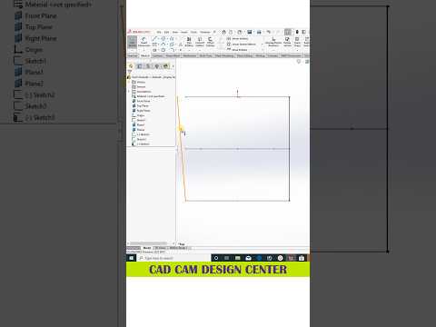
Getting Started with SolidWorks 3D: A Beginner’s Guide to Isometric Modeling

Wednesday, September 30, 2026
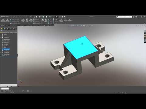
Whether you are an aspiring mechanical engineer, a product designer, or a 3D printing enthusiast, learning computer-aided design (CAD) is an essential skill. Among the leading tools in the industry, SolidWorks 3D stands out for its powerful parametric features and intuitive user interface. In this beginner-friendly guide, we will explore the fundamentals of isometric 3D modeling and show you how to turn basic 2D concepts into detailed three-dimensional models.

What is Isometric 3D Modeling?

Isometric modeling allows designers to represent three-dimensional objects clearly on a two-dimensional plane. Unlike perspective drawings, isometric views maintain parallel lines, making it significantly easier to measure dimensions accurately and visualize the spatial relationships between different features of a component. Mastering this technique provides a strong foundation for technical drawings, complex engineering assemblies, and rapid prototyping.

Core Steps to Create Your First Model

Getting started with SolidWorks 3D does not have to be overwhelming. By following a structured workflow, you can build clean, fully constrained models in just a few straightforward steps:

  1. Select the Orientation: Begin by choosing the appropriate reference plane (Front, Top, or Right) based on how your object will be viewed or manufactured.
  2. Draft the Base Sketch: Use basic geometry tools like lines, rectangles, and arcs to outline the primary shape. Always anchor your sketch to the origin point to maintain design stability.
  3. Apply Smart Dimensions and Constraints: Define precise measurements and geometric relations (such as parallel, perpendicular, or concentric) so your sketch is fully defined.
  4. Extrude into 3D: Use the Extruded Boss/Base feature to transform your 2D outline into a solid 3D object by specifying the required depth.
  5. Refine the Design: Add secondary features such as fillets, chamfers, or extruded cuts to finalize the detailed geometry of your part.

Key Practices for CAD Beginners

To maximize your modeling efficiency when using SolidWorks 3D, keep your initial sketches as simple as possible. It is always better to build up a complex part through multiple simple features rather than creating one overly complicated sketch. Furthermore, utilizing geometric relations instead of excessive manual dimensioning will save you valuable time when making future design revisions.

Start practicing today by recreating basic isometric shapes, and lay the groundwork for your journey into advanced 3D design!


Continue Reading | ความคิดเห็น

Hands-Free CAD: How I Used AI for Fusion 360 3D Modeling and Printing

Monday, September 28, 2026

Imagine stepping away from your mouse and keyboard, letting Artificial Intelligence take the driver’s seat in your CAD workflow. It sounds like science fiction, but combining generative AI with Fusion 360 3D design is changing how makers, engineers, and digital artists approach modeling today.

In my latest project, I decided to test this futuristic workflow by letting AI handle the heavy lifting of designing custom lamps, which were then brought to life using a 3D printer. Here is how AI and modern CAD software come together to redefine physical product design.

Stepping Away from the Mouse: How AI Meets CAD

Traditional CAD design often requires hours of manual sketching, extruding, and tweaking parameters to get complex geometry just right. However, modern AI algorithms can analyze prompts or functional parameters to suggest intricate shapes and structural patterns in seconds.

By feeding specific aesthetic and functional instructions into AI tools, I was able to generate complex parametric light fixture concepts. Instead of spending hours plotting curves manually, the AI established the foundational geometry, allowing me to refine and optimize the result inside the Fusion 360 3D environment. This hybrid approach significantly reduces development time while opening doors to organic designs that are typically difficult to draft from scratch.

From Digital Render to Physical Light

Once the AI-assisted model reached perfection, the next step was turning digital vectors into physical reality. Designing a lamp comes with practical challenges: you must balance aesthetic appeal with functional requirements like wall thickness, heat ventilation, and light diffusion.

Exporting the finalized model from the Fusion 360 3D workspace into slicing software was seamless. The dimensional precision of CAD paired with the unique aesthetics generated by AI created a finished product that looks both modern and artistic. Once sent to the 3D printer, layer by layer, the glowing luminaire came to life.

Is AI the Future of 3D Design?

While AI won't completely replace human creators, it serves as an incredibly powerful co-pilot. Combining AI-driven creative inspiration with robust technical software allows makers to bypass creative block, speed up prototyping, and push the boundaries of additive manufacturing.

Are you ready to experiment with AI in your next project? Step out of your traditional workflow, leverage smart automation, and see what you can create!

Continue Reading | ความคิดเห็น

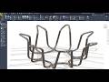
Mastering Precision Design: How to Create a Crown Wireframe Structure in Inventor 3D

Saturday, September 19, 2026

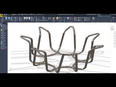
When it comes to high-level mechanical design and intricate geometric modeling, Autodesk Inventor remains a top-tier choice for engineers and designers worldwide. In this guide, we dive into Exercise 227, focusing on the creation of a sophisticated crown-shaped wireframe structure. This particular exercise is designed to test your precision and help you master complex sketching techniques within the software environment.

The Power of Wireframe Modeling

Wireframe structures are the backbone of many advanced industrial designs. Unlike solid modeling, a wireframe focuses on the skeleton of the object, defining the edges and vertices that form its volume. Creating a crown-shaped structure requires a deep understanding of 3D sketching and constraints. By using Inventor 3D, designers can create a series of interconnected paths that represent the delicate yet strong curves of a crown, ensuring that every angle is mathematically accurate.

Key Steps in the Design Process

To begin the crown wireframe, you start with a foundational 2D sketch to establish the base diameter. However, the true magic happens when you transition into the 3D sketching environment. Here, you will use splines and geometric constraints to pull the structure upward, forming the iconic peaks and valleys of a crown.

Precision is the name of the game in this exercise. Using Inventor 3D, you can leverage the "Circular Pattern" tool to ensure that the ornamental ribs of the crown are perfectly symmetrical around the center axis. This not only saves time but guarantees that the structural integrity of the design is maintained throughout the modeling process.

Refining for Professional Results

Once the basic wireframe is established, the next step involves refining the paths. In professional workflows, these wireframes often serve as the path for "Sweep" or "Pipe" commands to create physical wire components. Exercise 227 emphasizes the importance of smooth transitions between segments. By mastering these techniques, you enhance your ability to tackle complex architectural and mechanical projects that require more than just basic primitive shapes.

Whether you are a student or a seasoned professional, practicing these intricate designs in Inventor 3D is an excellent way to sharpen your spatial reasoning and technical skills. This exercise proves that even the most complex aesthetic shapes can be broken down into manageable, logical steps using the right CAD tools.

Continue Reading | ความคิดเห็น

Mastering 3D CAD: How to Model a Mechanical Mounting Bracket in AutoCAD

Friday, September 11, 2026

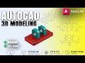
In the evolving world of mechanical engineering, the ability to transform a 2D concept into a functional 3D model is an essential skill. One of the best ways to sharpen these skills is through practical, hands-on exercises that replicate real-world components. In this guide, we explore the process of creating a mechanical mounting bracket, a fundamental tool in the world of 3D CAD.

Starting with the Foundation: The Base Plate

Every great mechanical model begins with a solid foundation. For this mounting bracket project, we start by constructing a rectangular base plate. In AutoCAD, this involves using primitive shapes or extruding a 2D rectangle to a specific thickness. By assigning a distinct color—such as a vibrant red—designers can easily differentiate between various components within a complex assembly. This level of visual clarity is one of the many advantages of using professional 3D CAD software for mechanical practice.

Precision Engineering and Mounting Holes

A mounting bracket is only as functional as its connectivity. The next critical step in the modeling process is the addition of four precise mounting holes located at the corners of the base. This requires careful measurement and the use of the "Subtract" command to create clean, accurate voids. This stage of the project emphasizes the importance of geometric constraints and precision, ensuring that the digital part would theoretically fit perfectly into a real-world mechanical assembly.

Why Practice Work is Essential

Whether you are a student or an aspiring engineer, consistent practice is the key to proficiency. Transitioning from basic shapes to complex mechanical parts helps users understand the workspace, the Z-axis, and the various shortcuts that speed up the design process. Utilizing 3D CAD for these practice sessions allows you to experiment with different materials, lighting, and viewing angles before moving on to more intricate industrial designs.

Conclusion

Modeling a mechanical mounting bracket is more than just a basic exercise; it is a stepping stone to mastering industrial design. By following these fundamental principles in AutoCAD, you can build a strong portfolio of mechanical parts and gain the confidence needed to tackle large-scale engineering projects. Keep practicing, keep designing, and unlock the full potential of your technical creativity!

Continue Reading | ความคิดเห็น

Mastering 3D CAD: How to Eliminate Tolerances Between Your Design and the Final Print

Wednesday, September 9, 2026

In the world of professional engineering and product design, precision is not just a goal—it is a requirement. However, many designers face a common frustration: a model that looks perfect in its 3D CAD environment often encounters significant dimensional errors once it passes through a slicer and reaches the 3D printer. Bridging this gap between the digital "ideal" and the physical "reality" is the key to professional-grade manufacturing.

The Digital Discrepancy: Why CAD and Slicers Conflict

The journey from a 3D CAD file to a physical object involves several layers of translation. While your design software works with precise mathematical curves and coordinates, a slicer must convert that data into a mesh (usually STL) and then into G-code toolpaths. During this conversion, small rounding errors, mesh density issues, and material shrinkage factors can lead to "tolerances" that ruin a press-fit part or a mechanical assembly.

To solve these discrepancies, professionals must look beyond the default settings. Understanding how your slicer interprets the wall thickness and hole diameters defined in your original design is the first step toward calibration.

Optimizing Your Workflow for Professional Projects

To ensure your project maintains its integrity, you must account for "Horizontal Expansion" and "Hole Expansion" within your slicing software. These settings allow you to compensate for the natural outward flow of plastic. However, the most effective way to minimize error is to design with the manufacturing process in mind. By applying a global tolerance standard (such as 0.1mm to 0.2mm) directly within your 3D CAD workspace, you create a buffer that accommodates the physical limitations of FDM or resin printing.

Scaling Up with Professional Services

Sometimes, high-stakes professional projects require more precision than a desktop setup can provide. This is where professional fabrication services like PCBWay become invaluable. Whether you are integrating a custom PCB into a 3D-printed enclosure or requiring industrial-grade SLS printing, outsourcing to a specialized facility ensures that the tight tolerances you’ve calculated in your design are mirrored in the final product.

Conclusion

Solving the variance between design and production is what separates hobbyist prints from professional prototypes. By mastering your 3D CAD tools and understanding the logic of your slicing software, you can significantly reduce waste and ensure that every part fits perfectly the first time. Precision begins at the design stage—make sure your workflow is ready for the challenge.

Continue Reading | ความคิดเห็น

Precision Design: How to Clean Up Extra Lines in AutoCAD and 3D CAD Projects

Friday, September 4, 2026

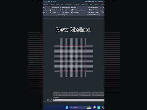
Precision is the name of the game when it comes to technical drafting. Whether you are working on a simple 2D floor plan or a complex 3D CAD model, stray lines can clutter your workspace and lead to costly errors. Learning how to efficiently remove these unwanted elements is a fundamental skill that separates amateur hobbyists from professional designers.

Why Line Management Matters

Keeping your drawing "clean" isn't just about aesthetics; it is about data integrity. In the world of professional engineering, extra lines can interfere with object snapping, bloat your file sizes, and cause significant confusion during the rendering phase. If you plan to export your 2D geometry into a more robust 3D CAD environment for extrusion or assembly, those tiny overlapping lines can prevent surfaces from closing properly, resulting in broken geometry that is difficult to fix later.

Essential Commands: Erase and Trim

The most straightforward way to remove an object is the ERASE command (shortcut: E). Simply select the line and hit enter. However, you often don't want to delete an entire entity, but rather a segment that extends too far beyond an intersection. This is where the TRIM command (shortcut: TR) becomes your most valuable tool.

In modern versions of AutoCAD, the Trim tool features a "Quick Mode" by default. This allows you to simply click or "fence" across any line segment to remove it instantly without needing to manually select cutting edges first. For those working on intricate 3D CAD layouts, holding the Shift key while using the Trim command allows you to instantly toggle to the EXTEND command, making it a versatile workflow for cleaning up messy intersections on the fly.

Using the Overkill Command for a Perfect Finish

Sometimes, extra lines aren't visible because they are hidden directly on top of each other. These "duplicate" lines are a common headache in drafting. To solve this, use the OVERKILL command. This powerful tool searches your entire workspace and automatically deletes overlapping or redundant geometry.

By mastering these simple deletion and trimming techniques, you ensure that your projects remain lightweight, professional, and ready for any advanced design stage. Whether you are a student or a seasoned pro, a clean drawing is the foundation of a successful project.

Continue Reading | ความคิดเห็น

2D to 3D Made Easy: Mastering the AutoCAD PRESSPULL Command for 3D CAD

In the fast-paced world of digital design, the ability to transition quickly from a flat sketch to a complex model is a vital skill. If you are looking to excel in 3D CAD, understanding the tools that bridge the gap between 2D drafting and 3D visualization is essential. One of the most powerful and time-saving features available to designers today is the AutoCAD PRESSPULL command.

What Makes PRESSPULL So Powerful?

While many beginners rely solely on the "Extrude" command, the PRESSPULL tool offers a much more dynamic and versatile approach. It allows you to select a bounded area—even if it is not a closed polyline—and instantly pull it into the third dimension. This versatility makes it a cornerstone for anyone looking to streamline their workflow in 3D CAD.

Beyond just adding volume, PRESSPULL is dual-purpose. It can be used to subtract material by pushing a shape into an existing solid, making it an incredibly efficient tool for creating holes, slots, or recessed features without needing complex Boolean operations.

Step-by-Step: From 2D to 3D in Seconds

Mastering this command is straightforward. Follow these steps to speed up your modeling process: 1. Initialize the Command: Type PRESSPULL in the command line or select the icon from the Modeling tab. 2. Select the Area: Hover your cursor over the 2D shape or a bounded internal area. AutoCAD will automatically highlight the detected space. 3. Define the Height: Click and drag your mouse upward to add height, or move it inward to cut through a solid. 4. Precision Entry: For exact engineering specifications, simply type in the desired numerical value and hit Enter.

Why It Changes Your Workflow

Efficiency is the ultimate goal when working on complex 3D CAD projects. The PRESSPULL command eliminates the tedious step of joining individual lines into regions or polylines before they can be transformed. It intelligently recognizes internal boundaries, allowing you to create architectural walls with window cutouts or mechanical parts with pre-drilled holes in just a few clicks.

By incorporating this simple shortcut into your daily routine, you can significantly reduce your modeling time and focus more on the creative aspects of your design. Whether you are a beginner or a seasoned professional, the PRESSPULL command is a must-know feature that makes 3D modeling feel like second nature.

Continue Reading | ความคิดเห็น

Master SolidWorks: Essential 3D CAD Modeling Tips for Beginners and Pros

Monday, August 31, 2026

SolidWorks remains one of the most powerful and widely used tools in modern engineering and product design. Whether you are an aspiring maker or an experienced mechanical engineer, mastering 3D CAD software is essential for bringing creative concepts into precise, functional models. From basic geometric sketches to complex parametric assemblies, honing your workflow saves valuable development time while boosting overall project accuracy.

Key SolidWorks Techniques for Speed and Precision

Creating clean, scalable models requires more than just knowing where tools are located—it requires a strong understanding of design intent. Here are fundamental practices to streamline your drafting process:

  • Fully Define Your Sketches: Always ensure your 2D profiles are fully constrained using smart dimensions and geometric relations (such as concentric, parallel, or equal). This prevents accidental shifts later in the design tree.
  • Maintain an Organized Feature Tree: Keep your feature manager organized. Rename key features, group related operations, and avoid unnecessary extrusions or cuts to make future edits hassle-free.
  • Leverage Shortcuts and Hotkeys: Customizing mouse gestures and keyboard shortcuts for frequently used tools like Extrude, Revolve, and Smart Dimension will dramatically speed up your execution.

Elevating Your Projects with Modern 3D CAD Workflows

As you advance beyond basic shapes, adopting structured 3D CAD workflows will significantly improve the quality of your output. Utilizing tools such as global variables and equations allows your models to adapt dynamically whenever specifications change. Furthermore, paying attention to surface fillets and visual materials helps convert basic technical parts into realistic visual assets suitable for presentations.

Consistently practicing these tips ensures your designs are not only visually impressive but also optimized for prototyping, 3D printing, and manufacturing. Investing time in mastering modern 3D CAD capabilities is the best way to sharpen your skills and stand out in the competitive design industry.

3D CAD
Continue Reading | ความคิดเห็น

Mastering SolidWorks: Smart Tips and Tricks to Accelerate Your 3D CAD Workflow

Sunday, August 30, 2026

In the world of modern engineering and product design, SolidWorks stands out as one of the most powerful software suites available. Whether you are a beginner learning the ropes or an experienced professional, streamlining your design process is key to delivering high-quality models in less time. Mastering 3D CAD software requires more than just knowing the basic commands—it is about leveraging hidden shortcuts, smart features, and workflow optimizations.

Streamline Design with Mouse Gestures and Custom Shortcuts

One of the fastest ways to boost your modeling speed in SolidWorks is by customizing your workspace. Instead of manually navigating through menus to select sketch tools, utilize mouse gestures. By enabling 8 or 12-gesture wheels, you can instantly access frequently used commands like smart dimension, extrude, or rectangle with a quick drag of the mouse. Combining mouse gestures with customized keyboard shortcuts allows you to maintain focus on the graphics area, drastically cutting down on unnecessary clicks.

Optimize Complex Assemblies for Better Performance

As your models grow in complexity, large assemblies can slow down performance and impact productivity. To maintain smooth viewport navigation, take advantage of SolidWorks’ Lightweight Mode and Defeature tools. Loading components as lightweight reduces memory usage by only retrieving model geometry when needed. Furthermore, organizing your FeatureManager Design Tree into sub-assemblies and using freeze bars prevents constant rebuilding, ensuring your 3D CAD environment remains responsive even when handling intricate multi-part projects.

Harness the Power of Smart Dimensioning and Equations

Precision is paramount in parametric modeling. Instead of manually updating dimensions across multiple parts, leverage global variables and equations. By linking critical dimensions together, modifying a single parameter automatically updates your entire model hierarchy. Additionally, using the Instant3D feature lets you drag handles to modify geometry dynamically, giving you real-time visual feedback without opening individual feature dialogs.

Conclusion

Improving your proficiency in 3D CAD design is an ongoing journey. By incorporating these practical SolidWorks tips and tricks into your daily routine, you can eliminate repetitive tasks, improve model accuracy, and significantly shorten project timelines. Start integrating these strategies today and take your 3D modeling skills to the next level!

3D CAD
Continue Reading | ความคิดเห็น

The Ultimate Guide to 3D CAD for Precision CNC Manufacturing

Sunday, August 23, 2026

In the fast-paced world of modern manufacturing, turning a rough concept into a high-precision physical component requires the right digital tools. Whether you are an experienced engineer, a machinist, or an enthusiastic hobbyist, mastering 3D CAD is the fundamental first step toward successful Computer Numerical Control (CNC) production.

From Digital Design to Physical Parts

Traditionally, manufacturing relied heavily on two-dimensional paper drawings, leaving plenty of room for interpretation and costly manual errors. Today, digital modeling software allows designers to construct virtual three-dimensional objects with microscopic precision.

These digital models serve as the master blueprint for modern machine tools. By converting solid geometries into machine-readable language (G-code), 3D CAD bridges the gap between creative design concepts and accurate physical manufacturing, ensuring every cut, drill, and pocket is executed perfectly.

Key Benefits of 3D CAD in Modern CNC Workflows

Integrating 3D modeling software into your manufacturing process offers several game-changing advantages:

  • Enhanced Visualization: Examine parts from every angle, inspect internal features, and verify proper fit within larger assemblies before cutting expensive raw material.
  • Reduced Material Waste: Simulate tool movements virtually to detect potential collisions, thin walls, or unreachable geometry early in the design stage.
  • Seamless CAM Integration: Effortlessly transfer your models directly into Computer-Aided Manufacturing (CAM) software to generate optimized toolpaths.

Tips for Creating Machine-Ready Designs

To ensure your digital drawings translate smoothly to the workshop floor, keep a few fundamental design rules in mind:

  1. Design for Tool Geometry: Standard CNC end mills are cylindrical. Always include internal radii on inside corners to accommodate round cutting tools.
  2. Maintain Reasonable Tolerances: Avoid over-specifying tight tolerances, as this significantly increases machining time and tool wear. Apply tight limits only where functional fit is critical.
  3. Optimize Wall Thickness: Keep structural integrity in mind. Extremely thin walls can vibrate or distort during the machining process under heavy cutting forces.

By incorporating robust 3D CAD practices into your product design workflow, you ensure higher manufacturing quality, faster project turnaround times, and lower overall production costs. Embrace modern digital modeling today to take your CNC projects to the next level!

3D CAD
Continue Reading | ความคิดเห็น

Download Cable Drag Chain Link 10x15mm – Free 3D Model for SolidWorks and CAD Users

Tuesday, November 11, 2025


Free 3D Model: Cable Drag Chain Link 10x15mm

If you are looking for a high-quality 3D model of a cable drag chain, this design is perfect for your engineering or automation project. The Cable Drag Chain Link 10x15mm model is now available for free download from GrabCAD.

About the Model

This 3D model represents a standard cable drag chain used to protect and guide cables in CNC machines, robots, and automation systems. The dimensions are 10x15mm, suitable for compact setups that require neat cable management.

File Information

  • Model Name: Cable Drag Chain Link 10x15mm
  • File Type: SolidWorks, STEP, and IGES
  • Category: Mechanical Components / Machine Parts
  • Source: GrabCAD Library

How to Use

Simply download the model and open it in your preferred CAD software such as SolidWorks, AutoCAD, or Fusion 360. You can modify dimensions, export formats, and integrate it into your machine design project.

Why Choose This Model

This free cable drag chain 3D model is lightweight, easy to modify, and ideal for learning or professional mechanical design. It's fully parametric and can be adapted for different cable routing applications.

Download Link

➡ Click here to download Cable Drag Chain Link 10x15mm from GrabCAD

Keywords

3D model, Cable drag chain, SolidWorks model, CAD download, GrabCAD free model, cable chain link, mechanical parts, engineering design, automation chain


Continue Reading | ความคิดเห็น

Download Free 1970 VW Beetle 3D Model – Classic Car for SolidWorks, STEP, and STL

Absolutely, here's the 3D render of the 1970 VW Beetle for product showcase:
Continue Reading | ความคิดเห็น

Popular Posts Today

 
Support : 3Dcadbrowser | Grabcad | 3Dcontentcentral | D | E | F | G
Copyright © 2028. Engineering 3DCad Appication - All Rights Reserved