Cad 3D Category

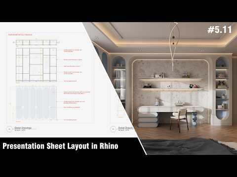
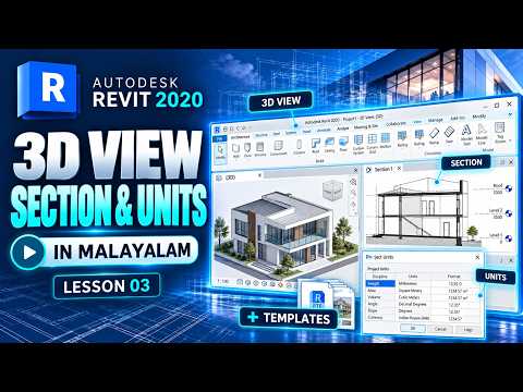
Mastering Architectural Visualizations: How to Create Exploded Isometric Views in ArchiCAD 3D

Monday, September 21, 2026

In the competitive world of architectural design, the ability to communicate complex spatial ideas clearly is what sets a professional apart. While standard floor plans and sections provide essential technical data, they often fail to capture the structural "story" of a building. This is where exploded isometric axonometries become an invaluable tool for any architect or designer.

By breaking down a project into its constituent layers—showing how the foundation, walls, and roof assemblies interact—you provide a depth of understanding that a single 3D render cannot achieve. In this guide, we explore how you can leverage the power of ArchiCAD 3D to create these stunning visual representations for your next project.

Why Use Exploded Axonometries?

An exploded view is essentially a technical "dissection" of your project. It allows clients and collaborators to see the vertical relationship between different floors and structural systems simultaneously. Using an exploded format helps highlight specific details, such as interior circulation or material transitions, without losing the context of the entire building.

Step-by-Step: Creating Your Exploded View

The beauty of working with ArchiCAD 3D is that you don't have to dismantle your actual BIM model to create these views. Instead, you can utilize the "3D Document" feature and the "Layers" system to organize your elements.

  1. Isolate Your Elements: Use the Marquee tool or Layer Combinations to select the specific parts of the building you want to display.
  2. Adjust the 3D Projection: Set your view to an Isometric Axonometry. This ensures that all parallel lines remain parallel, which is the hallmark of a professional architectural diagram.
  3. The "Lifting" Process: Instead of moving the actual model components (which would ruin your floor plans), many experts recommend using the "3D Document" settings to offset the visual representation of certain levels or using the "3D Styles" to distinguish between structural layers.
  4. Refine the Aesthetics: Once your exploded view is positioned, adjust your shadows and contours to give the drawing a clean, crisp look.

Enhancing Professionalism with ArchiCAD 3D

One of the most significant advantages of using ArchiCAD 3D for these diagrams is the synchronization between your model and your visuals. If you change a wall thickness or a window position in your floor plan, your exploded isometric view can be updated automatically. This ensures that your artistic presentations remain 100% accurate to your technical documentation.

By mastering this technique, you can transform a standard presentation into an immersive visual experience that clearly demonstrates your design intent and technical expertise.

Continue Reading | ความคิดเห็น

How to Create Western 3D Text in Cinema 4D 3D Using the Reeper X Plugin

Looking to add a rugged, classic wild-west aesthetic to your motion graphics portfolio? Designing custom typography with a vintage Western vibe is a fantastic way to sharpen your modeling skills. If you want to add a rustic, vintage flair to your motion graphics, mastering Cinema 4D 3D typography is a game-changer.

In this guide, we will explore how to craft striking Western-style lettering using Cinema 4D alongside a powerful, free rope generator plugin called Reeper X.

What is the Reeper X Plugin?

Creating realistic ropes, threads, or stitched borders around complex text paths manually can take hours. Reeper X is a popular C4D plugin specifically designed to generate ropes along splines effortlessly. By wrapping stitched rope details around heavy slab-serif lettering, you can achieve that authentic, hand-crafted Western look in minutes. It works seamlessly across various versions of Cinema 4D, making it an essential free tool for any 3D designer's toolkit.

Step-by-Step: Building Your Western 3D Text

Creating a detailed Western font layout requires the right tools, and in Cinema 4D 3D, free plugins can significantly speed up your workflow. Here is how to construct the effect from scratch:

  1. Set Up the Base Typography: Start by creating a MoText object. Choose a heavy, slab-serif font (such as Rosewood or Western) to capture the traditional frontier look. Give your text a generous extrude depth to provide a solid structure.
  2. Apply Bevels and Insets: Adjust the cap settings to create distinct front bevels. Western typography relies heavily on layered contours and framed edges.
  3. Generate the Rope Border with Reeper X: Extract the spline outline from your text caps. Apply the Reeper X plugin to this spline to automatically generate twisted strands of rope framing your text. Adjust the coil count, thickness, and rotation within the plugin settings until it hugs the text outline perfectly.
  4. Texturing and Lighting: Apply warm wood textures or worn leather materials to the main text body. Give the Reeper X rope elements a coarse fiber texture. Set up a three-point lighting rig with warm key lights and cool rim lights to emphasize the tactile depth of the ropes and bevels.

Final Thoughts

Combining standard modeling tools with creative third-party plugins opens up endless artistic possibilities. With a bit of practice, you can elevate your Cinema 4D 3D text designs and bring an iconic retro aesthetic to life in your next video project. Download Reeper X, experiment with different spline paths, and give your typography project a real Western standoff visual!

Continue Reading | ความคิดเห็น

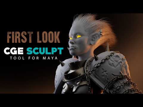
Unleashing Creativity with ZBrush 3D: A Showcase of My Latest Sculpts and Tips

Are you ready to dive into the mesmerizing world of digital sculpting? Whether you are a seasoned character designer or just beginning your journey in digital art, working with ZBrush 3D offers an unparalleled creative experience. Today, I am excited to share a showcase of my latest sculpts, along with a few essential tips to help you level up your digital sculpting workflow.

Bringing Characters to Life with ZBrush 3D

Creating detailed 3D models requires both artistic patience and the right set of tools. Over the past few months, I’ve been experimenting with dynamic forms, intricate textures, and detailed hard-surface elements. ZBrush 3D remains the industry-standard software for digital sculpting, allowing artists to translate raw imagination into high-poly, production-ready assets.

In my latest video, I walk you through several of my recent sculpted pieces. From initial block-outs using basic primitives to refining fine pore details and anatomical structures, each model represents a unique set of challenges and learning moments. Observing how light hits sculpted surfaces can dramatically change the impact of your artwork, making solid form and proportion crucial right from step one.

Quick Tips for a Better Sculpting Workflow

If you want to enhance your sculpting speed and quality, keep these core practices in mind:

  • Master the Blocking Phase: Never rush into high-subdivision details before your base mesh proportions are rock solid.
  • Leverage Custom Brushes: Build or collect custom brushes for repeated details like skin textures, fabric seams, and hair strands.
  • Utilize Dynamic Topology: Keep your topology flexible early in the process so you can sculpt freely without worrying about polygon distribution.

Join the Community and Support the Channel

Building a strong artistic foundation takes practice, but sharing the journey makes it far more rewarding. If you enjoyed taking a peek at these sculpts and found the insights helpful, be sure to like the video and subscribe to the channel for more tips and tricks. Also, don't forget to check out our brand-new Inglorious Merch line to gear up and support our growing creative community!

Continue Reading | ความคิดเห็น

Mastering the Blade: My Journey Modeling Roronoa Zoro’s Katanas in Blender 3D

Sunday, September 20, 2026

For any fan of One Piece, Roronoa Zoro isn’t just a character; he is a symbol of discipline, strength, and the legendary Santoryu (Three-Sword Style). As a 3D artist, there is no greater challenge than taking these iconic weapons—Wado Ichimonji, Sandai Kitetsu, and Enma—and bringing them to life in a digital space. Recently, I embarked on a personal marathon to recreate all of Zoro's swords to test my technical limits and refine my workflow.

The Challenge of the Three-Sword Style

Modeling a katana might seem simple at first glance, but the complexity lies in the details. Each of Zoro's blades carries a distinct personality. From the elegant, minimalist design of the Wado Ichimonji to the flame-like hamon patterns on Shusui, every element requires precision. This project wasn't just about making "cool swords"; it was about practicing hard-surface modeling, understanding curves, and mastering the art of the tsuba (handguard) design.

Why Blender 3D was the Perfect Tool

To achieve the level of detail necessary for these legendary blades, I relied heavily on Blender 3D. The software’s versatility allowed me to switch seamlessly between poly-modeling the blade's edge and sculpting the intricate wraps on the hilt. Using Blender 3D, I was able to experiment with different modifiers to ensure the curvature of the blades remained consistent and realistic, mimicking the traditional forging process of a real katana.

Bringing the Steel to Life

The real magic happened during the texturing and shading phase. A sword is only as good as its steel, and capturing the reflective properties of high-carbon metal was a lesson in material nodes. I focused on creating custom shaders that highlighted the unique temper lines of each blade. By utilizing the Eevee and Cycles engines within Blender 3D, I could visualize how light would dance off the edge of the Santoryu blades, giving them a cinematic feel that does justice to the source material.

Final Reflections

This project was more than just a fan-art tribute; it was a deep dive into the "true learning" of 3D art. It taught me that growth happens when you stop following tutorials step-by-step and start applying those techniques to a subject you are passionate about. Whether you are a beginner or a seasoned artist, pushing your boundaries with a complex project like this is the fastest way to sharpen your skills.

Stay tuned as I continue to explore the intersection of anime and digital art, one vertex at a time!

Continue Reading | ความคิดเห็น

Master Architectural Site Analysis: Integrating Google Earth with SketchUp 3D

For architects and urban planners, context is everything. While many professionals view Google Earth simply as a quick way to inspect satellite imagery, it is actually a robust, data-rich platform capable of transforming your early-stage architectural workflow. From conducting thorough site analyses to extracting accurate terrain and elevation data, Google Earth provides invaluable insights long before you break ground or open your design software.

Analyzing Site Terrain and Elevation Profiles

A successful design starts with understanding the unique characteristics of the land. Google Earth allows designers to evaluate slope, contour variations, and elevation profiles effortlessly. By studying the surrounding topography, sun patterns, and adjacent built environments, architects can make informed decisions regarding building placement, orientation, and grading. This preliminary site analysis saves significant time and helps prevent costly structural revisions during later design stages.

Seamlessly Integrating Context into Your Modeling Workflow

One of the greatest advantages of leveraging Google Earth in modern architecture is its compatibility with advanced modeling platforms. By importing geolocated satellite imagery and terrain contours directly into SketchUp 3D, designers can establish an accurate real-world context for their building models. Generating detailed topography within your digital workspace allows you to see exactly how your structure interacts with existing slopes, adjacent streets, and neighboring buildings. This bridge between geographic data and 3D space ensures that your models reflect true environmental conditions.

Enhancing Conceptual Designs and Client Presentations

Beyond initial spatial planning, combining Google Earth’s macro-level context with SketchUp 3D precision enables compelling visual storytelling. You can simulate sun studies, analyze visual impact from surrounding viewpoints, and present a holistic vision to clients and stakeholders. Instead of viewing a project in isolation, stakeholders can appreciate how the proposed building harmonizes with the surrounding landscape.

Final Thoughts

Integrating Google Earth into your early design phase bridges the gap between raw geographic data and creative architectural vision. By combining powerful site analysis tools with software like SketchUp 3D, you elevate both the precision of your site modeling and the quality of your final design proposal. Start utilizing these integrated tools today to create smarter, context-aware architecture.

Continue Reading | ความคิดเห็น

Master SolidWorks 3D: Converting 2D Drawings into Professional 3D Models

In the world of mechanical engineering and industrial design, the ability to interpret a flat, two-dimensional blueprint and transform it into a functional digital prototype is a vital skill. Today, we are diving deep into Exercise 76 from Guru Design LAB, where we explore how to harness the power of SolidWorks 3D to create complex mechanical parts with precision and efficiency.

The Bridge Between 2D Sketches and 3D Reality

The transition from a 2D drawing to a 3D model is where the magic happens. For many beginners, looking at a technical drawing filled with dimensions, hidden lines, and center marks can be intimidating. Exercise 76 simplifies this process. By breaking down the part into its fundamental geometric shapes, you can plan your modeling strategy before you even place your first sketch relation.

In this tutorial, Guru walks you through the essential workflow of identifying the primary plane, establishing the base feature, and layered additions. Using SolidWorks 3D allows for a parametric approach, meaning any change you make to your initial 2D sketch will automatically update your final model, ensuring accuracy throughout the design cycle.

Step-by-Step Modeling Strategy

The process begins with a robust base sketch. In Exercise 76, we focus on utilizing the Extruded Boss/Base feature to give our 2D shapes volume. Key highlights of this session include:

  1. Sketching with Constraints: Learning how to use relations like "Coincident" and "Tangent" to keep your model fully defined.
  2. Feature Application: Moving beyond simple extrusions to include cuts, holes, and fillets that define the part’s mechanical utility.
  3. Refining the Geometry: Using tools like the Hole Wizard to ensure that the mechanical specifications of the part meet industry standards.

Why Structured Practice Matters

Consistency is the secret to becoming a proficient designer. By following structured tutorials like this one, you learn more than just which buttons to click; you learn the logic behind professional part design. Mastering SolidWorks 3D through these exercises ensures that you can handle real-world engineering challenges, from simple brackets to complex machinery components.

Whether you are a student looking to sharpen your skills or a professional seeking a quick refresher, Exercise 76 provides a comprehensive look at the modern CAD workflow. Remember, every complex machine started as a simple sketch—it’s time to bring your designs to life!

Continue Reading | ความคิดเห็น

Mastering Jewelry CAD: Creating a Stunning Baguette Twin Shank Ring with Rhino 3D

Jewelry design has entered a new era of precision and creativity thanks to advanced digital tools. One of the most elegant designs to master is the Baguette Twin Shank Ring—a piece that combines architectural symmetry with the timeless brilliance of step-cut diamonds. In this guide, we explore the intricate process of bringing this sophisticated vision to life through professional CAD techniques.

The Architecture of the Twin Shank

The beauty of a twin shank ring lies in its structural complexity. Unlike a traditional single band, the twin shank requires a delicate balance to ensure both bands flow harmoniously toward the center setting. The process begins with establishing the base finger rail and sweeping the profiles. Precision is key here; the gap between the shanks must be consistent to maintain the "light" and "airy" aesthetic that makes this style so popular in modern fine jewelry.

Setting Baguette Stones with Rhino 3D

Baguette diamonds demand a high level of accuracy because of their straight edges and specific geometric proportions. Using Rhino 3D, designers can meticulously align each stone within the channel or prong setting. This software allows for the exact calculation of metal thickness and stone spacing, ensuring that the final cast piece requires minimal manual cleanup. When working with twin shanks, the transition point where the stones meet the dual bands is the most critical area to refine, requiring a smooth surface flow to ensure wearer comfort.

Pro-Tips for a Flawless Workflow

To elevate your jewelry design game, focus on your Boolean operations and history-enabled modeling. By utilizing the robust toolset available in Rhino 3D, you can create parametric-like adjustments. For instance, if you decide the baguette stones need to be slightly larger or the shank needs a different taper, having a clean, organized workflow allows you to make these changes without rebuilding the entire model from scratch. Always remember to check your tolerances for 3D printing; a design that looks flawless on the screen must also be structurally sound for casting in gold or platinum.

Conclusion

The Baguette Twin Shank Ring is a testament to how modern technology meets traditional craftsmanship. Mastering this specific style will not only sharpen your technical skills but also expand your design repertoire for high-end clients. By combining artistic vision with the power of digital modeling, the possibilities for innovation are endless.

Continue Reading | ความคิดเห็น

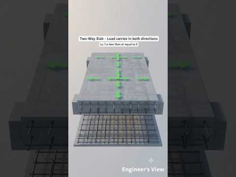
Shallow vs. Deep Foundations: A Comprehensive Guide for Civil 3D Professionals

Saturday, September 19, 2026

Every great structure starts beneath the surface. For engineers and designers working on infrastructure projects, choosing the right foundation type is the most critical decision in the early stages of design. Whether you are utilizing advanced modeling software like Civil 3D to map out site topography or managing a construction site, understanding the fundamental differences between shallow and deep foundations is essential for structural integrity.

What is a Shallow Foundation?

Shallow foundations, often referred to as spread footings or open foundations, are typically used when the soil near the surface has sufficient bearing capacity to support the structural load. These foundations are generally wider than they are deep, allowing the weight of the building to be distributed across a larger surface area.

Common types include: * Isolated Footings: Used for individual columns. * Combined Footings: Support two or more columns. * Mat or Raft Foundations: A thick slab that supports the entire structure, ideal for soil with low bearing capacity or varying loads.

Shallow foundations are preferred for smaller residential buildings and low-rise commercial structures because they are cost-effective and easier to construct.

What is a Deep Foundation?

When the surface soil is too weak, compressible, or unstable to support a building’s weight, engineers must look deeper. Deep foundations transfer the structural load to a more competent layer of soil or solid rock far below the ground level.

The most common types of deep foundations are: * Pile Foundations: Long, slender members made of steel, concrete, or wood driven into the ground. * Drilled Shafts (Caissons): Large-diameter cylinders created by removing soil and filling the void with reinforced concrete.

These are essential for skyscrapers, bridges, and structures built on expansive clay or near water bodies where soil erosion is a concern.

The Role of Technology in Foundation Selection

In modern engineering, the decision-making process is data-driven. Designers often utilize Civil 3D to analyze surface conditions, grading, and subterranean data. By creating precise digital models within Civil 3D, engineers can visualize how a foundation will interact with the surrounding terrain, ensuring that the transition from the structure to the earth is seamless and safe.

Key Differences at a Glance

  1. Depth: Shallow foundations are usually placed within a few meters of the surface, while deep foundations can reach depths of 20 to 100 meters.
  2. Cost: Shallow foundations are significantly more affordable due to less material and simpler excavation.
  3. Mechanism: Shallow foundations rely on the bearing area, whereas deep foundations rely on end-bearing (resting on rock) or skin friction (grip against the soil).

Choosing the right foundation is a balance of safety, soil mechanics, and budget. By mastering these concepts, you ensure the longevity of every project you build.

Continue Reading | ความคิดเห็น

Master Furniture Visualization: How to Model, Texture, and Light a Sofa in 3ds Max

Creating realistic 3D furniture is an essential skill for architectural visualization artists and interior designers alike. Whether you are building an arch-viz portfolio or creating high-end assets for virtual environments, mastering sofa design is a crucial milestone. In this tutorial walkthrough, we break down the complete end-to-end workflow for modeling, texturing, and lighting a stylish modern sofa using 3ds Max and V-Ray.

Step 1: Precision 3D Modeling

The foundation of any stunning 3D asset lies in clean topology and accurate proportions. Starting from simple primitive objects, we utilize advanced polygon modeling techniques in 3ds Max to block out the sofa frame, armrests, and seating cushions. To achieve photorealism, paying attention to tiny details is key—softening hard edges with chamfers, sculpting subtle organic wrinkles on the cushions, and ensuring proper real-world scale.

Step 2: Realistic Texturing with V-Ray

Once the base mesh is complete, the next step is applying believable shaders. Using V-Ray materials, you can recreate the authentic look and tactile feel of luxury fabrics, leather, or wooden legs. Proper UV unwrapping is critical here to prevent pattern stretching across curved surfaces. Utilizing diffuse, bump, and roughness maps together gives the fabric micro-details that react naturally to surroundings.

Step 3: Studio Lighting Setup

Lighting transforms a flat model into a dramatic, photorealistic image. By setting up a classic studio lighting environment with soft V-Ray lights, you can highlight the contours, fabric weaves, and subtle shadow falloffs of the furniture piece. Adjusting light temperatures and camera exposure helps capture the welcoming ambiance of a realistic living space.

Conclusion

Mastering these essential steps allows you to produce high-quality, professional furniture renders. With dedicated practice in 3ds Max, you can elevate your 3D modeling skill set and deliver incredible visuals for client projects or personal portfolios. Check out the full video tutorial to follow along with the step-by-step process!

Continue Reading | ความคิดเห็น

Mastering Digital Creation: Why Maya 3D is the Industry Standard for Artists

In the rapidly evolving world of digital media, one software package stands out as the ultimate powerhouse for professionals: Maya 3D. From blockbuster Hollywood films to top-tier AAA video games, this comprehensive suite from Autodesk has become synonymous with high-end visual effects, complex character animation, and stunning digital environments.

The Versatility of Professional Modeling

Whether you are an aspiring artist or a seasoned professional, the modeling capabilities found within this software are unparalleled. It provides a robust set of tools for polygonal, NURBS, and subdivision surface modeling. Its ability to handle intricate details while maintaining a streamlined workflow allows artists to bring even the most complex concepts to life. With features like the integrated Modeling Toolkit and advanced UV mapping, the transition from a simple primitive shape to a hyper-realistic character is smoother than ever. Using Maya 3D allows for a level of precision that is essential for modern CGI production.

Industry-Leading Animation and VFX

Beyond static models, the real magic happens when things start to move. The platform is widely regarded as the gold standard for character rigging and animation. Its sophisticated physics engines and procedural toolsets allow for the creation of breathtaking effects—from realistic water simulations to complex motion graphics. For VFX artists, the software offers a deep level of control over lighting, shading, and rendering, ensuring that every frame meets the highest cinematic standards.

Getting Started on Your Creative Journey

Learning a tool this powerful can seem daunting at first, but the rewards are well worth the effort. The community surrounding the software is vast, offering countless tutorials and resources for those looking to sharpen their skills. By mastering the fundamentals of the interface and understanding the core production pipeline, you can open doors to career opportunities in film, gaming, and architectural visualization.

If you are ready to push the boundaries of what is possible in the digital realm, embracing the tools provided by Maya 3D is the definitive first step toward becoming a world-class creator. Whether you are interested in shorts, feature films, or interactive media, the power to create is at your fingertips.

Continue Reading | ความคิดเห็น

Mastering Precision Design: How to Create a Crown Wireframe Structure in Inventor 3D

When it comes to high-level mechanical design and intricate geometric modeling, Autodesk Inventor remains a top-tier choice for engineers and designers worldwide. In this guide, we dive into Exercise 227, focusing on the creation of a sophisticated crown-shaped wireframe structure. This particular exercise is designed to test your precision and help you master complex sketching techniques within the software environment.

The Power of Wireframe Modeling

Wireframe structures are the backbone of many advanced industrial designs. Unlike solid modeling, a wireframe focuses on the skeleton of the object, defining the edges and vertices that form its volume. Creating a crown-shaped structure requires a deep understanding of 3D sketching and constraints. By using Inventor 3D, designers can create a series of interconnected paths that represent the delicate yet strong curves of a crown, ensuring that every angle is mathematically accurate.

Key Steps in the Design Process

To begin the crown wireframe, you start with a foundational 2D sketch to establish the base diameter. However, the true magic happens when you transition into the 3D sketching environment. Here, you will use splines and geometric constraints to pull the structure upward, forming the iconic peaks and valleys of a crown.

Precision is the name of the game in this exercise. Using Inventor 3D, you can leverage the "Circular Pattern" tool to ensure that the ornamental ribs of the crown are perfectly symmetrical around the center axis. This not only saves time but guarantees that the structural integrity of the design is maintained throughout the modeling process.

Refining for Professional Results

Once the basic wireframe is established, the next step involves refining the paths. In professional workflows, these wireframes often serve as the path for "Sweep" or "Pipe" commands to create physical wire components. Exercise 227 emphasizes the importance of smooth transitions between segments. By mastering these techniques, you enhance your ability to tackle complex architectural and mechanical projects that require more than just basic primitive shapes.

Whether you are a student or a seasoned professional, practicing these intricate designs in Inventor 3D is an excellent way to sharpen your spatial reasoning and technical skills. This exercise proves that even the most complex aesthetic shapes can be broken down into manageable, logical steps using the right CAD tools.

Continue Reading | ความคิดเห็น

The Future of Disaster Recovery: Why Parametric Insurance is a Game Changer

Friday, September 18, 2026

In an era of increasing climate volatility, the speed of financial recovery is often as critical as the recovery itself. Traditional reinsurance has long relied on the "indemnity" model—a process where payouts are determined by the actual physical loss incurred. While effective, this model is often plagued by lengthy damage assessments and complex claim adjustments that can delay vital funds for months.

Enter a faster, more transparent alternative. The rise of parametric insurance has shifted the landscape of disaster finance by focusing on objective triggers rather than subjective loss assessments.

How Index-Based Triggers Work

Unlike traditional policies, a parametric solution pays out based on the occurrence of a specific event that meets a predefined threshold. For example, a policy might be triggered if a hurricane reaches Category 4 status within a specific geographic coordinate, or if an earthquake exceeds a 7.0 magnitude.

Because the payout is tied to an independent data index—such as wind speed or seismic intensity—there is no need for a claims adjuster to visit the site to calculate physical damage. This "if-then" logic ensures that funds are released almost immediately after the event is verified by a third-party data source.

Bridging the Protection Gap with Cat Bonds

One of the most revolutionary applications of this technology is found in Catastrophe Bonds (Cat Bonds). These financial instruments allow insurers to transfer risk directly to capital market investors. By using these structures, organizations can secure large-scale funding that remains liquid and ready to deploy. This mechanism provides a vital safety net for governments and large enterprises, ensuring that essential services and reconstruction efforts can begin without the usual bureaucratic hurdles of traditional insurance.

The Advantage of Speed and Certainty

The primary benefit of this model is liquidity. In the wake of a natural disaster, immediate cash flow can be the difference between a quick recovery and long-term economic stagnation. By removing the uncertainty of the claims process, parametric reinsurance provides a level of financial predictability that traditional models simply cannot match. As we face a future with more frequent extreme weather events, these innovative financial tools are becoming a cornerstone of global resilience and disaster preparedness.

Continue Reading | ความคิดเห็น

Mastering Solid Modeling in CATIA V5: The Ultimate Multi-Section Solid Guide

In the world of computer-aided design (CAD), mastering advanced solid modeling techniques is essential for creating complex, organic, and aerodynamic shapes. CATIA V5 remains an industry standard for engineers and designers, offering a vast array of powerful features. Among these, the Multi-Section Solid tool stands out as one of the most versatile functions for creating intricate 3D geometry between multiple profile sections.

Whether you are designing automotive body panels, turbine blades, or consumer products, understanding how to control cross-sectional transitions is crucial for clean, manufacturable models.

Understanding the Multi-Section Solid Tool

The Multi-Section Solid tool allows designers to build a solid body by connecting two or more planar profiles along a designated path. While basic extrusions and pads handle simple prismatic shapes, advanced solid modeling requires precise control over how surfaces blend between distinct cross-sections.

To achieve predictable, smooth geometry without unwanted twists or surface tears, you must master three fundamental elements: Spines, Guides, and Coupling.

Key Components: Spines, Guides, and Coupling

  • Spines: The spine acts as the structural backbone of your multi-section feature. It controls the orientation and normal alignment of intermediate sections along the shape's length, ensuring balanced material distribution.
  • Guides: Guide curves are user-defined paths that govern the outer boundaries of the solid. They dictate how the edge profile morphs from one section to another, giving you complete engineering control over the outer contour.
  • Coupling: Coupling establishes how points on one profile connect to corresponding points on the next profile. Proper coupling prevents surface distortion, self-intersection, and topological errors.

Best Practices for Error-Free Geometry

To achieve consistent success in your solid modeling projects within CATIA V5, keep these practical tips in mind:

  1. Align Closing Points: Always verify that the closing point vectors on all selected profiles point in the same relative direction. Opposite directions will cause the feature to twist or fail entirely.
  2. Maintain Vertex Consistency: Whenever possible, create profiles with an equal number of vertices. This simplifies point coupling and ensures cleaner geometry.
  3. Ensure Smooth Guide Curves: Make sure your guide curves maintain tangency and continuity to prevent sharp breaks or surface errors on the final model.

Conclusion

Mastering the Multi-Section Solid tool is a key milestone for any CAD designer. By understanding how to combine spines, guides, and coupling options effectively, you can tackle complex design challenges and produce professional-grade 3D models with confidence.

Continue Reading | ความคิดเห็น

Beyond Organization: Unlock the True Power of Layers in CAD Software

When designing complex technical drawings, using modern CAD software is essential for precision and speed. However, many engineers and designers only use CAD layers as digital file folders to keep line work tidy. While organization is a major benefit, layers offer far more value than simple categorization.

If you want to optimize your workflow, improve design accuracy, and save hours of editing time, understanding the full potential of CAD layers is crucial. Here is why layers are the true backbone of efficient engineering design.

Effortless Editing of Complex Drawings

As technical drawings grow in detail, modifying specific components becomes increasingly difficult. Without proper layering, selecting a single line can accidentally alter surrounding elements. By assigning different components—such as dimensions, annotations, structural framing, or electrical wiring—to distinct layers, you can lock, freeze, or hide non-relevant details. This allows you to edit precise sections safely and rapidly without visual clutter getting in your way.

Streamlined Review and Collaboration

In collaborative engineering projects, multiple stakeholders need to review different aspects of the same design. Architects may focus on spatial layouts, while structural engineers focus on load-bearing components. Utilizing layer controls within your CAD software allows you to customize views for different audiences in seconds. Instead of creating separate drawing files for each discipline, you can simply toggle layer visibility on or off, ensuring every team member reviews only the information relevant to them.

Enhanced Drawing Management and Standardized Output

Layers do more than manage visibility; they also control line weights, colors, linetypes, and plot settings. Setting up standard layer properties ensures that your final prints and PDF exports maintain a uniform visual hierarchy across all project sheets. Furthermore, turning off complex, unneeded layers while actively drafting significantly improves software performance, reducing display lag on large-scale blueprints.

Conclusion

CAD layers are much more than a neat filing system—they are a powerful tool for control, performance, and seamless communication. Ultimately, mastering layer management is one of the easiest ways to level up your drafting efficiency and maximize the value of your CAD software. Rethink your layer strategy today, and watch your design workflow become faster, cleaner, and far more professional.

Continue Reading | ความคิดเห็น

Streamline Your Design Workflow: How to Review 3D CAD Models Without Screenshots

If you work in engineering, manufacturing, or product design, you know the struggle of reviewing complex digital models. The traditional feedback loop is notoriously clunky: capture a static screenshot, draw red arrows, write a lengthy email explanation, and hope the designer understands exactly which component you are referencing.

This outdated process wastes valuable time and frequently leads to miscommunication. Fortunately, there is a far better way to collaborate on 3D CAD projects without relying on 2D screenshots ever again.

The Flaws of Screenshot-Based Feedback

Taking screenshots to mark up design changes creates a massive disconnect. A static image strips away the interactive nature of a three-dimensional model. When reviewing intricate 3D CAD assemblies, a single image rarely captures the full context of a part, its clearance, or its relationship to surrounding components.

Furthermore, managing dozens of image files across disparate email chains or chat threads makes tracking revision history a nightmare. Important feedback inevitably gets buried, leading to costly errors down the line.

Pin Feedback Directly with CAD ROOMS

Imagine being able to drop a pin right onto a specific face, edge, or component of a live model and leave your comments directly where the issue exists. That is precisely what CAD ROOMS enables you to do.

By moving away from static captures and adopting direct 3D annotation, teams can revolutionize their design walkthroughs:

  • Contextual Clarity: Feedback is attached directly to the precise geometric feature in question, eliminating any ambiguity.
  • Interactive Exploration: Reviewers can rotate, zoom, and section the model while reading feedback to fully understand the suggested modification.
  • Centralized Communication: All notes, questions, and approvals stay embedded within the project environment, serving as a single source of truth for the entire team.

Elevate Your Design Collaboration

Upgrading your review pipeline dramatically transforms team productivity. Whether you are conducting an internal design review or presenting proposals to external stakeholders, commenting directly within the project environment shortens revision cycles and keeps projects moving forward.

It is time to ditch the endless screenshot folders and modernize your feedback loop. By leveraging tools built for interactive annotation, managing your 3D CAD review process becomes seamless, clear, and efficient.

Continue Reading | ความคิดเห็น

Can CAD Explain Offside? How DraftSight Reveals the Geometry of Football

Thursday, September 17, 2026

The offside rule in football has sparked endless debates among fans, players, and pundits for generations. With the introduction of modern Video Assistant Referee (VAR) technology, millimeter-precision lines are drawn on-screen to determine whether an attacker holds an unfair advantage. But how do these visual lines actually work geometrically? As it turns out, powerful computer-aided design software can easily demystify the science behind the pitch.

Understanding Offside Lines Through 2D CAD

When viewing a football match through a broadcast camera, perspective distortion can make a parallel line look angled. Determining whether a player is offside requires converting a tilted camera view into a mathematically accurate grid. By leveraging DraftSight, a leading 2D CAD software solution, analysts can project exact reference lines aligned with the pitch boundaries and vanishing points. This geometric approach ensures that camera angles do not trick the human eye.

How DraftSight Transforms Spatial Analysis

Using precise drafting tools, DraftSight enables users to plot accurate reference points, overlay vector lines on freeze-frame footage, and measure distances with complete precision. Beyond analyzing controversial sports moments, this level of geometric accuracy demonstrates the incredible versatility of 2D drafting tools. Whether you are mapping out complex architectural blueprints or calculating precise spatial relationships on a sports field, professional CAD software provides the accuracy needed to make definitive calls.

The Intersection of Sports and Engineering

The relationship between engineering software and sports analytics is growing rapidly. Tools like DraftSight showcase how fundamental CAD principles extend far beyond traditional design offices, offering clarity where human observation falls short. The next time you watch a tight offside call on matchday, remember that geometry and CAD drafting are working behind the scenes to bring absolute precision to the game.

Continue Reading | ความคิดเห็น

Blender Noob vs PRO: Level Up Your 3D Geometry with Bridge Secrets

Connecting faces or filling gaps in Blender is one of the most common tasks every 3D artist encounters. While beginners often resort to tedious, manual face creation, professionals use fast and efficient workflow tricks. Mastering tools like Bridge Edge Loops allows you to clean up complex 3D geometry in seconds rather than minutes.

Whether you are building hard-surface assets or organic character models, learning how to bridge faces efficiently will transform your workflow from a Blender beginner into a seasoned pro.

The Beginner Trap vs. The Pro Approach

When starting out, most beginners select individual edges and press the F key repeatedly to build face by face. While this method works for simple flat shapes, it quickly becomes a nightmare when working with curved surfaces, hollow structures, or intricate meshes.

PRO artists, on the other hand, rely on the Bridge Edge Loops feature. By simply selecting two opposite edge loops or face regions and calling the tool, Blender automatically generates clean connecting quads between the selection. This single shortcut dramatically reduces modeling time and prevents topological errors.

Unlocking Secret Bridge Options

The real magic happens right after you execute the bridge tool. By opening the Operator Panel in the bottom-left corner of the viewport, you unlock several hidden controls:

  • Number of Cuts: Instead of a flat bridge, increase the cut count to add automatic subdivisions across the newly created section.
  • Interpolation & Profile Factor: Adjust these parameters to turn straight bridges into smoothly curved arches, pipes, or organic forms without manual sculpting.
  • Twist Offset: If your generated faces look crossed or inverted, adjusting the twist offset instantly fixes misaligned 3D geometry.

Elevate Your Modeling Workflow

Understanding how to manipulate and connect mesh elements efficiently is fundamental to high-level 3D design. By moving away from manual face creation and leveraging Blender's powerful bridging capabilities, you ensure clean, subdivision-ready 3D geometry that renders beautifully and remains easy to edit.

Give these quick bridge secrets a try in your next Blender project, and watch your 3D modeling speed double instantly!

Continue Reading | ความคิดเห็น

Mastering AutoCAD: A Beginner’s Guide to Essential CAD tools and Commands

Have you ever looked at a complex architectural blueprint and wondered how such precision is achieved? AutoCAD is the industry-leading software for 2D and 3D design, serving as the backbone for architects, engineers, and designers worldwide. However, for a complete beginner, the interface can often feel overwhelming. The key to success lies in mastering the fundamental CAD tools that form the basis of every professional drawing.

Getting Started with the AutoCAD Interface

Before diving into complex designs, it is crucial to understand that AutoCAD is a command-driven environment. While you can click icons, the most efficient way to work is by using keyboard shortcuts. This approach not only speeds up your workflow but also allows you to focus more on the creative aspect of your project. As you familiarize yourself with the workspace, you will notice that most high-level drafting relies on a handful of core functions.

Essential Drawing Commands

To start your journey, you must master the basic drawing commands. The "Line" (L) command is perhaps the most used feature, allowing you to create straight segments between two points. Similarly, the "Circle" (C) and "Rectangle" (REC) commands allow for the quick generation of geometric shapes. By learning how to input specific coordinates and dimensions into these CAD tools, you ensure that your designs are accurate to the millimeter.

Modifying and Refining Your Designs

Drawing a line is only the beginning; the real power of AutoCAD lies in its modification capabilities. Tools such as "Trim" (TR) allow you to cut overlapping lines, while "Offset" (O) is indispensable for creating parallel lines—perfect for defining wall thicknesses in floor plans. Additionally, the "Mirror" (MI) command can save hours of work by reflecting symmetrical objects across an axis.

Conclusion: Practice Makes Perfect

Mastering AutoCAD is a journey of consistency. By focusing on these primary CAD tools and practicing them daily, you will transform from a novice into a confident drafter. Remember, every complex architectural marvel started with a simple line. Start small, stay curious, and keep practicing your commands to unlock the full potential of digital drafting.

Continue Reading | ความคิดเห็น

Master the Art of Flawless Rendering: How to Achieve Perfectly Flat Walls

Achieving a smooth, professional finish on brickwork is the hallmark of a skilled tradesperson. While many beginners focus solely on the consistency of the mortar mix, the secret to a truly flat surface lies in the tools and the technique used during the leveling phase. If you want to master the art of rendering, understanding the mechanics of the plastering rule is essential.

The Role of the Plastering Rule

A plastering rule, also known as a straight edge or screed, is more than just a piece of metal; it is a precision instrument. Its primary function is to act as a guide that spans across the uneven surface of the wall. When you apply your base coat of mortar, the thickness is rarely uniform. By using a rigid straight edge, you create a mechanical reference point that bridges the "peaks" and "valleys" of the wet material, allowing you to see exactly where the wall needs adjustment.

Technique: Pulling and Leveling

The magic happens in the movement. The rigid straight edge acts like a precision guide as you work. As you pull the rule upward across the wet mortar, the sharp, rigid edge shears off excess material. This action does two things simultaneously: it flattens the high points and reveals where more mortar is needed.

For those serious about high-quality rendering, this step cannot be rushed. You must maintain consistent pressure and a steady angle to ensure the rule doesn’t "dig in" or skip over the surface. The goal is to let the tool do the heavy lifting of identifying imperfections that the human eye might miss.

Achieving the Perfectly Flat Result

Once the excess is removed, you can use that same material to fill in any voids or hollows identified by the straight edge. This cycle of screeding and filling continues until the rule glides across the wall without leaving gaps behind it. This process ensures that your final surface is not just smooth to the touch, but geometrically flat.

Mastering these fundamentals will significantly improve the durability and aesthetic of your masonry work. By treating your straight edge as a precision guide, you ensure that your rendering projects stand the test of time and look flawless under any lighting conditions. Whether you are a DIY enthusiast or a professional looking to sharpen your skills, the key to success is patience and the right tool for the job.

Continue Reading | ความคิดเห็น

Next-Gen Engineering: Top 5 GitHub Repositories for CAD and CAE Software Agents

Wednesday, September 16, 2026

The landscape of mechanical engineering is undergoing a massive digital transformation. As artificial intelligence continues to permeate every industry, the fields of CAD (Computer-Aided Design), CAE (Computer-Aided Engineering), and CAM (Computer-Aided Manufacturing) are seeing a surge in innovation through specialized AI agents. Today, we are diving into the top trending GitHub repositories that are redefining how engineers interact with complex design and simulation tools.

The Rise of Agent-Based Engineering

Traditionally, engineering workflows required significant manual intervention—from setting up boundary conditions to refining meshes. However, the latest "agent skills" appearing on GitHub are changing the game. These repositories provide the logic and frameworks necessary for AI agents to assist in complex tasks, effectively bridging the gap between raw data and actionable engineering insights.

By leveraging these open-source tools, developers can enhance the capabilities of modern CAE software, allowing for automated optimization loops that were previously impossible. Whether you are looking to automate structural analysis or streamline fluid dynamics simulations, these repositories offer a wealth of documented setup paths to get you started quickly.

Streamlining Workflows with Open Source

One of the most significant advantages of these GitHub highlights is their focus on accessibility. Each featured repository provides a clear roadmap for installation and use, ensuring that even those new to AI can begin integrating these "skills" into their existing CAD or CAE software pipelines.

These tools typically focus on: * Automated Geometry Cleanup: Preparing models for simulation without manual clicking. * Optimization Loops: Using AI to iterate through hundreds of design variations to find the lightest or strongest configuration. * Documentation and Setup: Providing clear instructions to ensure the software environment is configured correctly for high-performance computing.

Why Documentation Matters

As highlighted in the latest GitHub countdown, the value of a repository isn't just in its code, but in its usability. The top 5 repositories currently trending are those that prioritize a clear "setup path." This transparency allows engineering firms to evaluate the feasibility of new tools before committing significant resources to them.

As we move toward a more automated future, the integration of AI agents into your primary CAE software will likely become a standard industry practice. Staying ahead of the curve means keeping a close eye on these open-source developments and understanding how agent-based skills can solve your most pressing design challenges.

Continue Reading | ความคิดเห็น

Unlock Efficient 3D Modeling: How Mesh Design and Arrays Work Together

Creating detailed 3D models from scratch can often feel time-consuming and tedious. Fortunately, modern mesh design workflows leverage clever techniques like mesh arrays to streamline the creative process. Whether you are building intricate architecture or sci-fi environments, mastering array tactics will dramatically improve your 3D modeling pipeline.

Building Complexity with Mesh Arrays

What exactly is a mesh array? Instead of manually copying, pasting, and placing individual objects, an array modifier allows you to repeat a single base object multiple times with exact precision. For instance, duplicating a single base mesh 14 times can instantly construct a complex structure—such as a futuristic corridor, a circular staircase, or a detailed industrial railing. By applying smart mesh design principles, you reduce file clutter, lower scene overhead, and save countless hours of manual alignment.

Effortless Editing and Seamless Updates

The real magic of using arrays lies in global editing. When working with linked instances, any tweak applied to the original base mesh automatically propagates across every single repeated instance in your scene.

If you decide to bevel an edge, adjust a vertex, or refine a bevel on the source piece, all 14 instances update instantly in real time. This dynamic approach completely eliminates repetitive design issues, ensuring perfect consistency throughout your entire project without forcing you to redo tedious work.

Elevate Your 3D Modeling Workflow

Don't let repetitive tasks slow down your artistic vision. By adopting array-based mesh design techniques, you can construct complex, highly detailed 3D environments in a fraction of the time while maintaining total editability over your final output. Start implementing mesh arrays today to make your digital design workflow smarter and much more efficient!

Continue Reading | ความคิดเห็น

Parametric vs Non-Parametric Tests | Research Writing Tips for Beginners (5-Minute Series) - Parametric

Technical Overview: Parametric vs Non-Parametric Tests | Research Writing Tips for Beginners (5-Minute Series)

This article provides an in-depth analysis and overview of 'Parametric', covering structural mechanisms and operational workflows to help professionals and enthusiasts understand key parameters and components thoroughly.

In-depth Structural & Operational Analysis

Research Writing Tips for Beginners l 5-Minute Series* ...

Key Takeaways & Summary

Based on the review of 'Parametric vs Non-Parametric Tests | Research Writing Tips for Beginners (5-Minute Series)' regarding 'Parametric', understanding the underlying mechanics and structural components significantly enhances operational efficiency and maintenance practices.

Continue Reading | ความคิดเห็น

Mastering Solid Modeling: A Step-by-Step CATIA V5 Tutorial for Beginners

CATIA V5 remains one of the most powerful and widely used software suites in the aerospace and automotive industries. For aspiring engineers and designers, mastering solid modeling is a fundamental step toward professional proficiency. In this latest installment of our tutorial series, we break down Exercise 32, focusing on the seamless transition from a 2D engineering drawing to a fully realized 3D part.

Transitioning from 2D Drawings to 3D Geometry

The core of any mechanical design starts with a blueprint. Understanding how to interpret dimensions, tolerances, and views is crucial before you even touch the software. In this tutorial, we demonstrate how to analyze a 2D technical drawing and plan your sketching strategy. By identifying the primary features of the part first, you can build a more stable and editable model.

The Core Principles of Solid Modeling

In the world of Computer-Aided Design (CAD), solid modeling is about more than just creating shapes; it is about defining the volume, mass, and physical properties of a component. Using CATIA V5’s Sketcher workbench, we start by creating a "constrained" profile. This ensures that your design remains robust—meaning that if you change a single dimension later, the entire model updates correctly without errors.

Once the 2D sketch is finalized, we utilize essential features such as the Pad tool to extrude material and the Pocket tool to remove it. These boolean-like operations are the building blocks of 3D design, allowing you to sculpt your model with surgical precision.

Refining Your Professional Workflow

To move from a beginner to an intermediate level, you must focus on design intent and tree organization. This tutorial covers how to properly name your features and organize your Part Body. We also explore the application of dress-up features like fillets and chamfers, which provide the final engineering touches necessary for a production-ready model.

Whether you are a student or a professional looking to refresh your skills, practicing these exercises is the most effective way to gain confidence in the software. By the end of this guide, you will have a much stronger grasp of solid modeling and be better prepared to tackle complex industrial design challenges.

Continue Reading | ความคิดเห็น

Model Monday Live SEPT 14 | CAD Speed Modeling Battles, Tutorials, Tips and Tricks - CAD software

Tuesday, September 15, 2026

Technical Overview: Model Monday Live SEPT 14 | CAD Speed Modeling Battles, Tutorials, Tips and Tricks

This article provides an in-depth analysis and overview of 'CAD software', covering structural mechanisms and operational workflows to help professionals and enthusiasts understand key parameters and components thoroughly.

In-depth Structural & Operational Analysis

Think you're the fastest in 3D CAD? Here's you're chance to prove it! Join us for this week's episode of Model Monday, the weekly ...

Key Takeaways & Summary

Based on the review of 'Model Monday Live SEPT 14 | CAD Speed Modeling Battles, Tutorials, Tips and Tricks' regarding 'CAD software', understanding the underlying mechanics and structural components significantly enhances operational efficiency and maintenance practices.

Continue Reading | ความคิดเห็น

Precision Dentistry: How 3D CAD Transforms Dental Crown Design and Stress Analysis

Modern dentistry is undergoing a massive digital transformation, where cutting-edge engineering meets restorative care. Among the most impactful innovations is the integration of advanced 3D CAD technology into crown preparation and biomechanical analysis. By combining precise digital scans with Finite Element Analysis (FEA), dental professionals can now design and evaluate restorations with unprecedented accuracy before ever placing them in a patient's mouth.

Setting the Standard: Precision Margins on Digital Scans

A successful dental crown relies heavily on accurate margin definition. Using high-resolution 3D scans of a molar, practitioners can establish exact preparation boundaries with extreme clarity. This digital foundation eliminates the traditional margins of error associated with conventional physical impressions. By visualizing the exact geometry of the prepared tooth, clinicians ensure an optimal fit, superior marginal integrity, and long-term retention of the crown.

Biomechanical Engineering: The Power of FEA Stress Analysis

Designing an aesthetically pleasing crown is only half the battle; the restoration must also withstand the heavy biomechanical forces of chewing and grinding. This is where modern 3D CAD modeling and Finite Element Analysis (FEA) come into play.

FEA simulates real-world physical stresses directly on the virtual molar and crown model. The analysis highlights areas of high pressure, structural strain, and potential points of material failure. By analyzing stress distribution under various occlusal loads, dental technicians and engineers can refine crown thickness, adjust margin geometry, and select the ideal restorative material tailored to the patient’s specific bite dynamics.

Streamlining the CAD/CAM Dental Workflow

The synergy between digital design and mechanical simulation streamlines the entire CAD/CAM workflow. Instead of relying on trial and error or standardized assumptions, dental teams leverage 3D CAD insights to predict material performance accurately. The results speak for themselves: faster turnaround times, fewer chairside adjustments, and a significantly lower risk of structural crown fractures over time.

As biomechanical stress analysis becomes standard practice, digital crown preparation is setting a new benchmark for predictable, durable, and patient-specific dental care.

Continue Reading | ความคิดเห็น

Seamless CAD Transition: Top AutoCAD Tools Available in DraftSight

Switching CAD software can often feel like a daunting task, especially if your team relies heavily on years of muscle memory built using AutoCAD. Fortunately, making the move to DraftSight is remarkably smooth, offering minimal disruption to your daily design workflows while maximizing software value.

Familiar Command Line and Aliases

One of the biggest hurdles when adopting a new drafting tool is relearning shortcuts and interface layouts. DraftSight eliminates this friction by supporting familiar command line inputs and AutoCAD keyboard aliases. Whether you are drawing lines, offsetting objects, or trimming complex geometry, you can type the same commands you have used for years without missing a beat. The intuitive user interface ensures that veteran CAD users feel right at home from day one.

Seamless Legacy File and LISP Support

Transitioning your design environment doesn't mean leaving your historical data behind. DraftSight allows you to open, edit, and save native DWG and DXF files with total precision and no data loss. Furthermore, for advanced users who depend on automation, DraftSight supports legacy LISP routines and custom scripts. This means your proprietary macros and time-saving automation tools will continue to work seamlessly within the new workspace.

Effortless Integration with Existing Dynamic Blocks

Managing design assets remains straightforward during your software transition. DraftSight fully supports existing block libraries, including complex dynamic blocks. You can insert, manipulate, and modify block attributes just as you normally would, ensuring that your team's standardized libraries remain fully functional and up to date.

Why Make the Move Today?

Upgrading your CAD setup should not force you to sacrifice efficiency or spend weeks retraining your staff. With its flexible licensing models, robust feature set, and high compatibility with industry standards, DraftSight delivers a powerful, cost-effective alternative for 2D drafting and 3D design without requiring you to abandon the CAD tools you trust.

Continue Reading | ความคิดเห็น

Cosmic Directions: Understanding the 3D Geometry of Proxima Centauri

Proxima Centauri, located roughly 4.24 light-years away in the constellation Centaurus, is our solar system's closest stellar neighbor. While it has long fascinated astronomers and space enthusiasts, charting a path to this red dwarf star requires far more than a traditional flat star map. To truly understand where Proxima Centauri sits in relation to Earth, scientists rely on advanced spatial modeling powered by 3D geometry.

Mapping the Stars Beyond Two Dimensions

For centuries, stargazers mapped the night sky using standard two-dimensional coordinates: Right Ascension and Declination. While these measurements work exceptionally well for pointing a backyard telescope, they fall short of capturing the true spatial depth of the universe. Space is vast, deep, and three-dimensional.

By applying 3D geometry to modern astronomical data, researchers can convert flat celestial coordinates into accurate spatial models. This added dimension allows us to calculate not just direction, but the precise distance and physical orientation between Earth, our Sun, and the surrounding stars in the Alpha Centauri system.

Plotting the Cosmic Vector to Proxima Centauri

Determining the exact direction to Proxima Centauri involves calculating a precise three-dimensional vector through space. Astronomers achieve this by combining trigonometric parallax—the subtle shift in a star's apparent position as Earth orbits the Sun—with direct distance measurements.

When these vectors are plotted using 3D geometry, they create an intuitive visual guide of our immediate galactic neighborhood. This spatial perspective clearly illustrates how Earth and Proxima Centauri are situated relative to one another, offering a clear directional path through the cosmic void.

Why 3D Coordinates Matter for Future Exploration

As humanity looks toward interstellar exploration, mastering spatial mapping is becoming increasingly crucial. Concept missions, such as sending ultra-lightweight probes to the Alpha Centauri system, require hyper-accurate trajectory planning. Static 2D maps simply cannot account for long-distance interstellar navigation.

Ultimately, utilizing spatial math bridges the gap between theoretical astronomy and real-world spaceflight. By mapping the universe in three dimensions, we take the first essential steps toward navigating the stars and reaching our nearest celestial neighbors.

Continue Reading | ความคิดเห็น

AutoCAD on the Go: Master Powerful Mobile CAD Tools Easily

Monday, September 14, 2026

The world of computer-aided design has evolved rapidly over the past few years. Gone are the days when engineers, architects, and designers were strictly tied to heavy desktop workstations to create or modify technical drawings. Today, accessing essential CAD tools directly from your smartphone or tablet is not only possible but also surprisingly efficient. The AutoCAD Mobile App brings full-fledged design capabilities right to your fingertips, allowing professionals to stay productive wherever they go.

Why Transition Your CAD Workflow to Mobile?

Working on site or traveling often requires quick adjustments to blueprints, schematics, and floor plans. Carrying a bulky laptop in the field isn't always practical. Mobile drafting applications bridge this gap by offering a portable solution without sacrificing accuracy. With intuitive touch controls, cloud integration, and real-time file syncing, you can open, view, edit, and share DWG files effortlessly from anywhere in the world.

Essential Capabilities and Mobile CAD Tools Explained

The mobile interface is carefully optimized to deliver maximum performance on smaller touchscreen devices while retaining core engineering functionality. By bringing essential CAD tools into a streamlined interface, AutoCAD Mobile enables users to perform complex drafting tasks with ease. Key features include:

  • Precision Drawing & Editing: Easily create lines, polylines, arcs, and polygons using touch controls or a digital stylus for pinpoint accuracy.
  • Layer Management: Control layer visibility, lock critical design elements, and assign distinct colors to keep your drawings structured and readable.
  • Measurement & Annotation: Take quick distance, area, and angle measurements directly on site. Add notes, dimensions, and callouts instantly to communicate revisions.
  • Cloud Synchronization: Connect seamlessly with cloud storage platforms like Google Drive, OneDrive, and Dropbox to ensure your team always works on the latest version.

Tips to Maximize Your Mobile Design Workflow

To get the best experience while drafting on a mobile device, pair your phone or tablet with a responsive stylus for finer control when selecting small vertices and snap points. Additionally, make full use of object snaps and grid lines to ensure your mobile drafts maintain professional, industry-standard accuracy.

Final Thoughts

Mobile CAD drafting is transforming how modern professionals collaborate and execute projects. Whether you are conducting site inspections or drafting preliminary concepts during your commute, mastering these mobile CAD tools will significantly boost your productivity and workplace flexibility.

Continue Reading | ความคิดเห็น

Popular Posts Today

 
Support : 3Dcadbrowser | Grabcad | 3Dcontentcentral | D | E | F | G
Copyright © 2028. Engineering 3DCad Appication - All Rights Reserved