Cad 3D Category

Showing posts with label Civil 3D. Show all posts

From Concept to Reality: Transforming 2D Designs into 3D Structures with Civil 3D

Tuesday, November 3, 2026

Have you ever wondered how a flat, two-dimensional blueprint transforms into a towering, modern structure? The journey from a simple CAD design to actual building construction is a masterclass in modern engineering, innovation, and digital precision. Today, advanced modeling technology makes it possible to visualize every beam, foundation, and terrain feature long before ground is ever broken.

The Blueprint Phase: Moving Beyond 2D Vectors

For decades, civil engineers relied strictly on 2D AutoCAD drawings to convey building plans. While effective, flat schematics often leave room for interpretation and spatial miscalculations on the construction site. By transitioning 2D concepts into detailed 3D digital environments, engineering teams can catch design flaws early, streamline cross-team collaboration, and present crystal-clear structural animations to stakeholders.

Unlocking Site Precision with Civil 3D

To turn complex architectural blueprints into real-world reality, modern civil engineers rely on powerful civil design and documentation tools. Utilizing Civil 3D allows engineers to map out site geometry, analyze surface terrain, and design essential supporting infrastructure with incredible accuracy. This intelligent, dynamic environment ensures that if a design modification occurs, associated elements automatically update, keeping the physical project vision aligned with the underlying data.

Furthermore, integrating Civil 3D workflows into the pre-construction phase bridges the gap between site development and building design. Engineers can simulate surface grading, model utility systems, and calculate earthwork volumes seamlessly, establishing a rock-solid foundation for the upcoming building.

From Digital Twin to Physical Reality

Once the 3D structural model and site animations are finalized, actual physical construction begins. Armed with precise spatial data, construction crews can execute site preparation, foundation pouring, and structural framing with far fewer errors and minimal project delays. What started as basic lines on a computer screen successfully evolves into a safe, functional, and aesthetically pleasing structure.

Understanding this transformation highlights the remarkable evolution of modern engineering—proving that digital precision is the true blueprint for our physical world.

Continue Reading | ความคิดเห็น

Mastering Precision: How to Create a Centerline Between Two Polylines in Civil 3D

Friday, October 23, 2026

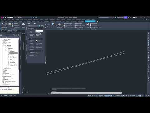
In the world of civil engineering and infrastructure design, precision is the foundation of every successful project. Whether you are mapping out a new roadway, defining a utility corridor, or establishing property boundaries, finding the exact midpoint between two linear features is a frequent necessity. If you are using Civil 3D, you don’t have to rely on manual offsets or tedious geometric calculations to find your center.

Why Automate Your Centerline Creation?

Manually drawing a centerline between two irregular polylines is not only time-consuming but also prone to human error. Even a slight deviation can impact earthwork calculations or drainage slopes. By leveraging the automated geometric tools within Civil 3D, you ensure that your design remains mathematically accurate and dynamically linked to your existing site data.

Step-by-Step: Generating a Centerline

Creating a centerline between two existing polylines is a straightforward process that can significantly speed up your drafting phase. Follow these steps to achieve a clean result:

  1. Prepare Your Source Data: Ensure that the two polylines representing your edges (such as a curb line or a ditch) are clean and do not contain unnecessary overlapping vertices.
  2. Access the Command: While there are various ways to achieve this, many professionals use the "Centerline" command found under the Annotate or Modify tabs, or specific geometric tools within the transparent commands.
  3. Select the Boundaries: Select your first polyline and then the second. The software will calculate the average distance between all corresponding points to generate a new line exactly in the middle.
  4. Refine the Result: Once the line is generated, you can convert it into an Alignment if you need to create profiles or cross-sections later in your design process.

Pro-Tips for Better Accuracy

To get the best results, ensure that your polylines are drawn in the same direction. If one polyline starts at the north and the other at the south, the software may struggle to calculate the relationship between the vertices. Additionally, simplifying the polyline (reducing the number of vertices) before creating the centerline can result in a much smoother, more manageable line.

Mastering these small but essential workflows in Civil 3D will not only improve the accuracy of your technical drawings but also save you hours of manual rework. Start implementing this technique today to streamline your site design and focus on what really matters—building better infrastructure.

Continue Reading | ความคิดเห็น

Essential AutoCAD 3D Basic Settings: A Step-by-Step Beginner's Guide

Wednesday, October 21, 2026

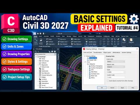
Starting any civil engineering or design project requires a solid foundation. Before you begin drawing lines, generating surfaces, or designing infrastructure, configuring your software workspace correctly is critical. Getting familiar with basic configuration options in Civil 3D 2027 ensures your workflows remain efficient, accurate, and standardized across your team.

Understanding Drawing Settings, Units, and Zones

Setting up your workspace properly prevents costly errors later in the project lifecycle. In modern AutoCAD 3D civil engineering workflows, defining the correct units (feet vs. meters) and drawing scales is the first step toward project accuracy.

Equally important is assigning the correct geographical zone and coordinate system. Setting up geographic transformation settings guarantees that your design aligns seamlessly with real-world spatial data, aerial imagery, and GIS databases.

Managing Drawing Properties and Metadata

Organizing your project data is just as vital as the technical drafting itself. Through the Drawing Properties menu, you can configure crucial metadata, including:

  • Project Title and Description
  • Author and Client details
  • Custom property fields for drawing automation

Maintaining accurate drawing properties streamlines document control, simplifies multi-user collaboration, and automates title block data across your drawing sheets.

Mastering Styles for Visual Consistency

Styles control how drawing elements—such as surfaces, alignments, points, and corridors—are displayed on your screen and in final print outputs. By mastering AutoCAD 3D object and label styles, you can maintain company design standards while keeping your drawing performance optimized. Setting up standard styles early allows you to quickly toggle visual displays on or off, helping you focus on design details without cluttering your drawing area.

Final Thoughts

Taking the time to configure drawing settings, units, properties, and visual styles before modeling will save you hours of troubleshooting later. A properly configured template in AutoCAD 3D gives you complete control over your project data, visual presentation, and spatial accuracy. Make sure to establish these basic settings as a standard practice for every new project!

Continue Reading | ความคิดเห็น

Mastering TUFLOW Ensemble Analysis in Autodesk 3D for Civil Engineers

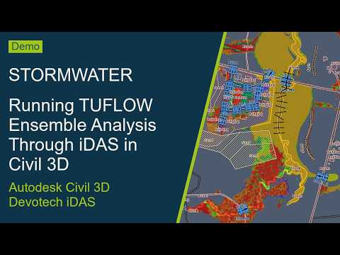
Hydraulic modelling is a cornerstone of modern civil engineering, but identifying critical design conditions is rarely straightforward. To ensure safety and regulatory compliance, engineers must simulate dozens—sometimes hundreds—of storm durations and temporal patterns. Managing this complex workflow can be overwhelming without the right tools. Fortunately, running TUFLOW ensemble analysis directly inside your Autodesk 3D software environment using the iDAS plugin drastically simplifies the process.

Understanding the Power of Ensemble Analysis

In hydraulic and storm design, relying on a single storm event often leads to inaccurate risk assessments. Ensemble analysis allows engineers to evaluate multiple temporal patterns and rainfall durations simultaneously. By modeling these permutations, teams can confidently pinpoint the true critical design conditions, peak water levels, and maximum flow rates across an entire catchment area.

Streamlining Workflows in Autodesk 3D

Traditionally, running extensive TUFLOW simulations required tedious manual data conversion and constant switching between standalone GIS tools and design platforms. By using the iDAS extension within Civil 3D, engineers can set up, execute, and post-process TUFLOW ensemble runs directly within their Autodesk 3D design space. This unified setup eliminates duplicate data entry, reduces human error, and keeps design teams focused on analysis rather than file management.

Key Advantages for Infrastructure Design

Integrating TUFLOW ensemble simulations with iDAS provides clear operational benefits: - Automated Scenario Management: Effortlessly prepare and batch-run various storm duration matrices without leaving your CAD canvas. - Enhanced Spatial Context: Overlay hydraulic depth and velocity results directly onto 3D civil models for clear visualization. - Faster Engineering Decisions: Rapidly isolate governing storm events to refine pipe sizing, basin volumes, and channel capacities early in the design phase.

Conclusion

By incorporating advanced ensemble analysis directly into your Autodesk 3D workflow, hydraulic modelling becomes faster, more accurate, and much easier to iterate. Leveraging tools like iDAS and TUFLOW ensures your stormwater and flood mitigation designs are built on reliable, comprehensive data.

Continue Reading | ความคิดเห็น

Mastering Earthwork Volumes: A Comprehensive Guide to Cut & Fill in Civil 3D

Tuesday, October 13, 2026

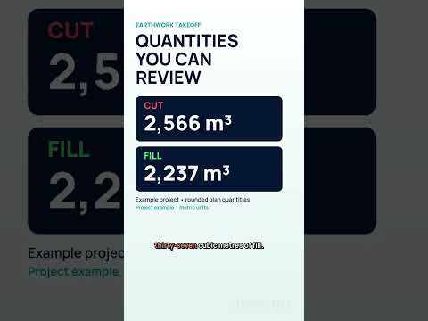
Managing earthwork volumes is one of the most critical aspects of any site development or infrastructure project. Whether you are leveling a site for a new building or grading a residential road, knowing exactly how much soil needs to be moved is vital for staying on budget and on schedule.

The Essentials of Cut and Fill Calculations

In the world of site grading, "cut" refers to the material removed from a location to lower its elevation, while "fill" refers to the material added to raise it. The ultimate goal for many designers is to balance these two figures, minimizing the expensive need to haul material off-site or import new fill from external sources.

By utilizing Civil 3D, engineers and designers can create complex surface models that compare existing ground conditions with proposed designs. This digital comparison allows for precise volume calculations that far exceed the accuracy of traditional manual methods, providing a data-driven foundation for your entire project.

Why Precision in Earthwork Matters

Inaccurate volume estimates can lead to massive logistical headaches and unexpected costs. If you underestimate the "cut" volume, you may find yourself with a surplus of soil and no designated area to store it. Conversely, underestimating the "fill" required means paying for expensive imported material and expedited transportation halfway through construction.

Using professional Civil 3D workflows ensures that your calculations account for every slope, swell factor, and shrinkage rate. This level of detail provides a reliable roadmap for contractors and project managers, allowing them to optimize their machinery and labor resources effectively from day one.

Streamlining Your Deliverables

If you are currently managing a heavy workload, calculating these volumes manually or troubleshooting surface errors can be a bottleneck. Professional earthwork analysis services can provide the clarity you need. High-quality support typically covers:

  • Comprehensive Earthwork Volume Calculations
  • Detailed Existing vs. Proposed Surface Comparisons
  • Accurate Site Grading and Volumetric Reports

By integrating these expert insights into your Civil 3D project, you can move from the design phase to the construction phase with total confidence. Let’s take the guesswork out of your next site plan and ensure your earthwork strategy is as efficient as possible.

Continue Reading | ความคิดเห็น

One-Way vs. Two-Way Slabs Explained: A Guide to Visualization with Civil 3D

Wednesday, September 30, 2026

Concrete slabs are fundamental structural components in civil engineering, forming the floors, roofs, and decks of modern buildings. When planning and visualizing these elements in advanced drafting workflows like Civil 3D, understanding the key differences between one-way and two-way slabs is essential for structural integrity, accurate load estimation, and cost efficiency.

Here is a clear breakdown of how one-way and two-way slabs work, how they differ, and why their design matters.

What is a One-Way Slab?

A one-way slab is a structural element supported primarily on two opposite sides by parallel beams or walls. Because of this support configuration, structural loads are transferred along a single direction.

  • Span Ratio: A slab is categorized as one-way when the ratio of the longer span ($L_y$) to the shorter span ($L_x$) is equal to or greater than 2 ($L_y / L_x \ge 2$).
  • Bending Behavior: The slab bends primarily along its shorter span, forming a cylindrical shape under load.
  • Reinforcement: Main reinforcement steel bars are placed along the shorter direction to resist bending moments, while secondary (distribution) steel is placed along the longer span to withstand temperature changes and shrinkage.

What is a Two-Way Slab?

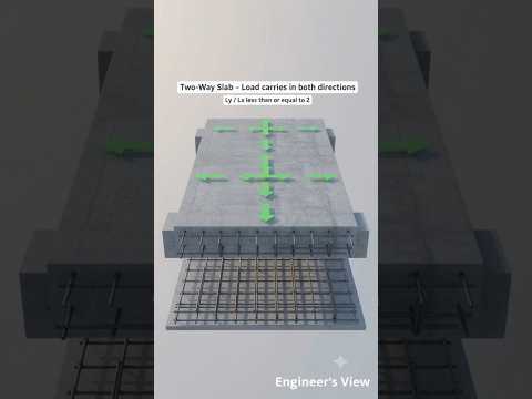
A two-way slab is supported along all four edges by beams or structural walls. As a result, the loads applied to the slab surface are distributed in both orthogonal directions.

  • Span Ratio: A slab acts as a two-way slab when the ratio of the longer span ($L_y$) to the shorter span ($L_x$) is less than 2 ($L_y / L_x < 2$).
  • Bending Behavior: The slab bends in both directions, forming a dish-like or spherical shape under load.
  • Reinforcement: Main reinforcement steel is provided in both directions to accommodate bending moments occurring along both axes.

Key Differences at a Glance

  1. Load Distribution: One-way slabs transfer loads to two supporting beams, whereas two-way slabs distribute loads across four surrounding supports.
  2. Thickness & Material Savings: Two-way slabs are generally thinner and require less concrete volume for the same load capacity due to efficient multidirectional load transfer.
  3. Application: One-way slabs are ideal for long, narrow rectangular spaces (like hallways and verandas), while two-way slabs are commonly used for square or nearly square rooms.

Bridging Structural Analysis and 3D Modeling

Incorporating accurate structural geometries into broader infrastructure and land development project models using Civil 3D allows engineers and site planners to better visualize spatial arrangements, manage elevations, and ensure seamless coordination between civil and structural design teams.

Whether designing small residential platforms or large commercial floor systems, mastering the fundamentals of slab behavior ensures safer, more cost-effective engineering decisions from initial concept to final construction.

Continue Reading | ความคิดเห็น

Mastering Tunnel Design: A Step-by-Step Guide Using 3D CAD and Civil 3D

Saturday, September 12, 2026

Designing a tunnel is often considered one of the most complex challenges in the fields of civil engineering and surveying. From managing underground clearances to ensuring structural integrity, the process demands an incredibly high level of precision. Fortunately, modern 3D CAD technology has revolutionized how we approach these projects. By utilizing Autodesk Civil 3D, engineers can transform complex data into accurate, data-rich models that streamline the entire construction workflow.

Defining the Path: Alignments and Profiles

The first step in any tunnel project within a 3D CAD environment is establishing a precise horizontal alignment and vertical profile. In Civil 3D, this involves more than just drawing lines; it is about creating a dynamic path that reflects the existing terrain and the specific depth requirements of the underground structure. These parameters serve as the backbone of your model, ensuring that every subsequent step—from structural modeling to volume calculations—is anchored to an accurate geometric reference.

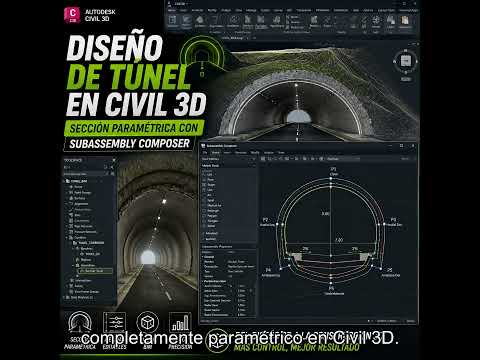
The Power of Assemblies in Tunneling

What truly sets tunnel design apart from standard road design is the "Assembly." In Civil 3D, the assembly represents the cross-section of your tunnel. This includes the structural lining, waterproofing layers, and internal infrastructure such as ventilation, lighting, and drainage systems. Utilizing advanced 3D CAD tools allows you to customize these subassemblies to fit various shapes—whether you are designing a circular TBM (Tunnel Boring Machine) section, a horseshoe shape, or a rectangular box culvert. This flexibility is crucial for adapting to different geological conditions and specific engineering requirements.

Generating the Corridor and Final Visualization

Once the alignment, profile, and assembly are finalized, you can generate the "Corridor." This is the stage where your tunnel design truly comes to life in a three-dimensional space. The corridor integrates all your design data to create a comprehensive model that can be used for cross-section extraction, material takeoff, and clash detection.

By visualizing the tunnel within a professional 3D CAD framework, you can identify potential design flaws or utility conflicts long before the construction phase begins. Mastering these workflows in Civil 3D not only improves your efficiency as a designer but also ensures the highest level of accuracy for large-scale infrastructure projects. Whether you are a seasoned surveyor or a civil engineering student, learning these steps is essential for staying competitive in the modern industry.

Continue Reading | ความคิดเห็น

Mastering 3D CAD: Real Student Feedback on Learning Civil 3D with Dr. Abrar Khalak

Tuesday, September 8, 2026

In the rapidly evolving world of civil engineering and infrastructure design, staying ahead of technical trends is essential. Mastering industry-standard software not only boosts design productivity but also opens up exciting career opportunities. Among these essential technical skills, proficiency in 3D CAD modeling through specialized programs like Autodesk Civil 3D stands out as a game-changer for aspiring and practicing engineers alike.

Why Learn Civil 3D with Dr. Abrar Khalak?

Learning complex engineering software requires more than just basic tutorials; it demands expert mentorship and a structured curriculum. Dr. Abrar Khalak has earned a stellar reputation for delivering comprehensive, practical, and highly engaging Civil 3D training. His teaching approach focuses on real-world practical application, effectively bridging the gap between theoretical engineering concepts and actual project execution.

Through hands-on exercises, students learn how to navigate land development, road design, surveying, and site planning using advanced 3D CAD workflows.

Student Reviews: Key Takeaways and Results

Students who recently completed the Civil 3D training under Dr. Abrar Khalak’s guidance have shared overwhelmingly positive reviews. Here are some of the key highlights expressed in their feedback:

  • Practical Project Experience: Learners appreciated working directly with realistic engineering datasets, gaining the confidence to tackle actual industry challenges.
  • Simplified Learning Curve: Complex technical topics—such as surface creation, corridor design, grading, and pipe networks—were broken down into clear, easy-to-digest lessons.
  • Improved Design Efficiency: Many students noted significant improvements in their workflow speed and accuracy, preparing them for professional engineering roles.

Take Your Engineering Career to the Next Level

Whether you are a university student, a recent graduate, or an experienced professional seeking to upgrade your software expertise, investing in comprehensive 3D CAD education is one of the smartest career moves you can make. Dr. Abrar Khalak’s Civil 3D course equips you with the practical skills and confidence needed to succeed in modern civil design.

Continue Reading | ความคิดเห็น

Popular Posts Today

 
Support : 3Dcadbrowser | Grabcad | 3Dcontentcentral | D | E | F | G
Copyright © 2028. Engineering 3DCad Appication - All Rights Reserved