Cad 3D Category

Next-Gen 3D CAD Viewing and AI Analysis: Secure In-Browser Innovation

Monday, August 31, 2026
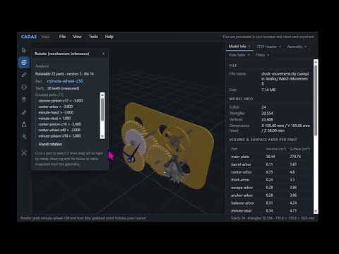
In today's fast-paced engineering environment, manufacturing industries are looking for faster ways to analyze and visualize 3D CAD models. However, many companies face a major hurdle before they can even begin: balancing cutting-edge technology with strict data privacy regulations. Proprietary design data is exceptionally sensitive, making cloud-based uploads a dealbreaker for security-conscious organizations.

Powerful Visualization Directly in Your Browser

CADAS solves this fundamental challenge by providing a seamless solution that allows engineers to open and inspect 3D CAD files directly within their web browser. Traditional workflows often require installing heavy desktop applications or risking intellectual property exposure by uploading files to third-party servers.

With CADAS, complex STEP files are processed entirely on your local machine. Because your design files never leave your PC, enterprise-grade data security is guaranteed without sacrificing the convenience and speed of modern web applications. You get high-performance, real-time visualization right in your browser window.

Unleashing AI Insights Without Compromising Security

While viewing models efficiently is crucial, the real transformation happens when design data meets artificial intelligence. Manufacturers increasingly want to utilize AI to automate cost estimations, identify geometric flaws, and optimize manufacturability. Unfortunately, most conventional AI tools require sending valuable CAD assets to external cloud networks.

CADAS bridges this gap by enabling secure, local AI analysis. By combining localized browser processing with advanced 3D CAD analytics, engineering teams can instantly extract critical manufacturing insights, detect potential production bottlenecks, and streamline design reviews—all while keeping their intellectual property completely offline.

The Future of Secure Engineering Workflows

The future of digital manufacturing lies at the intersection of instant accessibility, intelligent automation, and absolute data privacy. By keeping your design files local while providing browser-based freedom and AI capabilities, CADAS removes the security barriers holding engineering teams back.

It is time to elevate your engineering pipeline: inspect your STEP files effortlessly and unlock the true potential of browser-based AI analysis today.

3D CAD
Continue Reading | ความคิดเห็น

Top SolidWorks Tips to Elevate Your 3D CAD Modeling Skills

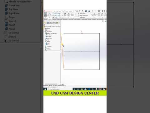
Whether you are a seasoned mechanical engineer or a passionate beginner entering the digital design world, mastering SolidWorks is crucial for producing efficient, high-quality models. As industry standards continue to evolve, staying updated with quick tips and tricks can dramatically speed up your workflow and enhance your technical output.

Why SolidWorks Leads the 3D CAD Industry

SolidWorks remains one of the most powerful and intuitive software solutions used globally across automotive, aerospace, and product design sectors. Utilizing modern 3D CAD tools allows designers to transform complex concepts into precise, functional models with unmatched parametric accuracy. By leveraging advanced assembly techniques, surface modeling, and structural simulations, you can bring even the most intricate engineering visions to life seamlessly.

Essential Tips for Efficient 3D Modeling

To get the most out of your parametric design process, consider integrating these practical habits into your daily workflow:

  1. Optimize Your Sketching: Always fully define your sketches using smart dimensions and geometric relations. This prevents unexpected errors later in the design tree when making parametric modifications.
  2. Master Shortcut Keys: Customize your 'S' key menu and mouse gestures. Minimizing the time spent searching for features on the ribbon toolbar will double your modeling speed over time.
  3. Keep Feature Trees Clean: Name your key features and group related operations into logical folders. A well-organized feature manager tree makes team collaboration smooth and simplifies future revisions.
  4. Utilize Standard Configurations: Take advantage of SolidWorks configurations to create multiple variations of a single part or assembly within one file, saving both time and storage space.

Elevating Your Design Workflow

Mastering 3D CAD software is not just about learning which buttons to press; it is about adopting a structured design mindset. By practicing efficient modeling strategies and continually exploring quick tips, you can significantly reduce design cycle times, minimize manufacturing errors, and create realistic visual prototypes that stand out.

Start implementing these essential SolidWorks tips today, and watch your 3D CAD design efficiency soar to new heights!

3D CAD
Continue Reading | ความคิดเห็น

Master SolidWorks: Essential 3D CAD Modeling Tips for Beginners and Pros

SolidWorks remains one of the most powerful and widely used tools in modern engineering and product design. Whether you are an aspiring maker or an experienced mechanical engineer, mastering 3D CAD software is essential for bringing creative concepts into precise, functional models. From basic geometric sketches to complex parametric assemblies, honing your workflow saves valuable development time while boosting overall project accuracy.

Key SolidWorks Techniques for Speed and Precision

Creating clean, scalable models requires more than just knowing where tools are located—it requires a strong understanding of design intent. Here are fundamental practices to streamline your drafting process:

  • Fully Define Your Sketches: Always ensure your 2D profiles are fully constrained using smart dimensions and geometric relations (such as concentric, parallel, or equal). This prevents accidental shifts later in the design tree.
  • Maintain an Organized Feature Tree: Keep your feature manager organized. Rename key features, group related operations, and avoid unnecessary extrusions or cuts to make future edits hassle-free.
  • Leverage Shortcuts and Hotkeys: Customizing mouse gestures and keyboard shortcuts for frequently used tools like Extrude, Revolve, and Smart Dimension will dramatically speed up your execution.

Elevating Your Projects with Modern 3D CAD Workflows

As you advance beyond basic shapes, adopting structured 3D CAD workflows will significantly improve the quality of your output. Utilizing tools such as global variables and equations allows your models to adapt dynamically whenever specifications change. Furthermore, paying attention to surface fillets and visual materials helps convert basic technical parts into realistic visual assets suitable for presentations.

Consistently practicing these tips ensures your designs are not only visually impressive but also optimized for prototyping, 3D printing, and manufacturing. Investing time in mastering modern 3D CAD capabilities is the best way to sharpen your skills and stand out in the competitive design industry.

3D CAD
Continue Reading | ความคิดเห็น

Mastering Jewelry Design: Crafting a Stunning Krishna Pendant with 3D CAD

Jewelry design has evolved into a breathtaking blend of traditional craftsmanship and digital innovation. Crafting intricate, sacred pieces like a Lord Krishna pendant requires both artistic devotion and exceptional technical precision. Today, the power of modern 3D CAD technology makes it easier than ever for designers to transform complex concepts into photorealistic digital models ready for production.

Designing the Sacred Krishna Pendant

Designing devotional jewelry demands meticulous attention to detail. From the iconic peacock feather and flute to the subtle curves of divine features, utilizing advanced 3D CAD software allows designers to capture delicate elements with unmatched accuracy. Computer-aided design gives artists full creative freedom to experiment with filigree work, surface textures, and gemstone placements long before physically casting the metal.

Bringing Jewelry to Life: Rendering and Animation

Once the digital model is complete, the true visual transformation begins through rendering and animation. High-end rendering software enables designers to apply realistic metal finishes—such as rich yellow gold, warm rose gold, or sleek platinum—and simulate natural studio lighting on every surface.

Creating smooth 360-degree animations brings the Krishna pendant to life from every angle. These animations are not only captivating for potential clients and buyers but also serve as incredible visual material for jewelry CAD design tutorials. Viewers can see every intricate fold of drapery and fine detail in action.

Why Digital CAD Workflows Revolutionize Jewelry Making

Transitioning to digital design tools offers massive advantages for both custom jewelry businesses and CAD enthusiasts: - Unmatched Precision: Ensures accurate dimensions for gem setting and casting. - Enhanced Efficiency: Reduces physical prototyping costs and avoids costly manufacturing errors. - Seamless Visualizing: Allows clients to view accurate 3D renders and request modifications effortlessly.

Whether you are a seasoned goldsmith or a beginner following digital modeling tutorials, mastering 3D CAD skills is essential for turning divine inspiration into wearable art. Dive into 3D jewelry design today and elevate your creative craft to new heights!

3D CAD
Continue Reading | ความคิดเห็น

Master Your 3D CAD Workflow: How to Add Custom Tangent Symbols in SOLIDWORKS

Sunday, August 30, 2026

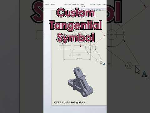
When working on complex engineering projects, precise detailing in technical drawings is essential. While standard software libraries offer a vast range of annotations, modern 3D CAD workflows often require custom geometric dimensioning and tolerancing (GD&T) symbols. A common example is adding a specific tangency relation symbol to clarify design intent in SOLIDWORKS.

In this guide, you will learn how to customize the SOLIDWORKS symbol library file (gtol.sym) to seamlessly integrate your own custom tangent symbols into your drafting environment.

Why Customize Symbols in SOLIDWORKS?

Default drafting symbols do not always meet specialized industry standards or internal company specifications. By adding custom symbols directly into your system files, you can:

  • Maintain Consistency: Keep all engineering drawings aligned with your team's unique annotation standards.
  • Save Time: Eliminate the need to manually draw custom shapes on individual drawing sheets.
  • Improve Clarity: Ensure clear technical communication between design, manufacturing, and 3D printing teams.

Customizing your annotation library is one of the quickest ways to optimize your daily 3D CAD drafting routine and reduce misinterpretation on the production floor.

Step-by-Step: Adding Custom Tangent Symbols to gtol.sym

SOLIDWORKS manages drawing annotations through a text-based library file named gtol.sym. Modifying this file allows you to define new vector-based symbols using simple geometric coordinates.

  1. Locate the Symbol File: Navigate to your SOLIDWORKS system directory. The default path is typically located at C:\ProgramData\SOLIDWORKS\SOLIDWORKS [Version]\lang\english\gtol.sym.
  2. Create a Backup: Before editing, make a copy of the original gtol.sym file. This ensures you can easily restore default settings if an error occurs.
  3. Open in a Text Editor: Open gtol.sym using Notepad or a similar text editing tool.
  4. Add Symbol Definitions: Scroll to an existing category or create a new section for your custom tangent symbol. Define the shape using standard line, circle, and arc syntax supported by SOLIDWORKS.
  5. Save and Restart: Save your changes and launch SOLIDWORKS. Open a drawing document and check the Symbol Library dialog to access your new custom symbol.

Elevate Your Design Precision

Taking full control of your CAD environment drastically reduces drafting friction. Whether you are designing mechanical assemblies or preparing models for advanced fabrication, customizing your 3D CAD tools helps you deliver precise, professional engineering drawings every time.

3D CAD
Continue Reading | ความคิดเห็น

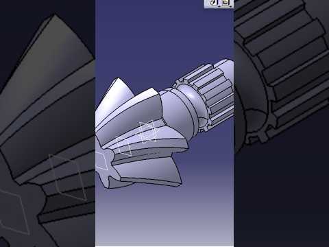
Master Bevel Shaft Design in CATIA V5: Essential 3D CAD Modeling Techniques

Precision engineering begins with accurate digital modeling, and mastering complex mechanical components is essential for any modern designer. Among these components, bevel shafts play a vital role in transmitting power across intersecting axes in various machinery. Learning how to create a detailed bevel shaft using robust 3D CAD software like CATIA V5 is an invaluable skill for mechanical engineers and industrial designers alike.

Understanding the Fundamentals of Bevel Shaft Design

A bevel shaft requires precise angular dimensions, concentric profiles, and exact alignment to ensure smooth power transmission in real-world applications. When building this part in CATIA V5's Part Design workbench, designers must focus on maintaining parametric integrity. By establishing clear geometric constraints during the initial sketching phase, you ensure that any future design modifications can be updated seamlessly.

Essential Steps in the 3D CAD Modeling Workflow

Creating a professional bevel shaft model involves a structured approach within CATIA V5:

  • 2D Sketching & Profile Definition: Begin by creating a fully constrained 2D sketch representing the cross-section of the shaft, paying careful attention to bevel angles and shoulder steps.
  • Shaft (Revolve) Operation: Use the sketch to generate the main solid body by revolving the profile around the central reference axis.
  • Tooth & Geometry Creation: Position custom planes to sketch gear teeth profiles or specialized keyways required for torque transfer.
  • Pocket and Circular Pattern: Execute pocket cuts for gear features and utilize the Circular Pattern tool to replicate the feature uniformly around the circumference.
  • Detailing & Finishing: Apply functional chamfers, edge fillets, and thread definitions to finalize the component.

Adhering to this systematic 3D CAD process reduces design errors and ensures the part is ready for digital assembly or stress analysis.

Elevate Your Mechanical Engineering Skills

CATIA V5 remains an industry standard across aerospace, automotive, and manufacturing sectors due to its unmatched surface and solid modeling capabilities. Mastering essential 3D CAD workflows like bevel shaft modeling empowers you to build complex, production-ready components and accelerates your professional growth in modern CAD design.

3D CAD
Continue Reading | ความคิดเห็น

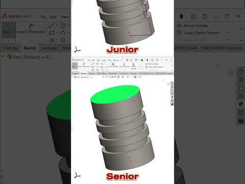
Mastering SolidWorks: Smart Tips and Tricks to Accelerate Your 3D CAD Workflow

In the world of modern engineering and product design, SolidWorks stands out as one of the most powerful software suites available. Whether you are a beginner learning the ropes or an experienced professional, streamlining your design process is key to delivering high-quality models in less time. Mastering 3D CAD software requires more than just knowing the basic commands—it is about leveraging hidden shortcuts, smart features, and workflow optimizations.

Streamline Design with Mouse Gestures and Custom Shortcuts

One of the fastest ways to boost your modeling speed in SolidWorks is by customizing your workspace. Instead of manually navigating through menus to select sketch tools, utilize mouse gestures. By enabling 8 or 12-gesture wheels, you can instantly access frequently used commands like smart dimension, extrude, or rectangle with a quick drag of the mouse. Combining mouse gestures with customized keyboard shortcuts allows you to maintain focus on the graphics area, drastically cutting down on unnecessary clicks.

Optimize Complex Assemblies for Better Performance

As your models grow in complexity, large assemblies can slow down performance and impact productivity. To maintain smooth viewport navigation, take advantage of SolidWorks’ Lightweight Mode and Defeature tools. Loading components as lightweight reduces memory usage by only retrieving model geometry when needed. Furthermore, organizing your FeatureManager Design Tree into sub-assemblies and using freeze bars prevents constant rebuilding, ensuring your 3D CAD environment remains responsive even when handling intricate multi-part projects.

Harness the Power of Smart Dimensioning and Equations

Precision is paramount in parametric modeling. Instead of manually updating dimensions across multiple parts, leverage global variables and equations. By linking critical dimensions together, modifying a single parameter automatically updates your entire model hierarchy. Additionally, using the Instant3D feature lets you drag handles to modify geometry dynamically, giving you real-time visual feedback without opening individual feature dialogs.

Conclusion

Improving your proficiency in 3D CAD design is an ongoing journey. By incorporating these practical SolidWorks tips and tricks into your daily routine, you can eliminate repetitive tasks, improve model accuracy, and significantly shorten project timelines. Start integrating these strategies today and take your 3D modeling skills to the next level!

3D CAD
Continue Reading | ความคิดเห็น

Next-Gen 3D CAD Workflows: In-Browser AI Analysis Without Security Risks

Modern manufacturing relies heavily on digital design files, yet integrating artificial intelligence into design workflows remains a major hurdle for many organizations. While companies are eager to leverage AI insights to speed up production and cut costs, intellectual property concerns often prevent them from uploading sensitive files to third-party cloud platforms. Fortunately, modern 3D CAD tools are changing the game by offering secure, in-browser visualization paired with local AI processing.

Breaking the Data Security Barrier

Traditionally, analyzing design files with advanced algorithms required uploading proprietary STEP files to external cloud servers. For manufacturers handling confidential products or defense-related components, exposing geometry off-site poses unacceptable risks.

A localized browser-based viewer solves this dilemma. Engineers and procurement teams can render and inspect detailed 3D CAD models directly inside a standard web browser—without any file transfer taking place. Because the rendering engine runs locally, your proprietary data stays securely on your PC.

Instant Visualization and Local AI Analysis

Beyond simple file viewing, combining browser technologies with lightweight AI models unlocks unprecedented efficiency. Manufacturing teams can run automated geometric analysis, evaluate manufacturability, and generate instant cost estimates right from their desktop.

Key advantages include: * Maximum IP Protection: Sensitive STEP files remain strictly on local storage, mitigating the risk of data leaks. * Zero Installation Required: High-performance viewing works seamlessly in the browser without installing bulky desktop software. * Accelerated Decision-Making: Instant AI analysis helps bridge the gap between design engineering and manufacturing teams.

The Future of Secure Engineering

As browser performance and AI models become more efficient, teams no longer need to compromise between convenience and security. Adopting privacy-focused 3D CAD solutions allows manufacturers to harness the full power of artificial intelligence while maintaining 100% control over their digital assets.

3D CAD
Continue Reading | ความคิดเห็น

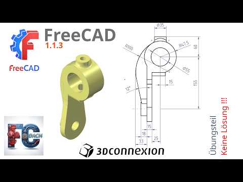
Master FreeCAD 1.1.3: Practical Exercises to Boost Your 3D CAD Skills

Saturday, August 29, 2026

Are you looking to take your parametric modeling skills to the next level? FreeCAD 1.1.3 remains one of the most versatile open-source platforms available today, but reading documentation alone won't turn you into a proficient designer. True expertise comes from practical, hands-on training. In this exercise session, we dive straight into practical workbench workflows designed to help you transform rough ideas into polished, fully constrained models.

Deepen Your Expertise with Hands-On Workbench Practice

Mastering any modern 3D CAD application requires consistent practice and real-world problem-solving. This targeted tutorial focuses on utilizing core workbenches within FreeCAD 1.1.3 to construct precise 3D geometric shapes. By walking through structured exercises step-by-step, you will gain a deeper understanding of how to manage sketch constraints, avoid broken dependencies, and execute clean pad and pocket operations.

Whether you are designing custom replacement parts for 3D printing, working on mechanical engineering projects, or building personal woodworking plans, mastering these foundational techniques ensures your models remain stable and easy to modify down the line.

Boost Navigation and Speed with a SpaceMouse

Achieving peak productivity in 3D CAD software isn't just about knowing keyboard shortcuts—it's also about optimizing your hardware setup. Incorporating a dedicated 3D controller, such as the 3Dconnexion SpaceMouse, can revolutionize how you interact with your digital workspace.

A SpaceMouse allows you to effortlessly pan, zoom, and rotate your 3D models in a single, fluid motion with one hand, while your other hand remains free to select tools, edit dimensions, and input parameters. This two-handed approach not only minimizes repetitive wrist strain but also dramatically accelerates your overall design workflow.

Take Your Modeling to the Next Level

Consistent exercise is the fastest way to build muscle memory and confidence in open-source software. Fire up FreeCAD 1.1.3, follow along with the tutorial video, and apply these essential techniques to your next design project!

3D CAD
Continue Reading | ความคิดเห็น

Next-Gen 3D CAD Workflows: Secure In-Browser Viewing Meets Local AI Analysis

In today’s fast-paced manufacturing landscape, companies are eager to harness the power of artificial intelligence to analyze engineering designs, optimize production, and reduce time-to-market. However, many organizations hit a major roadblock early in the process: data security. Proprietary design files contain valuable intellectual property, making manufacturers hesitant to upload sensitive assets to cloud servers for processing.

CADAS bridges this gap by delivering a powerful solution: analyzing complex 3D CAD files seamlessly in your web browser without ever exposing your confidential data to third-party servers.

Uncompromising Security for Your Proprietary Designs

Traditional cloud-based viewers often require users to upload CAD files to external servers, creating potential security vulnerabilities and compliance issues. CADAS takes a privacy-first approach to data protection. By utilizing local processing power within your browser, your STEP files never leave your PC. You retain complete ownership and control over your technical data while still enjoying fast, high-performance rendering.

Smart AI Analysis Meets Modern Visualization

Beyond mere file viewing, the integration of artificial intelligence opens up new possibilities for engineers and manufacturers. Operating directly within a browser-based 3D CAD viewer, local AI capabilities allow teams to perform automated geometric analysis, evaluate manufacturing feasibility, and extract key design insights in real time.

Instead of waiting for heavy desktop software installations or dealing with tedious file conversions, users can interact with complex models instantly. This local AI processing ensures that actionable insights are generated on the spot, streamlining collaboration between design engineers, procurement teams, and shop-floor technicians.

Accelerate Your Engineering Workflows

By combining client-side privacy with cutting-edge artificial intelligence, CADAS removes the friction that traditionally holds engineering teams back. Manufacturers no longer have to choose between advanced technology and strict data security. You can now unlock the full potential of your 3D CAD workflows without risking sensitive intellectual property.

Whether you are evaluating part geometry, accelerating cost estimation, or simply searching for a secure way to view STEP files, browser-based local analysis represents the future of digital manufacturing.

3D CAD
Continue Reading | ความคิดเห็น

Master Your 3D CAD Projects: How to Save and Export in Sweet Home 3D

Designing a dream home or interior layout is an exciting process, but sharing your vision with clients, contractors, or friends requires the right output formats. While advanced 3D CAD software often comes with a steep learning curve, Sweet Home 3D makes spatial design accessible to everyone. Once your layout is complete, knowing how to properly save and export your project is key to bringing your ideas to life.

In this guide, we will walk you through how to export your floor plans as crisp PDFs, high-resolution rendered images, and dynamic video walkthroughs.

Exporting Crisp PDF Floor Plans

Whether you need physical prints for a construction team or a digital blueprint for a quick client review, exporting your project to PDF is essential. Sweet Home 3D allows you to easily format your 2D grid layout, insert precise measurements, and include detailed furniture lists before saving. This step bridges the gap between quick digital modeling and practical construction, ensuring your spatial dimensions align perfectly with professional 3D CAD standards.

Rendering High-Quality Photorealistic Images

Static 2D plans are great for technical planning, but rendered 3D images are what bring your interior concepts to life visually. Sweet Home 3D offers built-in rendering tools that allow you to customize lighting conditions, shadows, lens attributes, and the time of day. By generating high-definition images of individual rooms, you can showcase materials, color schemes, and lighting setups with impressive clarity before making any real-world renovations.

Producing Immersive Video Walkthroughs

To truly showcase the flow of a house, a video walkthrough is unbeatable. Sweet Home 3D enables users to set customizable camera paths throughout the room layout, recording seamless 3D video tours. This feature transforms your design from a flat diagram into an interactive experience, giving viewers a realistic tour of the virtual property.

Final Thoughts

Mastering these export options ensures that your design workflow remains smooth and professional from start to finish. Whether you are using simple home design software or complex 3D CAD applications, presenting your floor plans through high-quality PDFs, realistic renders, and video tours will elevate your architectural presentations to the next level.

3D CAD
Continue Reading | ความคิดเห็น

Mastering Sweet Home 3D: How to Export Your 3D CAD Designs to PDF, Image, and Video

Designing a dream space is an exciting process, but presenting your vision effectively is what truly brings a project to life. Whether you are an aspiring interior designer, a DIY enthusiast, or a homeowner planning a renovation, knowing how to save and export your work properly is essential. Sweet Home 3D offers an accessible yet powerful platform for creating detailed layouts, making it a popular 3D CAD solution for beginner and intermediate designers alike.

In this quick guide, we will walk you through how to transform your digital blueprints into printable PDF floor plans, high-resolution rendered images, and dynamic video walkthroughs.

Exporting Professional PDF Floor Plans

Once your layout is complete, sharing it with contractors, clients, or family members often requires a clear and standardized document format. Sweet Home 3D allows you to print or export your entire project directly to PDF.

During the export setup, you can customize the layout to include the 2D floor plan, a preview of the 3D view, furniture lists, and precise measurements. This ensures your final document looks clean, organized, and ready for construction or real-world planning.

Rendering High-Resolution 3D Images

Static 2D blueprints are great for technical specifications, but photorealistic visuals are what capture the imagination. By using the photo creation feature, you can render your 3D CAD models into stunning PNG or JPEG snapshots.

To achieve the best results: * Adjust the Lens and Perspective: Position the virtual camera at eye level to create a realistic viewpoint. * Manage Lighting: Set the specific date, time, and geographic location to simulate natural sunlight. You can also add artificial light sources inside rooms to create depth and warm ambiance.

Rendering high-quality images allows you to showcase realistic textures, shadows, and spatial balance before spending a dime on actual materials.

Creating Immersive Video Walkthroughs

Want to give viewers a true sense of scale and flow? Sweet Home 3D includes a built-in video creation tool that lets you record virtual tours of your design.

By setting path points for the virtual camera, you can create a smooth animation moving through different rooms, hallways, and outdoor spaces. Exporting these cinematic walkthroughs elevates your presentation, allowing anyone to experience the space interactively.

Final Thoughts

Mastering these export options turns your 3D CAD projects into professional deliverables that communicate your design vision with precision. Start experimenting with PDF reports, realistic renders, and animated tours today to take your spatial concepts to the next level!

3D CAD
Continue Reading | ความคิดเห็น

Unlocking the Power of AI for 3D CAD: Fast, Secure Analysis in Your Browser

In today's fast-paced manufacturing landscape, companies are eager to harness artificial intelligence to optimize their engineering and production workflows. However, a major bottleneck persists: intellectual property security. Traditional cloud-based solutions often require uploading sensitive design files to external servers, leaving engineering teams hesitant to fully embrace modern AI tools.

Secure Analysis: Keep Your IP Right Where It Belongs

For manufacturers, design data is their most critical asset. The risk of exposing proprietary geometry often prevents teams from leveraging modern automated analysis tools. Browser-based solutions like CADAS solve this challenge by performing processing directly within your web browser.

Because files are analyzed locally on your computer, your STEP files never leave your PC. This local-first approach ensures that proprietary engineering data remains 100% private and secure, giving companies total peace of mind while leveraging intelligent automation.

Seamless Visualization and AI Insights

Having a lightweight, browser-accessible 3D CAD tool eliminates the need for expensive software licenses or heavy installations across non-engineering departments. Project managers, procurement teams, and external partners can view detailed assemblies instantly without friction.

Furthermore, integrating intelligent analysis into a browser-native 3D CAD environment allows teams to automatically check manufacturability, extract metadata, and identify potential design flaws in real time. You get the computational benefits of modern AI without the data privacy risks associated with traditional cloud uploads.

The Future of Secure Manufacturing Tech

As the industry moves toward faster product lifecycles, local-first web technologies bridge the gap between legacy engineering practices and advanced automation. By embedding intelligent analytics directly into your 3D CAD workflow while keeping your data strictly on your local device, manufacturers can safely step into the future of digital engineering.

3D CAD
Continue Reading | ความคิดเห็น

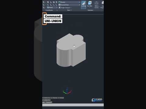
Mastering 3D CAD: How to Use the AutoCAD UNION Command to Combine Solids

Friday, August 28, 2026

When working in modern 3D CAD software like AutoCAD, creating complex shapes often starts with combining simpler geometry. Whether you are designing mechanical parts, architectural elements, or intricate 3D models, knowing how to merge distinct objects into a single continuous solid is a fundamental skill.

That is where the UNION command comes in. In this guide, we will break down how the UNION command works and how you can use it to streamline your 3D modeling workflow.

What is the UNION Command in AutoCAD?

The UNION command in AutoCAD is a Boolean operation used to combine two or more overlapping or adjacent 3D solids, surfaces, or 2D regions into a single, unified object. Instead of managing dozens of individual shapes, UNION allows you to merge them so they act as one single piece.

This is essential for clean geometric design, accurate volume calculations, and preparing models for 3D printing or rendering.

Step-by-Step: How to Combine 3D Objects Using UNION

Combining 3D solids in AutoCAD is straightforward once you know the basic steps:

  1. Prepare Your Geometry: Place two or more 3D solid objects (such as boxes, cylinders, or spheres) so that they intersect or touch each other.
  2. Activate the Command: Type UNION (or UNI) in the command line and press Enter. Alternatively, click the Union tool located on the Solid Editing panel under the 3D Modeling workspace tab.
  3. Select Objects: Click on all the 3D solids you wish to combine. You can select them one by one or use a selection window.
  4. Execute: Press Enter or Spacebar to complete the operation.

Instantly, the intersecting inner lines between the objects will disappear, leaving you with one seamless 3D object.

Why the UNION Command is Essential for 3D CAD Professionals

Mastering Boolean operations like UNION drastically improves your efficiency when working on complex projects. Here are a few key benefits:

  • Simpler Object Management: Moving, rotating, or scaling a single merged object is much easier than selecting multiple separate components.
  • Clean Exporting: Many 3D printing and rendering tools require a watertight, unified mesh to process files correctly.
  • Improved Performance: Reducing the overall object count keeps your drawing files lighter and smoother to navigate.

Whether you are just getting started with 3D CAD or looking to sharpen your existing modeling skills, mastering the UNION command is a crucial step toward creating professional-grade 3D designs. Give it a try in your next AutoCAD project!

3D CAD
Continue Reading | ความคิดเห็น

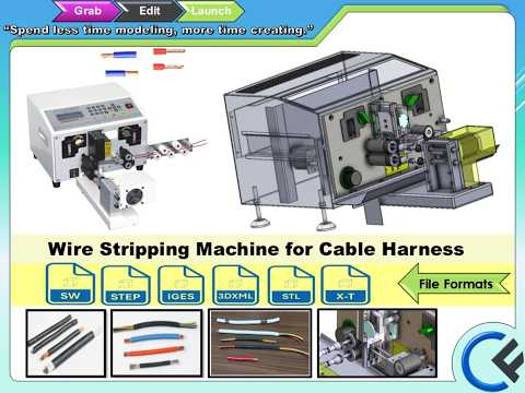
Revolutionizing Wire Processing: How 3D CAD Models Optimize High-Speed Cable Machines

Wednesday, August 26, 2026

In the fast-paced world of industrial automation, efficiency and accuracy are paramount to producing reliable wire harnesses. Automated cable processing machines have become indispensable assets for high-volume manufacturing environments. To achieve seamless operation and pinpoint accuracy, modern machinery relies heavily on advanced engineering design. Utilizing a robust 3D CAD framework allows engineers to visualize every gear, blade, and pneumatic actuator long before physical assembly begins.

Precision Engineering for High-Speed Cable Processing

The SC-0006 wire stripping machine is engineered specifically to handle demanding cable processing workflows. Designed for maximum throughput, it streamlines operations by executing precise strip lengths, handling diverse wire gauges, and preparing conductors for immediate harness assembly.

High-speed wire processing requires absolute mechanical alignment. Minor miscalculations in blade positioning or feeding mechanisms can lead to damaged strands, inconsistent strip lengths, or costly machine downtime. Through comprehensive computer-aided modeling, every structural element is stress-tested and optimized to maintain tight tolerances during continuous, high-speed operation.

Streamlining Harness Assembly Workflows

Integrating custom automation equipment into an existing factory layout can present significant spatial and mechanical challenges. By integrating a digital 3D CAD model into the production workflow, plant engineers can simulate how the wire stripping machine interacts with upstream wire feeders and downstream crimping or bundling stations.

This digital twin approach enables engineering teams to: - Verify spatial requirements and footprint constraints prior to installation. - Plan electrical and pneumatic routing with complete clarity. - Reduce physical prototyping cycles, cutting development costs and time-to-market. - Ensure seamless integration with robotic arms and custom assembly fixtures.

Driving Efficiency in Modern Industrial Design

As demand for complex harness assemblies grows across the automotive, aerospace, and consumer electronics sectors, speed and quality must go hand in hand. Equipment designed with high precision ensures consistent repeatability across millions of operating cycles.

Whether you are designing a full automation line or upgrading specific equipment, leveraging pre-built 3D CAD assets minimizes engineering overhead and prevents costly redesigns on the factory floor. Investing in well-engineered wire processing solutions lays a solid foundation for smarter, faster, and more efficient manufacturing.

3D CAD
Continue Reading | ความคิดเห็น

Unlocking the Power of 3D CAD: How Mechanical Assemblies Come to Life

In the fast-paced world of modern engineering and product design, static 2D blueprints are rapidly becoming a thing of the past. Today, complex machinery and intricate mechanical parts rely heavily on sophisticated visualization tools to ensure perfection before physical production ever begins. This is where modern 3D CAD (Computer-Aided Design) technology plays a pivotal role, transforming abstract concepts into fully interactive, functional mechanical assemblies.

Understanding Mechanical Assemblies in Motion

Designing an individual component is only the first step in product development. The true test of engineering lies in how various moving parts interact within a complete mechanism. Through digital assembly, designers can simulate motion, test real-world constraints, and identify potential mechanical interferences early in the design cycle. Seeing a machine come alive through realistic 3D animations not only accelerates the design process but also drastically reduces costly manufacturing errors.

Why Mastering 3D CAD is Essential for Engineers

Whether you are a student, a professional mechanical engineer, or a passionate hobbyist, developing strong proficiency in 3D CAD opens up limitless possibilities. Modern software allows creators to:

  • Build highly precise 3D geometry and parametric models.
  • Perform virtual stress tests and dynamic motion simulations.
  • Streamline collaboration between design, engineering, and manufacturing teams.

With step-by-step practical learning, mastering complex concepts like gear mechanisms, linkage assemblies, and automated machinery becomes significantly easier and more accessible.

Transform Your Creative Workflow Today

Bridging the gap between theoretical engineering and practical application requires hands-on practice and clear, accessible visual guides. By leveraging modern digital tools and high-quality tutorial content, you can easily turn complex mechanical challenges into seamless, practical design solutions. Start exploring realistic mechanical models today and elevate your engineering capabilities to the next level!

3D CAD
Continue Reading | ความคิดเห็น

How to Open FG Files Easily: A Complete Guide for 3D CAD Users

Have you ever clicked on a Faceted Glass (.fg) file expecting a smooth project preview, only to be greeted by an annoying error message? You are not alone. Facing file format incompatibilities and opening errors is a common challenge for designers, engineers, and digital artists who regularly deal with complex assets.

In this guide, we will walk you through both manual and automatic solutions to open your FG files hassle-free and keep your design workflow running smoothly.

What is a Faceted Glass (FG) File?

An FG file, short for Faceted Glass file, is a specialized file format frequently associated with advanced rendering engines, lighting simulations, and 3D CAD modeling environments. These files store intricate geometric data and surface reflection properties required to generate photorealistic glass materials.

When your operating system does not know which application to assign to the .fg extension—or if the file header is slightly corrupted—it triggers an error message instead of opening the file.

Solution 1: The Manual Fix

If the error occurs because your computer doesn't recognize the file type, you can manually restore the file association in a few simple steps:

  1. Verify the Extension: Ensure the file name ends with .fg and hasn't been accidentally renamed.
  2. Re-associate Default Programs: Right-click the FG file, select Open With, and navigate to your preferred 3D CAD or rendering application. Check the box that says "Always use this app to open .fg files" before clicking OK.
  3. Use Intermediary Formats: If your primary software still refuses to read the file directly, try importing it through a compatible plugin or converting it into a standard exchange format like STEP or OBJ.

Solution 2: The Automatic Fix

If changing the file association doesn't work, the FG file itself may have corrupted header data or missing references. In this scenario, using an automated file repair utility or universal file opener is the most reliable solution.

Automated tools scan the internal architecture of the broken file, repair damaged data blocks, and automatically convert or restore the file so it opens seamlessly in your favorite 3D CAD suite. This approach eliminates technical guesswork and prevents severe project downtime.

Summary

Troubleshooting unexpected file errors shouldn't hold back your productivity. Whether you resolve the issue with a quick manual setting tweak or rely on an automatic repair utility, getting access to your Faceted Glass files is straightforward. Apply these solutions today to unlock your files and continue building your models without interruption!

3D CAD
Continue Reading | ความคิดเห็น

Revolutionize Your 3D CAD Design Reviews: What Is CADchat?

Tuesday, August 25, 2026

In today’s fast-paced engineering and manufacturing landscapes, collaborating on complex product designs can often feel frustrating. Traditional video conferencing platforms like Zoom or Microsoft Teams are great for general discussions, but they fall short when teams need to interact directly with heavy CAD models. Enter CADchat—a game-changing, browser-based collaboration platform designed to streamline your 3D CAD design reviews.

Why Traditional Video Meetings Fall Short for Engineers

For years, hardware teams have relied on screen-sharing static images or attempting to rotate heavy models over video streams that lag, freeze, or suffer from poor visual clarity. This friction leads to miscommunications, delayed approval cycles, and endless email threads. CADchat solves this exact problem by combining Zoom-like video calls with a dedicated environment built specifically for spatial model visualization.

Streamline Real-Time Reviews for 3D CAD Models

Because CADchat operates entirely within your web browser, participants don't need to install heavy desktop software or hold expensive licenses just to review a design. Anyone on your team—from lead engineers to clients and project stakeholders—can join a live meeting with a single click.

During the call, team members can manipulate, measure, and annotate complex 3D CAD assemblies simultaneously in high fidelity without experiencing hardware bottlenecks or video lag.

Key Features of CADchat

  • Browser-Based Accessibility: Join meetings instantly from any modern web browser without downloading heavy plugins or software.
  • Interactive 3D Manipulation: Zoom, pan, rotate, and explode models seamlessly while remaining on camera with your team.
  • Real-Time Markups: Leave contextual notes and dynamic markups directly on the 3D geometry to eliminate miscommunication.
  • Cross-Department Alignment: Bridge the gap between engineering, sales, management, and external vendors effortlessly.

Final Thoughts

By combining seamless real-time video communication with native 3D visualization, CADchat transforms how modern design teams work together. If you are looking for a smarter, faster way to evaluate complex 3D CAD projects and accelerate your product development lifecycle, CADchat is the purpose-built solution you've been waiting for.

3D CAD
Continue Reading | ความคิดเห็น

Mastering Surface Reverse Engineering in 3D CAD: A Complete Guide

In today’s fast-paced product development landscape, bringing physical objects into the digital realm is more essential than ever. Surface reverse engineering bridges this gap by allowing engineers and designers to convert physical components into accurate digital models using advanced 3D CAD technology.

Whether you are working with legacy mechanical parts or intricate organic shapes, understanding how surface reverse engineering works can dramatically streamline your design workflow.

What is Surface Reverse Engineering?

Surface reverse engineering is the process of capturing a physical object’s exact geometry using 3D scanners, then reconstructing those surfaces into a parametric digital model. Unlike basic solid modeling, surface modeling focuses on complex curves, freeform shapes, and aesthetic surfaces that cannot easily be recreated using standard geometric primitives.

By acquiring point cloud or mesh data from a scan, engineers create clean, mathematically precise non-uniform rational B-splines (NURBS) surfaces over the scanned mesh, recreating the physical product with high dimensional accuracy.

Why Is It Essential for Mechanical Design?

Reverse engineering plays a pivotal role across various industries, including automotive, aerospace, industrial design, and consumer electronics. Here is why it is so valuable:

  • Legacy Part Recreation: Fabricate replacement parts for older machinery where original blueprints or digital files no longer exist.
  • Competitive Analysis: Analyze existing market products to improve performance, ergonomics, or manufacturability.
  • Rapid Prototyping: Transition seamlessly between physical clay prototypes and digital designs in modern 3D CAD software environments.
  • Quality Inspection: Compare manufactured physical parts against original design specifications to ensure tight tolerances.

Key Steps in the Reverse Engineering Process

  1. Data Acquisition: High-resolution 3D scanning generates a detailed point cloud or polygon mesh of the physical part.
  2. Mesh Optimization: Clean up noise, fill gaps, and smooth out irregularities in the scanned mesh.
  3. Surface Fitting: Extract key features and build smooth patches over the mesh to capture complex surface contours.
  4. Parametric Integration: Import the reconstructed surfaces into your 3D CAD program (such as SolidWorks) to build fully functional solid models ready for production.

Final Thoughts

Mastering surface reverse engineering unlocks endless possibilities for mechanical design and product innovation. By leveraging high-precision scanning alongside robust modeling tools, engineers can turn physical concepts into digital reality faster and more efficiently than ever before.

3D CAD
Continue Reading | ความคิดเห็น

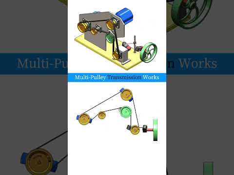
Understanding Multi-Pulley Transmission Systems Through 3D CAD

Mechanical power transmission is at the heart of modern machinery, driving everything from household appliances to massive industrial equipment. Among the various methods used to transfer rotational energy, multi-pulley systems stand out for their efficiency, versatility, and mechanical advantage. But how exactly do these intricate systems work under the hood?

The Mechanics Behind Multi-Pulley Systems

A multi-pulley transmission relies on a series of interlinked wheels (pulleys) connected by belts or cables. By altering the relative diameters of these pulleys, mechanical engineers can precisely control speed and torque outputs throughout a machine.

When a smaller drive pulley rotates a larger driven pulley, the output speed decreases while torque increases. Conversely, driving a smaller pulley increases rotational speed at the cost of torque. Combining multiple pulleys allows machines to achieve complex gear ratios, distribute force across multiple axes, and change the direction of rotation seamlessly.

Visualizing Complex Assemblies with 3D CAD

Historically, understanding and designing intricate mechanical assemblies required physical prototypes and manual draft sketches. Today, modern engineers leverage advanced 3D CAD software to model, simulate, and optimize power transmission systems with extreme accuracy.

By breaking down a multi-pulley setup inside a 3D CAD environment, designers can visualize belt tension, analyze stress distribution, and check for spatial clearance issues long before reaching the production floor. This digital precision drastically reduces engineering errors, minimizes material waste, and accelerates the product development cycle.

Practical Applications in Modern Engineering

Multi-pulley transmission systems are ubiquitous across various industries due to their smooth operation and shock-absorption capabilities:

  • Automotive Engines: Serpentine belt systems utilize multiple pulleys to drive the alternator, power steering pump, and air conditioning compressor simultaneously.
  • Industrial Machinery: Manufacturing equipment relies on multi-pulley setups to regulate conveyor belt speeds and drive heavy machinery.
  • Workshop Tools: Drill presses and metal lathes frequently use stepped multi-pulley drives to allow easy speed adjustments depending on the material being worked on.

Conclusion

Whether you are a student, hobbyist, or professional mechanical designer, mastering how power flows through pulley assemblies is fundamental. By utilizing modern 3D CAD tools, complex mechanical concepts become intuitive visual experiences, bridging the gap between theoretical engineering and real-world application.

3D CAD
Continue Reading | ความคิดเห็น

Transform Your Concepts into Reality with Professional 3D CAD Services

In today's fast-paced engineering and architectural landscapes, precision and clarity are paramount. Whether you are designing a complex mechanical component, developing a residential floor plan, or visualizing a multi-story commercial structure, high-quality technical drawings make all the difference. Transitioning from rough sketches to actionable, error-free blueprints requires specialized expertise—and that is where professional 3D CAD services come into play.

From Accurate 2D Drawings to Detailed Models

Every successful construction or manufacturing project starts with a solid technical foundation. Traditional 2D AutoCAD drafting provides the essential framework, delivering accurate floor plans, structural elevations, and detailed technical schematics. However, modern industries require more than flat dimensions to fully realize a design's potential.

By leveraging advanced 3D CAD modeling, design teams can transform two-dimensional drafting into rich, dynamic spatial representations. This enhanced visualization allows engineers, architects, and project stakeholders to analyze structural relationships, evaluate clearances, and detect potential design clashes long before physical production or construction begins. Consequently, this significantly reduces costly rework and unexpected project delays.

Key Benefits of Professional CAD Modeling

Outsourcing your drafting and modeling requirements to experienced professionals offers several strategic advantages:

  • Unmatched Precision: Professional CAD specialists adhere to strict industry standards, ensuring every dimension, tolerance, and material specification is accurate.
  • Cost and Time Efficiency: Maintaining high-end software licenses and specialized in-house staff can be costly. Partnering with experts streamlines your workflow and accelerates project completion.

  • Enhanced Collaboration: Comprehensive digital models make it easy to communicate complex ideas to clients, contractors, and regulatory boards, fostering seamless collaboration.

Elevate Your Design Capabilities Today

Integrating modern 3D CAD solutions into your development pipeline is essential for staying competitive in today's market. By combining precise 2D drafting with detailed spatial modeling, professional CAD services empower you to present compelling proposals, streamline approvals, and build with complete confidence. Explore our comprehensive drafting and CAD modeling services today to bring your vision to life.

3D CAD
Continue Reading | ความคิดเห็น

How to Open FG Files: Quick Fixes for 3D CAD Users

Monday, August 24, 2026

Have you ever clicked on a Faceted Glass (.FG) file expecting your design to load, only to be greeted by an annoying error message? File format incompatibility and file association issues are common hurdles in the world of 3D CAD design. Fortunately, opening and repairing these files doesn't have to be a frustrating experience.

In this guide, we will walk you through both the manual fix and the automatic solution to get your .FG files opened smoothly.

What is a Faceted Glass (.FG) File?

Faceted Glass (.FG) files are specialized data files typically used to store geometric mesh data, rendering parameters, or structural properties for 3D models. Because they are less common than standard file formats like .STL or .OBJ, your operating system may not know which application to use by default, resulting in execution or loading errors.

Solution 1: The Manual Fix

If you prefer troubleshooting the issue yourself, you can resolve file association errors manually by following these steps:

  1. Re-establish File Association: Right-click the .FG file, select Open With, and choose your primary modeling software. Make sure to check the box that says "Always use this app to open .fg files."
  2. Verify File Integrity: Open the file path settings within your main 3D CAD program to ensure the software is configured to import or render faceted geometry correctly.
  3. Update Drivers and Software: Outdated graphics drivers or older software builds can fail to render complex glass facets properly. Ensure your software and system drivers are fully updated.

Solution 2: The Automatic Solution

If manual troubleshooting takes too long, utilizing an automatic fix is your best alternative. Specialized file repair software and universal file viewers can automatically scan broken .FG files, fix corrupt system registry links, and convert the file into a readable format with a single click.

Using an automatic utility saves you valuable time, allowing you to get back to building and editing your 3D CAD projects without technical interruptions.

Final Thoughts

Don't let a minor file format error derail your project deadline. Whether you opt for a hands-on manual fix or use a reliable automatic repair tool, opening Faceted Glass files is quick and easy once you apply the correct solution.

3D CAD
Continue Reading | ความคิดเห็น

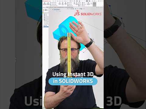
Mastering Instant 3D: Streamline Your 3D CAD Workflow in SOLIDWORKS

Speed and efficiency are crucial when working on complex engineering projects. If you already know how to edit 2D sketch dimensions efficiently, taking the next step into direct 3D feature editing will revolutionize your design process. Using tools like Instant 3D in modern 3D CAD software allows designers to make dynamic modifications without getting bogged down in feature trees and sub-menus.

Here is how you can leverage Instant 3D in SOLIDWORKS to accelerate your design modeling and refine your overall workflow.

What is Instant 3D in SOLIDWORKS?

Instant 3D is a powerful feature in SOLIDWORKS that enables you to quickly modify 3D geometry using onscreen drag handles and dynamic dimension editing. Instead of opening the FeatureManager design tree every time you need to adjust an extrusion depth or cut location, Instant 3D lets you manipulate geometry directly within the graphics area.

This direct-manipulation approach brings a seamless, intuitive feel to your 3D CAD projects, saving valuable time during both early conceptual design and final detailing phases.

Key Benefits of Instant 3D Editing

  • Direct Geometry Manipulation: Click on any feature face to reveal blue drag handles. Simply pull or push these handles to resize extrusions, cuts, or fillets in real-time.
  • On-the-Fly Dimension Adjustments: Double-clicking a feature displays its driving dimensions directly on the model. You can modify numerical values instantly without dropping down into the original 2D sketch level.
  • Ruler Precision Snapping: As you move geometry handles, an integrated visual ruler appears, allowing you to snap dimensions to precise increments effortlessly.

How to Activate and Use Instant 3D

Getting started is simple. Ensure the Instant 3D button is highlighted in the Features tab of your CommandManager.

  1. Resizing Features: Click a feature face, select the triangular handle, and drag it to your desired length.
  2. Editing Dimensions: Click on any feature to display its dimensions, double-click the numerical value, enter the new dimension, and press Enter to see instantaneous updates.
  3. Moving Features: Select a feature on a flat face and drag it to a new location on the same plane.

Boost Your Productivity Today

Integrating Instant 3D into your daily routine is one of the easiest ways to eliminate repetitive clicks and speed up model revisions. Whether you are fine-tuning a quick prototype or updating complex assemblies, mastering these shortcuts ensures your 3D CAD modeling remains fast, flexible, and accurate. Try using Instant 3D on your next SOLIDWORKS model and experience the performance boost firsthand!

3D CAD
Continue Reading | ความคิดเห็น

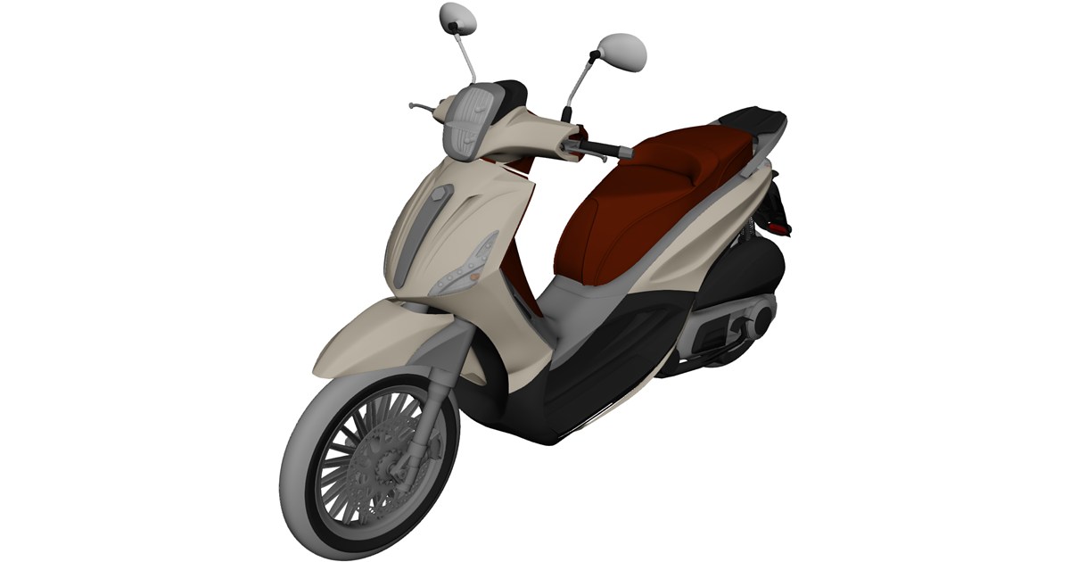
Piaggio Beverly Tourer 200cc Scooter 3D Model

Preview Image

Download the detailed Piaggio Beverly Tourer 200cc Scooter 3D Model, perfectly optimized for automotive visualization, urban scene rendering, CGI animation, and real-time game development.

Key Features & Compatibility:

  • Universal Format Support: Compatible with major 3D software including Blender, 3ds Max, Maya, Cinema 4D, Unreal Engine, and Unity.
  • Versatile Use Cases: Perfect for architectural visualizations, VR/AR interactive applications, digital twin simulations, and game assets.
  • Optimized Design: Built with realistic proportions and flexible topology suitable for both high-end rendering and real-time engines.

Elevate your digital environment by adding this realistic modern urban scooter asset to your 3D library.


Continue Reading | ความคิดเห็น

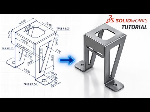
Master 3D CAD: How to Convert 2D Drawings into SOLIDWORKS Sheet Metal Models

Transitioning from 2D engineering drawings to fully realized 3D models is a crucial skill for modern design engineers, fabricators, and draftspersons. Whether you are upgrading legacy blueprints or streamlining your manufacturing workflow, leveraging modern 3D CAD software like SOLIDWORKS can significantly boost design accuracy and productivity.

In this article, we explore how to seamlessly transform a detailed 2D engineering drawing into an accurate, production-ready 3D sheet metal bracket.

The Advantage of 3D Sheet Metal Design

Why transition from traditional 2D blueprints to 3D modeling? Working directly in a 3D CAD environment allows designers to visualize complex spatial relationships, detect component interferences early, and automatically calculate sheet metal bend allowances.

When manufacturing sheet metal parts like mounting brackets, precision is everything. A single miscalculated bend angle or incorrect flat pattern layout in 2D can result in wasted material and costly shop-floor delays. Translating these designs into 3D guarantees that every flange, hole cutout, and bend line aligns perfectly before reaching production.

Key Steps to Convert a 2D Drawing into a 3D Model

To turn a standard 2D drawing into a parametric 3D sheet metal bracket, follow this simplified workflow inside SOLIDWORKS:

  1. Analyze the Blueprint: Carefully review all dimensions, material thickness callouts, and inside bend radii specified in the original 2D engineering draft.
  2. Establish the Base Profile: Recreate or import the foundational view as a fully defined 2D sketch.
  3. Generate Sheet Metal Features: Use the Base Flange/Tab tool to establish the initial sheet thickness. From there, build the bracket's structure using Edge Flanges and Miter Flanges matching the blueprint specs.
  4. Detail Cutouts and Hole Patterns: Add mounting holes, slots, or weight-reduction cuts using standard feature cuts across the sheet metal faces.
  5. Verify the Flat Pattern: Switch to the flattened state to confirm that bend lines, relief cuts, and overall blank dimensions match manufacturing requirements.

Elevate Your Design Capabilities

Mastering the transition from flat 2D drafts to functional 3D models is an invaluable asset for any engineer. By incorporating advanced 3D CAD workflows into your daily operations, you reduce physical prototyping costs, minimize manufacturing errors, and accelerate product development from concept to final assembly.

3D CAD
Continue Reading | ความคิดเห็น

Popular Posts Today

 
Support : 3Dcadbrowser | Grabcad | 3Dcontentcentral | D | E | F | G
Copyright © 2028. Engineering 3DCad Appication - All Rights Reserved