Cad 3D Category

Showing posts with label Technical Drawing. Show all posts

Master Your 3D CAD Workflow: How to Add Custom Tangent Symbols in SOLIDWORKS

Sunday, August 30, 2026
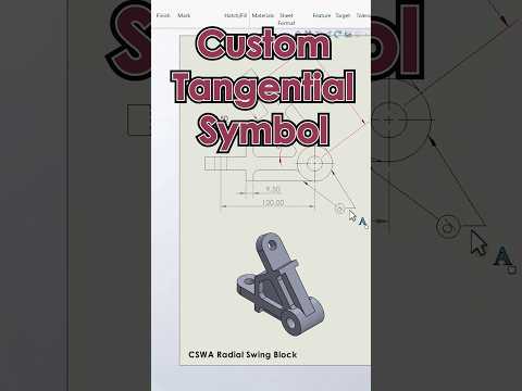
When working on complex engineering projects, precise detailing in technical drawings is essential. While standard software libraries offer a vast range of annotations, modern 3D CAD workflows often require custom geometric dimensioning and tolerancing (GD&T) symbols. A common example is adding a specific tangency relation symbol to clarify design intent in SOLIDWORKS.

In this guide, you will learn how to customize the SOLIDWORKS symbol library file (gtol.sym) to seamlessly integrate your own custom tangent symbols into your drafting environment.

Why Customize Symbols in SOLIDWORKS?

Default drafting symbols do not always meet specialized industry standards or internal company specifications. By adding custom symbols directly into your system files, you can:

  • Maintain Consistency: Keep all engineering drawings aligned with your team's unique annotation standards.
  • Save Time: Eliminate the need to manually draw custom shapes on individual drawing sheets.
  • Improve Clarity: Ensure clear technical communication between design, manufacturing, and 3D printing teams.

Customizing your annotation library is one of the quickest ways to optimize your daily 3D CAD drafting routine and reduce misinterpretation on the production floor.

Step-by-Step: Adding Custom Tangent Symbols to gtol.sym

SOLIDWORKS manages drawing annotations through a text-based library file named gtol.sym. Modifying this file allows you to define new vector-based symbols using simple geometric coordinates.

  1. Locate the Symbol File: Navigate to your SOLIDWORKS system directory. The default path is typically located at C:\ProgramData\SOLIDWORKS\SOLIDWORKS [Version]\lang\english\gtol.sym.
  2. Create a Backup: Before editing, make a copy of the original gtol.sym file. This ensures you can easily restore default settings if an error occurs.
  3. Open in a Text Editor: Open gtol.sym using Notepad or a similar text editing tool.
  4. Add Symbol Definitions: Scroll to an existing category or create a new section for your custom tangent symbol. Define the shape using standard line, circle, and arc syntax supported by SOLIDWORKS.
  5. Save and Restart: Save your changes and launch SOLIDWORKS. Open a drawing document and check the Symbol Library dialog to access your new custom symbol.

Elevate Your Design Precision

Taking full control of your CAD environment drastically reduces drafting friction. Whether you are designing mechanical assemblies or preparing models for advanced fabrication, customizing your 3D CAD tools helps you deliver precise, professional engineering drawings every time.

3D CAD
Continue Reading | ความคิดเห็น

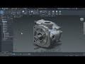
Mastering Mechanical Design: Step-by-Step 3D CAD Assembly & Technical Drawing Guide

Tuesday, August 18, 2026

Mechanical engineering relies heavily on turning complex concepts into tangible, functional components. Whether you are an aspiring engineer, student, or seasoned designer, mastering the full workflow in modern 3D CAD software is essential for bringing your ideas to life with speed and precision.

In this comprehensive breakdown, we explore an end-to-end mechanical design process—from part inspection to complex mechanical assembly and detailed technical drawing generation.

Navigating the Mechanical Assembly Workflow

Building a multi-part mechanical system requires more than just creating individual 3D geometries; it demands a clear understanding of how components interact. During the assembly phase, designers must apply correct mate conditions, mechanical constraints, and alignment checks to ensure smooth kinematic performance.

By utilizing advanced 3D CAD tools, engineers can inspect internal clearances, analyze dynamic motion, and detect component interference long before a physical prototype is manufactured. This digital prototyping phase significantly minimizes material waste and speeds up development cycles.

Translating 3D Models into Precise Technical Drawings

Once your 3D mechanical assembly is finalized, the next crucial step is generating shop-ready manufacturing documentation. A functional digital model relies on standardized 2D blueprints so machinists and technicians can produce parts accurately.

Key aspects of the drawing breakdown include: - Orthographic & Section Views: Generating top, front, and cross-sectional views to reveal internal geometry. - Exploded Views & BOMs: Creating detailed Bill of Materials (BOM) tables and exploded assembly views for seamless assembly lines. - Dimensioning & Tolerancing: Applying essential geometric dimensions and tolerances (GD&T) to guarantee perfect fit and function.

Elevate Your Engineering Workflow

Adopting an integrated, parametric workflow ensures that your design intent remains intact throughout the project lifecycle. When a single parameter changes in a part model, your high-level assembly and 2D blueprints automatically update. Developing proficiency in 3D CAD empowers you to deliver professional, industry-standard engineering deliverables efficiently.

3D CAD
Continue Reading | ความคิดเห็น

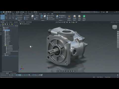
Mastering Mechanical Assembly: A Step-by-Step 3D CAD Workflow Guide

Modern engineering relies heavily on digital precision, and mastering a full mechanical design workflow is essential for creating reliable, production-ready parts. Whether you are an aspiring engineer, a product designer, or a seasoned draftsperson, understanding how to transition from individual components to a complete mechanical assembly is a game-changer. In this breakdown, we walk you through the essential steps of building mechanical assemblies and generating detailed technical drawings using 3D CAD software.

1. Building and Inspecting Mechanical Assemblies

The design process begins by bringing individual parts into a single digital environment. Instead of viewing components in isolation, creating a complete assembly allows you to inspect how mating surfaces interact, verify clearances, and eliminate physical interference before manufacturing ever begins.

Utilizing powerful 3D CAD tools, designers can apply parametric constraints—such as concentricity, coincidence, and distance mates—to simulate real-world mechanical motion. Inspecting the model at this stage ensures that moving parts function smoothly and that every fastener, gear, and housing fits perfectly within the specified tolerances.

2. Translating 3D Models into Precise Technical Drawings

Once the digital assembly is finalized, the next vital step is converting the complex model into standardized 2D technical drawings. While the three-dimensional representation provides visual clarity, shop floor technicians rely on 2D drawings for exact dimensions, geometric tolerances, material specifications, and step-by-step assembly instructions.

A comprehensive technical drawing breakdown includes: * Exploded Views: Clearly displaying how each individual component fits into the overall assembly. * Bill of Materials (BOM): An itemized list detailing part numbers, quantities, and materials needed for production. * Section and Detail Views: Revealing internal geometry and intricate features that are hidden in standard orthogonal views.

3. Elevating Your Design Efficiency

Adopting a structured workflow in 3D CAD drastically reduces design iteration time and prevents costly errors during production. By mastering both assembly inspection and technical drafting, you bridge the gap between abstract conceptualization and real-world manufacturing. Start applying these step-by-step techniques today to streamline your engineering projects and produce professional-grade designs.

3D CAD
Continue Reading | ความคิดเห็น

Popular Posts Today

 
Support : 3Dcadbrowser | Grabcad | 3Dcontentcentral | D | E | F | G
Copyright © 2028. Engineering 3DCad Appication - All Rights Reserved