
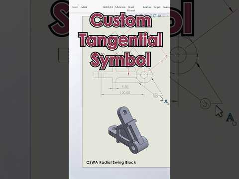
When working on complex engineering projects, precise detailing in technical drawings is essential. While standard software libraries offer a vast range of annotations, modern 3D CAD workflows often require custom geometric dimensioning and tolerancing (GD&T) symbols. A common example is adding a specific tangency relation symbol to clarify design intent in SOLIDWORKS.
In this guide, you will learn how to customize the SOLIDWORKS symbol library file (gtol.sym) to seamlessly integrate your own custom tangent symbols into your drafting environment.
Why Customize Symbols in SOLIDWORKS?
Default drafting symbols do not always meet specialized industry standards or internal company specifications. By adding custom symbols directly into your system files, you can:
- Maintain Consistency: Keep all engineering drawings aligned with your team's unique annotation standards.
- Save Time: Eliminate the need to manually draw custom shapes on individual drawing sheets.
- Improve Clarity: Ensure clear technical communication between design, manufacturing, and 3D printing teams.
Customizing your annotation library is one of the quickest ways to optimize your daily 3D CAD drafting routine and reduce misinterpretation on the production floor.
Step-by-Step: Adding Custom Tangent Symbols to gtol.sym
SOLIDWORKS manages drawing annotations through a text-based library file named gtol.sym. Modifying this file allows you to define new vector-based symbols using simple geometric coordinates.
- Locate the Symbol File: Navigate to your SOLIDWORKS system directory. The default path is typically located at
C:\ProgramData\SOLIDWORKS\SOLIDWORKS [Version]\lang\english\gtol.sym. - Create a Backup: Before editing, make a copy of the original
gtol.symfile. This ensures you can easily restore default settings if an error occurs. - Open in a Text Editor: Open
gtol.symusing Notepad or a similar text editing tool. - Add Symbol Definitions: Scroll to an existing category or create a new section for your custom tangent symbol. Define the shape using standard line, circle, and arc syntax supported by SOLIDWORKS.
- Save and Restart: Save your changes and launch SOLIDWORKS. Open a drawing document and check the Symbol Library dialog to access your new custom symbol.
Elevate Your Design Precision
Taking full control of your CAD environment drastically reduces drafting friction. Whether you are designing mechanical assemblies or preparing models for advanced fabrication, customizing your 3D CAD tools helps you deliver precise, professional engineering drawings every time.

