
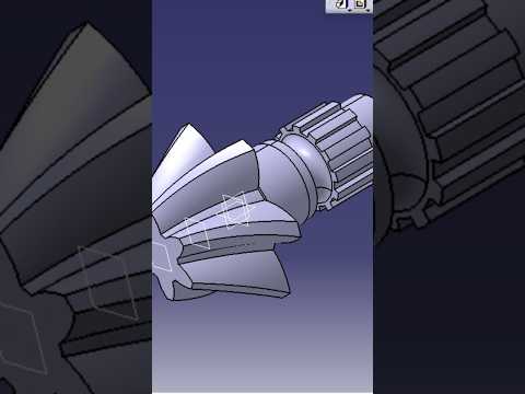
Precision engineering begins with accurate digital modeling, and mastering complex mechanical components is essential for any modern designer. Among these components, bevel shafts play a vital role in transmitting power across intersecting axes in various machinery. Learning how to create a detailed bevel shaft using robust 3D CAD software like CATIA V5 is an invaluable skill for mechanical engineers and industrial designers alike.
Understanding the Fundamentals of Bevel Shaft Design
A bevel shaft requires precise angular dimensions, concentric profiles, and exact alignment to ensure smooth power transmission in real-world applications. When building this part in CATIA V5's Part Design workbench, designers must focus on maintaining parametric integrity. By establishing clear geometric constraints during the initial sketching phase, you ensure that any future design modifications can be updated seamlessly.
Essential Steps in the 3D CAD Modeling Workflow
Creating a professional bevel shaft model involves a structured approach within CATIA V5:
- 2D Sketching & Profile Definition: Begin by creating a fully constrained 2D sketch representing the cross-section of the shaft, paying careful attention to bevel angles and shoulder steps.
- Shaft (Revolve) Operation: Use the sketch to generate the main solid body by revolving the profile around the central reference axis.
- Tooth & Geometry Creation: Position custom planes to sketch gear teeth profiles or specialized keyways required for torque transfer.
- Pocket and Circular Pattern: Execute pocket cuts for gear features and utilize the Circular Pattern tool to replicate the feature uniformly around the circumference.
- Detailing & Finishing: Apply functional chamfers, edge fillets, and thread definitions to finalize the component.
Adhering to this systematic 3D CAD process reduces design errors and ensures the part is ready for digital assembly or stress analysis.
Elevate Your Mechanical Engineering Skills
CATIA V5 remains an industry standard across aerospace, automotive, and manufacturing sectors due to its unmatched surface and solid modeling capabilities. Mastering essential 3D CAD workflows like bevel shaft modeling empowers you to build complex, production-ready components and accelerates your professional growth in modern CAD design.

