
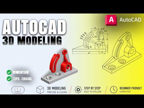
Designing mechanical components requires precision, efficiency, and a solid grasp of core modeling tools. Whether you are an aspiring mechanical engineer or a seasoned draftsman looking to sharpen your skills, practicing real-world component design is the best way to improve. In this guide, we explore how to create a detailed mechanical mounting bracket, offering an ideal exercise to strengthen your 3D CAD abilities.
Fundamental Tools for 3D Mechanical Modeling
Building complex mechanical parts in AutoCAD relies on mastering a few fundamental 3D commands. A mounting bracket, for instance, tests your ability to combine base shapes, create precise cutouts, and align geometries effectively.
Key operations featured in this practice exercise include: - Extrude: Transforming 2D cross-sections into 3D solid objects. - Subtract: Removing internal geometries to create mounting holes, counterbores, and slots. - Presspull: Dynamically modifying faces and extruding bounded areas for rapid design iteration. - Union: Combining multiple distinct solids into a unified, single component.
By understanding how these tools interact, you can approach even the most intricate mechanical blueprints with clarity and confidence.
Step-by-Step Approach to the Bracket Design
To begin modeling the bracket, start by establishing the primary 2D profile. Accuracy at this stage is critical, as any dimensional error in the base sketch will carry over to the final 3D model.
- Draft the Base Profile: Draw the foundational 2D outline of the bracket using accurate dimensions and centerlines.
- Convert to 3D Solids: Apply the
EXTRUDEorPRESSPULLcommand to add depth to the base plate and upright support structures. - Incorporate Feature Cutouts: Utilize boolean operations like
SUBTRACTto carve out bolt mounting holes and center clearance slots. - Refine and Inspect: Apply fillets or chamfers to sharp edges to optimize structural integrity, then switch visual styles to inspect your solid model from multiple angles.
Elevate Your Mechanical Design Skills
Mastering modern 3D CAD workflows isn't just about learning software commands; it is about developing a structured, logical approach to 3D spatial problem-solving. Completing practical hands-on exercises helps bridge the gap between theoretical knowledge and workplace execution.
Take time to work through this mechanical mounting bracket exercise, experiment with varied dimensions, and continue building your proficiency in 3D CAD modeling today!

