
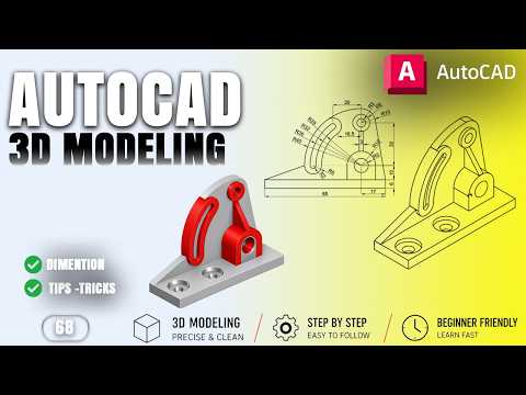
Are you looking to level up your mechanical engineering skills or master computer-aided design? Transitioning from 2D drafting to solid modeling is one of the most rewarding steps in modern engineering. By leveraging power-packed 3D CAD software like AutoCAD, you can transform flat conceptual sketches into highly accurate, detailed mechanical components ready for manufacturing.
In this practical guide, we will explore the fundamental steps and techniques required to model a detailed mechanical mounting bracket from scratch.
Essential Tools for Mechanical Solid Modeling
Creating robust mechanical parts relies on mastering a few core solid modeling operations. When working on a mounting bracket or similar mechanical component, you will frequently utilize:
- Extrude: Convert basic 2D closed polylines into 3D solid shapes by adding height or depth.
- Subtract: Hollow out sections, create bolt holes, or carve keyways by subtracting one solid shape from another.
- Union & Intersect: Combine multiple distinct solids into a single unified object or extract overlapping geometries.
Understanding how these boolean operations interact allows you to build sophisticated components out of simple geometric primitives.
Designing a Mechanical Mounting Bracket Step-by-Step
To build a realistic mechanical mounting bracket, precision is key. Follow these practical stages during your modeling workflow:
- Draft the Base Profile: Start in a 2D view by sketching the base plate and side support ribs with exact dimensions.
- Convert to 3D: Apply the Extrude tool to give thickness to your base and vertical mounting walls.
- Add Fastener Holes: Draw 2D circles at the designated mounting points, extrude them through the solid body, and apply the Subtract command to generate precise screw clearance holes.
- Refine and Fillet: Smooth sharp outer edges using the Fillet Edge command to reduce stress concentrations in your 3D CAD model.
Tips for an Efficient Modeling Workflow
Mastering 3D CAD modeling requires both technical knowledge and disciplined habits. Always ensure your 2D sketches are properly closed before extruding to avoid mesh or surface errors. Additionally, utilize custom User Coordinate Systems (UCS) when placing features on angled surfaces, and regularly switch visual styles (from Wireframe to Conceptual or X-Ray) to inspect your model's internal geometry.
With consistent practice on real-world projects like mounting brackets, you will quickly develop the speed and confidence needed for professional mechanical design.

