Cad 3D Category

Showing posts with label 3D Modeling. Show all posts

Mastering Jewelry CAD: Creating a Stunning Baguette Twin Shank Ring with Rhino 3D

Sunday, September 20, 2026

Jewelry design has entered a new era of precision and creativity thanks to advanced digital tools. One of the most elegant designs to master is the Baguette Twin Shank Ring—a piece that combines architectural symmetry with the timeless brilliance of step-cut diamonds. In this guide, we explore the intricate process of bringing this sophisticated vision to life through professional CAD techniques.

The Architecture of the Twin Shank

The beauty of a twin shank ring lies in its structural complexity. Unlike a traditional single band, the twin shank requires a delicate balance to ensure both bands flow harmoniously toward the center setting. The process begins with establishing the base finger rail and sweeping the profiles. Precision is key here; the gap between the shanks must be consistent to maintain the "light" and "airy" aesthetic that makes this style so popular in modern fine jewelry.

Setting Baguette Stones with Rhino 3D

Baguette diamonds demand a high level of accuracy because of their straight edges and specific geometric proportions. Using Rhino 3D, designers can meticulously align each stone within the channel or prong setting. This software allows for the exact calculation of metal thickness and stone spacing, ensuring that the final cast piece requires minimal manual cleanup. When working with twin shanks, the transition point where the stones meet the dual bands is the most critical area to refine, requiring a smooth surface flow to ensure wearer comfort.

Pro-Tips for a Flawless Workflow

To elevate your jewelry design game, focus on your Boolean operations and history-enabled modeling. By utilizing the robust toolset available in Rhino 3D, you can create parametric-like adjustments. For instance, if you decide the baguette stones need to be slightly larger or the shank needs a different taper, having a clean, organized workflow allows you to make these changes without rebuilding the entire model from scratch. Always remember to check your tolerances for 3D printing; a design that looks flawless on the screen must also be structurally sound for casting in gold or platinum.

Conclusion

The Baguette Twin Shank Ring is a testament to how modern technology meets traditional craftsmanship. Mastering this specific style will not only sharpen your technical skills but also expand your design repertoire for high-end clients. By combining artistic vision with the power of digital modeling, the possibilities for innovation are endless.

Continue Reading | ความคิดเห็น

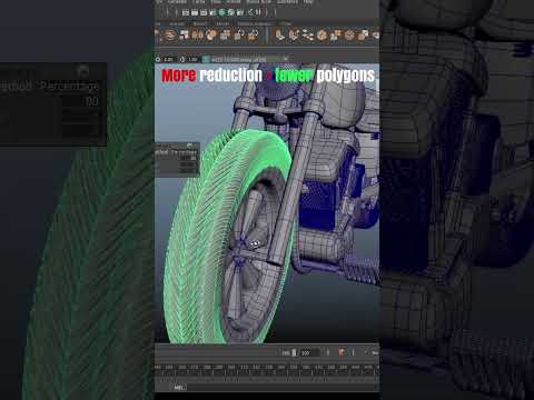
Mastering Digital Creation: Why Maya 3D is the Industry Standard for Artists

Saturday, September 19, 2026

In the rapidly evolving world of digital media, one software package stands out as the ultimate powerhouse for professionals: Maya 3D. From blockbuster Hollywood films to top-tier AAA video games, this comprehensive suite from Autodesk has become synonymous with high-end visual effects, complex character animation, and stunning digital environments.

The Versatility of Professional Modeling

Whether you are an aspiring artist or a seasoned professional, the modeling capabilities found within this software are unparalleled. It provides a robust set of tools for polygonal, NURBS, and subdivision surface modeling. Its ability to handle intricate details while maintaining a streamlined workflow allows artists to bring even the most complex concepts to life. With features like the integrated Modeling Toolkit and advanced UV mapping, the transition from a simple primitive shape to a hyper-realistic character is smoother than ever. Using Maya 3D allows for a level of precision that is essential for modern CGI production.

Industry-Leading Animation and VFX

Beyond static models, the real magic happens when things start to move. The platform is widely regarded as the gold standard for character rigging and animation. Its sophisticated physics engines and procedural toolsets allow for the creation of breathtaking effects—from realistic water simulations to complex motion graphics. For VFX artists, the software offers a deep level of control over lighting, shading, and rendering, ensuring that every frame meets the highest cinematic standards.

Getting Started on Your Creative Journey

Learning a tool this powerful can seem daunting at first, but the rewards are well worth the effort. The community surrounding the software is vast, offering countless tutorials and resources for those looking to sharpen their skills. By mastering the fundamentals of the interface and understanding the core production pipeline, you can open doors to career opportunities in film, gaming, and architectural visualization.

If you are ready to push the boundaries of what is possible in the digital realm, embracing the tools provided by Maya 3D is the definitive first step toward becoming a world-class creator. Whether you are interested in shorts, feature films, or interactive media, the power to create is at your fingertips.

Continue Reading | ความคิดเห็น

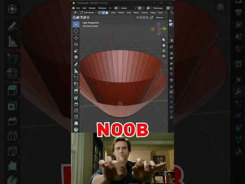
Blender Noob vs PRO: Level Up Your 3D Geometry with Bridge Secrets

Thursday, September 17, 2026

Connecting faces or filling gaps in Blender is one of the most common tasks every 3D artist encounters. While beginners often resort to tedious, manual face creation, professionals use fast and efficient workflow tricks. Mastering tools like Bridge Edge Loops allows you to clean up complex 3D geometry in seconds rather than minutes.

Whether you are building hard-surface assets or organic character models, learning how to bridge faces efficiently will transform your workflow from a Blender beginner into a seasoned pro.

The Beginner Trap vs. The Pro Approach

When starting out, most beginners select individual edges and press the F key repeatedly to build face by face. While this method works for simple flat shapes, it quickly becomes a nightmare when working with curved surfaces, hollow structures, or intricate meshes.

PRO artists, on the other hand, rely on the Bridge Edge Loops feature. By simply selecting two opposite edge loops or face regions and calling the tool, Blender automatically generates clean connecting quads between the selection. This single shortcut dramatically reduces modeling time and prevents topological errors.

Unlocking Secret Bridge Options

The real magic happens right after you execute the bridge tool. By opening the Operator Panel in the bottom-left corner of the viewport, you unlock several hidden controls:

  • Number of Cuts: Instead of a flat bridge, increase the cut count to add automatic subdivisions across the newly created section.
  • Interpolation & Profile Factor: Adjust these parameters to turn straight bridges into smoothly curved arches, pipes, or organic forms without manual sculpting.
  • Twist Offset: If your generated faces look crossed or inverted, adjusting the twist offset instantly fixes misaligned 3D geometry.

Elevate Your Modeling Workflow

Understanding how to manipulate and connect mesh elements efficiently is fundamental to high-level 3D design. By moving away from manual face creation and leveraging Blender's powerful bridging capabilities, you ensure clean, subdivision-ready 3D geometry that renders beautifully and remains easy to edit.

Give these quick bridge secrets a try in your next Blender project, and watch your 3D modeling speed double instantly!

Continue Reading | ความคิดเห็น

Unlock Efficient 3D Modeling: How Mesh Design and Arrays Work Together

Wednesday, September 16, 2026

Creating detailed 3D models from scratch can often feel time-consuming and tedious. Fortunately, modern mesh design workflows leverage clever techniques like mesh arrays to streamline the creative process. Whether you are building intricate architecture or sci-fi environments, mastering array tactics will dramatically improve your 3D modeling pipeline.

Building Complexity with Mesh Arrays

What exactly is a mesh array? Instead of manually copying, pasting, and placing individual objects, an array modifier allows you to repeat a single base object multiple times with exact precision. For instance, duplicating a single base mesh 14 times can instantly construct a complex structure—such as a futuristic corridor, a circular staircase, or a detailed industrial railing. By applying smart mesh design principles, you reduce file clutter, lower scene overhead, and save countless hours of manual alignment.

Effortless Editing and Seamless Updates

The real magic of using arrays lies in global editing. When working with linked instances, any tweak applied to the original base mesh automatically propagates across every single repeated instance in your scene.

If you decide to bevel an edge, adjust a vertex, or refine a bevel on the source piece, all 14 instances update instantly in real time. This dynamic approach completely eliminates repetitive design issues, ensuring perfect consistency throughout your entire project without forcing you to redo tedious work.

Elevate Your 3D Modeling Workflow

Don't let repetitive tasks slow down your artistic vision. By adopting array-based mesh design techniques, you can construct complex, highly detailed 3D environments in a fraction of the time while maintaining total editability over your final output. Start implementing mesh arrays today to make your digital design workflow smarter and much more efficient!

Continue Reading | ความคิดเห็น

Mastering Advanced Sketching: Pro Tips and Tricks for CAD Software Users

Sunday, September 13, 2026

Sketching is the fundamental building block of any 3D model. Whether you are designing a simple bracket or a complex mechanical assembly, the efficiency and stability of your final product depend heavily on how you approach the initial 2D layout. For professionals and hobbyists alike, mastering the nuances of your CAD software is the secret to moving from basic designs to high-level engineering.

Rethinking Your Sketching Strategy

Many users fall into the habit of using the same basic tools for every project. However, advanced sketching is about more than just drawing lines and circles; it is about intent and flexibility. Instead of manually dimensioning every single entity, advanced users leverage geometric relations to define how shapes interact. By "thinking a different way," you can create sketches that are easier to modify later, preventing your model from "breaking" when a single dimension changes.

Efficiency Through Advanced Techniques

When working with professional-grade CAD software, speed is often just as important as accuracy. One of the best ways to improve your workflow is to utilize shortcut keys and mouse gestures for common sketch entities. Furthermore, exploring non-traditional methods—such as using construction geometry to drive complex patterns or employing the "Path Length" dimension—can solve design challenges that standard sketching simply cannot handle.

Another "pro tip" involves minimizing the number of entities in a single sketch. By breaking complex parts into several simpler features, you maintain better control over the design intent. This modular approach is a hallmark of an expert user who knows how to harness the full potential of their digital tools.

Why Mastering These Skills Matters

The transition from a beginner to an advanced user requires a shift in mindset. It’s about understanding the underlying logic of the program. By mastering these advanced tips and tricks, you aren't just drawing; you are programmatically defining a physical object.

As you continue to refine your skills within your CAD software, you will find that your design process becomes more intuitive and significantly faster. This not only makes you a more valuable engineer or designer but also allows you to focus more on the creative aspects of innovation rather than the technical hurdles of the interface. Keep experimenting with different sketching methods, and you will soon see a massive improvement in your 3D modeling precision.

Continue Reading | ความคิดเห็น

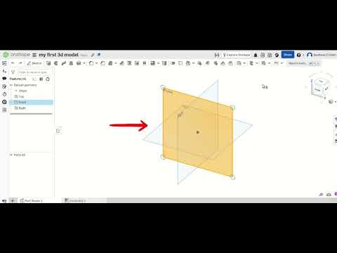
Mastering 3D CAD: The Ultimate Beginner’s Guide to Cloud-Based Onshape

Saturday, September 12, 2026

Are you ready to transform your creative concepts into tangible objects? Whether you are a hobbyist, an aspiring engineer, or a product designer, the world of digital design has never been more accessible. In this guide, we dive deep into Onshape, a revolutionary platform that is changing how we approach 3D CAD by moving the entire design process into the cloud.

Why Choose Cloud-Based Design?

Traditional design software often requires expensive hardware and complex installations. Onshape breaks these barriers by operating entirely within your web browser. This means you can access your projects from any device, anywhere in the world, without worrying about software versions or local storage. For those just starting their journey in 3D CAD, this accessibility removes the technical friction often associated with professional-grade engineering software.

Mastering the Basics of Onshape

In this second part of our beginner's series, we move beyond the interface and start building. Onshape’s power lies in its parametric modeling capabilities. This allows you to create designs based on constraints and dimensions, ensuring that every part fits perfectly within a larger assembly.

The workflow typically follows a logical progression: 1. Sketching: Creating the 2D foundation of your part. 2. Constraints: Defining relationships between lines and points to ensure stability. 3. Features: Using tools like "Extrude," "Revolve," or "Fillet" to turn those 2D sketches into 3D objects.

By mastering these fundamental steps, you gain the confidence to tackle more complex geometries and multi-part assemblies.

From Concept to Reality

The true magic of 3D CAD lies in its ability to bridge the gap between imagination and manufacturing. Once your model is complete in Onshape, it can be easily exported for 3D printing, CNC machining, or laser cutting. Because the software is cloud-based, collaboration is built into its DNA; you can share your documents with a single click, allowing for real-time feedback and teamwork.

As you continue to practice, you will find that 3D modeling is not just about drawing—it’s about problem-solving. Every sketch and feature is a step toward bringing your unique ideas to life. Stick with the process, keep experimenting with the tools, and you’ll be amazed at what you can create.

Continue Reading | ความคิดเห็น

Mastering Onshape: The Ultimate Beginner's Guide to Cloud-Based 3D CAD

Are you ready to transform your creative ideas into digital reality? Modern product design and engineering have evolved rapidly, moving away from heavy, desktop-bound software toward streamlined, cloud-based solutions. If you are just starting your design journey, learning a powerful 3D CAD platform like Onshape is one of the best ways to kickstart your skill set.

In this beginner-friendly guide, we explore how Onshape simplifies the design workflow and why browser-based modeling is revolutionizing the industry.

Why Choose Onshape for Cloud-Based Modeling?

Traditional design software often requires high-end graphics hardware, complex installation procedures, and messy file management. Onshape changes the game by operating entirely inside your web browser. This means you can access your projects from virtually any computer or tablet without worrying about software updates or lost files.

Key advantages include: - Real-Time Collaboration: Work on projects simultaneously with team members, much like Google Docs. - Automatic Version Control: Every change is saved instantly, eliminating the fear of losing progress or overwriting critical revisions. - Zero Installation: Open your browser, log in, and start modeling immediately from anywhere.

Essential Workflow in Cloud-Based 3D CAD

Mastering 3D CAD is much easier when you understand the basic design lifecycle. In Onshape, your workflow generally follows a clear, logical sequence:

  1. 2D Sketching: Begin by selecting a design plane (Top, Front, or Right) and creating 2D profiles using essential shapes like lines, circles, and rectangles.
  2. Applying Constraints: Define precise dimensions and geometric relationships so your sketch behaves predictably when adjusted.
  3. 3D Feature Creation: Convert your 2D sketch into a solid 3D object using primary tools like Extrude, Revolve, or Fillet.
  4. Assembly and Testing: Combine multiple parts together to see how they fit and move relative to one another.

Ready to Elevate Your Design Skills?

Whether you want to create custom parts for 3D printing, conceptualize consumer products, or build a foundation for an engineering career, mastering 3D CAD opens up endless possibilities. Start experimenting with simple shapes today, practice regularly, and watch your creative ideas come to life in the cloud!

Continue Reading | ความคิดเห็น

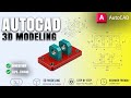
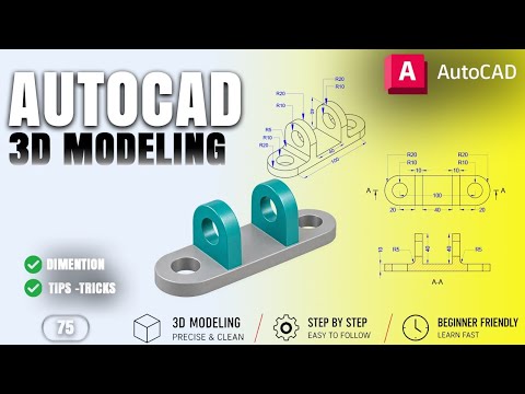
Mastering 3D CAD: How to Model a Mechanical Mounting Bracket in AutoCAD

Friday, September 11, 2026

In the evolving world of mechanical engineering, the ability to transform a 2D concept into a functional 3D model is an essential skill. One of the best ways to sharpen these skills is through practical, hands-on exercises that replicate real-world components. In this guide, we explore the process of creating a mechanical mounting bracket, a fundamental tool in the world of 3D CAD.

Starting with the Foundation: The Base Plate

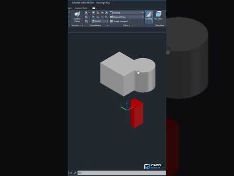
Every great mechanical model begins with a solid foundation. For this mounting bracket project, we start by constructing a rectangular base plate. In AutoCAD, this involves using primitive shapes or extruding a 2D rectangle to a specific thickness. By assigning a distinct color—such as a vibrant red—designers can easily differentiate between various components within a complex assembly. This level of visual clarity is one of the many advantages of using professional 3D CAD software for mechanical practice.

Precision Engineering and Mounting Holes

A mounting bracket is only as functional as its connectivity. The next critical step in the modeling process is the addition of four precise mounting holes located at the corners of the base. This requires careful measurement and the use of the "Subtract" command to create clean, accurate voids. This stage of the project emphasizes the importance of geometric constraints and precision, ensuring that the digital part would theoretically fit perfectly into a real-world mechanical assembly.
Why Practice Work is Essential

Whether you are a student or an aspiring engineer, consistent practice is the key to proficiency. Transitioning from basic shapes to complex mechanical parts helps users understand the workspace, the Z-axis, and the various shortcuts that speed up the design process. Utilizing 3D CAD for these practice sessions allows you to experiment with different materials, lighting, and viewing angles before moving on to more intricate industrial designs.

Conclusion

Modeling a mechanical mounting bracket is more than just a basic exercise; it is a stepping stone to mastering industrial design. By following these fundamental principles in AutoCAD, you can build a strong portfolio of mechanical parts and gain the confidence needed to tackle large-scale engineering projects. Keep practicing, keep designing, and unlock the full potential of your technical creativity!

Continue Reading | ความคิดเห็น

From 2D Drafting to 3D CAD: The Professional’s Guide to Modern Modeling

Thursday, September 10, 2026

In the competitive world of design and engineering, the shift from traditional 2D drafting to a robust 3D CAD environment is no longer just an optional skill—it is a business necessity. While AutoCAD has long been the gold standard for precision floor plans and technical schematics, upgrading your workflow to three dimensions can fundamentally change how you communicate ideas and deliver value to your clients.

The Business Case for Dimensional Depth

The primary advantage of moving beyond flat lines is the ability to visualize spatial relationships with absolute clarity. When you utilize 3D CAD software, you are essentially building a virtual prototype rather than just drawing a representation of one. This allows for early-stage clash detection, more accurate material estimation, and significantly more persuasive client presentations. Instead of asking a stakeholder to imagine the scale of a project through a flat blueprint, you can offer them a realistic digital walkthrough.

Boosting Precision and Efficiency

Transitioning to 3D doesn't mean discarding your 2D roots. In fact, professional-grade modeling often starts with a 2D sketch or foundation. However, the true power lies in the automation that three-dimensional environments provide. In a modern workflow, updates made to a model can automatically propagate through all associated elevations, sections, and schedules. This drastically reduces the manual labor associated with revisions and ensures that your documentation remains consistent across the board. By spending less time on manual updates, your team can focus more on design innovation.

Bridging the Professional Gap

Making the upgrade requires a strategic shift in mindset. You are moving from thinking in lines and arcs to thinking in volumes and surfaces. By integrating 3D CAD into your daily professional practice, you position yourself as a forward-thinking expert capable of handling the complexities of modern architecture, manufacturing, and engineering projects. While the learning curve may seem steep initially, the long-term return on investment in project clarity and delivery speed is undeniable. Now is the time to transform your flat drawings into immersive, functional models that set your business apart.

Continue Reading | ความคิดเห็น

Mastering Mechanical Design: A Step-by-Step Guide to 3D CAD Modeling for Mounting Brackets

Wednesday, September 9, 2026

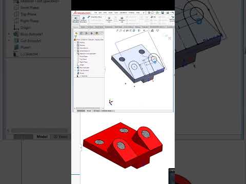
In the rapidly evolving world of mechanical engineering, the ability to transform a conceptual 2D sketch into a functional, three-dimensional model is a critical skill. Whether you are a student or a seasoned professional, mastering 3D CAD software is essential for staying competitive in the design industry. In this guide, we will explore the foundational techniques used to create a mechanical mounting bracket, a common component found in various industrial applications.

Understanding the Component: The Mounting Bracket

The project focuses on a 3D mechanical mounting bracket, a vital piece of hardware used to secure components in place. The design features a long, rounded rectangular base plate, which provides stability and a solid surface for attachment. This specific model serves as an excellent practice piece because it combines basic geometric shapes with precise technical requirements.

By focusing on the base plate first, designers can learn how to manage fillets (rounded corners) and ensure that the proportions are accurate before moving on to more complex features. Precision is the cornerstone of mechanical design, and practicing with these foundational shapes builds the necessary muscle memory for larger projects.

The 3D CAD Modeling Workflow

To create this bracket, the modeling process typically begins with a 2D profile. Using 3D CAD tools, the designer draws the footprint of the bracket, ensuring that the dimensions for the length and width are exact. Once the 2D sketch is finalized, the "Extrude" command is used to give the bracket its thickness.

Key steps in this workflow include: 1. Sketching the Base: Creating the rectangular profile with rounded ends. 2. Adding Mounting Holes: Positioning two mounting holes accurately to ensure the bracket can be bolted to a surface. 3. Applying 3D Transforms: Using subtraction or union tools to finalize the mechanical structure.

Why Practice Matters

Mechanical practice work, such as modeling this mounting bracket, is about more than just learning software buttons; it is about understanding spatial relationships and manufacturing constraints. Utilizing 3D CAD allows you to visualize potential interference issues and material thickness before a single part is ever manufactured.

As you continue your journey in AutoCAD and 3D modeling, remember that consistency is key. Exercises like these prepare you for complex assemblies, helping you bridge the gap between a simple idea and a professional-grade mechanical component.

Continue Reading | ความคิดเห็น

Master AutoCAD: A Step-by-Step Guide to 3D CAD Modeling

Transitioning from traditional 2D drafting to the dynamic world of digital design can seem intimidating, but learning 3D CAD is one of the most rewarding skills for students, engineers, and designers alike. Whether you are completing a practical class assignment or building a professional design portfolio, creating three-dimensional figures is an essential step in modern CAD mastery.

In this guide, we will break down the core process of transforming simple concepts into fully realized solid models using AutoCAD.

Setting Up Your 3D Workspace

Before creating any object, you need to prepare your design environment. Switch your workspace from the standard "2D Drafting & Annotation" mode to "3D Modeling." This change gives you direct access to powerful modeling tools, such as solid primitives, extrusion features, and Boolean commands.

When working in a 3D CAD environment, dynamic navigation is critical. Learn to use the ViewCube and Navigation Bar to orbit around your workspace smoothly. Viewing your project from multiple angles ensures accurate alignment along the X, Y, and Z axes.

Key Steps to Construct a 3D Figure

Building a complex 3D figure typically follows a simple, structured workflow:

  1. Draw the 2D Outline: Start by creating a accurate 2D base profile using closed polylines. A clean 2D sketch forms the foundation of any solid model.
  2. Extrude or Presspull: Convert your flat sketch into a solid shape by giving it height. Use the Extrude or Presspull tool to extend the geometry along the Z-axis.
  3. Refine with Boolean Operations: Combine different shapes using the Union tool, or create cutouts, holes, and slots using the Subtract command.

Tips for an Efficient Workflow

To keep your design process smooth and organized, implement these quick tips: - Organize with Layers: Keep your original 2D construction lines, solid models, and annotations on separate layers. - Toggle Visual Styles: Switch between "2D Wireframe" for precise snapping and "Shaded with Edges" to preview your final 3D figure. - Practice with Hands-On Tasks: The fastest way to learn is by following practical tutorials and recreating real-world mechanical parts or geometric shapes.

By mastering these fundamental techniques, you will be well on your way to creating accurate, professional-grade models in 3D CAD. Open your software, try out these steps, and bring your designs to life today!

Continue Reading | ความคิดเห็น

Elevate Your Design Workflow with Essential 3D CAD Tips in SolidWorks

Saturday, September 5, 2026

In today's fast-paced engineering and design industries, mastering digital modeling tools is essential for bringing creative ideas to life. Whether you are an automotive engineer, an industrial designer, or a digital artist, modern product design relies heavily on advanced 3D CAD software to ensure precision, structural integrity, and efficiency.

Among the various modeling tools available today, SolidWorks remains a leading industry standard. However, simply knowing the basic commands isn't enough to build complex, production-ready models efficiently. To truly excel, you need to adopt smart workflows and optimized modeling strategies.

Streamlining Your Modeling Process

Creating clean, editable, and robust models requires a solid foundation. Here are a few key practices to optimize your design routines:

  • Keep Sketches Simple and Fully Defined: Avoid creating overly complicated sketches with dozens of geometric entities in a single feature. Break complex shapes down into smaller, manageable features. Always ensure your sketches are fully defined to prevent accidental shifts in geometry.
  • Utilize Parametric Intent: Design with the end goal in mind. Use parametric relations and smart dimensions so that if a design change is needed later, your model adapts seamlessly without breaking the feature tree.
  • Master Keyboard Shortcuts: Customizing your user interface and utilizing hotkeys for frequently used commands—such as extrude, cut, and smart dimension—can drastically reduce your overall design time.

Elevating Your Technical Skills

Integrating these techniques into your daily 3D CAD workflow will not only speed up your modeling process but also make your design files much easier for team members to modify and review. Clean design trees and efficient feature management are the hallmarks of a professional designer.

Whether you are working on automotive components, consumer electronics, or intricate mechanical assemblies, continuously refining your 3D CAD skills will set you apart in the competitive world of design engineering. Start applying these actionable tips to your next project and watch your productivity soar!

Continue Reading | ความคิดเห็น

Mastering SolidWorks: Essential 3D CAD Modeling Tips and Best Practices

Friday, September 4, 2026

Whether you are an engineering student, an industrial designer, or an automotive enthusiast, mastering 3D CAD tools like SolidWorks is essential for bringing your complex visual ideas to life. SolidWorks remains one of the most powerful software packages in the modern design industry, but creating detailed models efficiently requires more than just knowing basic commands—it demands smart techniques and optimized workflows.

Why SolidWorks is Essential for Modern Design

SolidWorks has transformed how professionals approach product development and mechanical engineering. Utilizing advanced 3D CAD software allows designers to construct highly accurate parametric models that can be analyzed, modified, and manufactured with precision. From high-performance automotive components to intricate artistic structures, the platform provides the ideal sandbox to test concepts virtually long before physical production begins.

Top Tips to Elevate Your SolidWorks Workflow

To streamline your modeling process and reduce overall design time, consider integrating these fundamental practices into your daily routine:

  • Master Fully Defined Sketches: Always ensure your 2D sketches are fully defined using precise dimensions and geometric relations. Unconstrained sketches lead to unpredictable errors when modifying geometry downstream.
  • Keep the Feature Tree Organized: Name your features logically and group related operations into folders. A clean FeatureManager tree makes team collaboration seamless and renders future edits hassle-free.
  • Leverage Custom Keyboard Shortcuts: Map your most frequently used commands—such as Extrude, Revolve, and Smart Dimension—to simple hotkeys to dramatically boost your modeling speed.
  • Design with Intent: Plan your geometry before placing the first sketch line. Consider how the part might need to adapt in future iterations and construct your feature relationships accordingly.

Transforming Concepts into Reality

By incorporating these essential habits into your design process, you can maximize your productivity and unlock the full potential of 3D CAD modeling. Whether you are crafting precise automotive assemblies or exploring creative 3D art, consistent practice paired with smart modeling techniques will elevate the quality of your work. Start applying these core principles today to take your SolidWorks projects to the next level!

Continue Reading | ความคิดเห็น

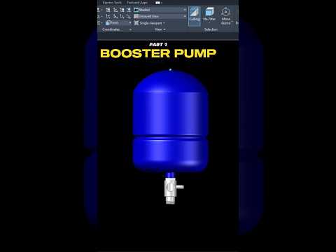
Mastering Mechanical Design: A Step-by-Step Guide to 3D CAD Booster Pump Assembly

Mechanical engineering and industrial design have been revolutionized by the power of digital modeling. If you have ever wondered how complex machinery, such as a high-performance booster pump, is constructed from the ground up, you are in the right place. In this first installment of our series, we dive deep into the technical process of building a booster pump assembly component by component.

The Foundation of Industrial Modeling

A booster pump is a vital piece of equipment used to increase the pressure of fluids in various systems, from residential water lines to massive industrial cooling towers. Modeling such a device requires a high level of precision and a systematic approach. By utilizing 3D CAD software, designers can create a digital twin of the pump, allowing them to test fitments, check tolerances, and visualize the final product before a single piece of metal is ever cast.

Precision Component Creation

The assembly process begins with the individual parts. In Part 1 of our guide, we focus on the foundational elements, such as the pump housing and the base plate. Using AutoCAD’s robust toolset, we transition from simple 2D sketches into complex three-dimensional geometries. This stage involves utilizing commands like Extrude, Revolve, and Sweep to give volume to our technical drawings.

The beauty of working within a 3D CAD environment is the ability to maintain absolute accuracy. Whether you are defining the diameter of a flange or the curvature of an impeller blade, the software ensures that every measurement is mathematically sound. This meticulous attention to detail is what separates a hobbyist from a professional designer.

Why Mastering Assembly Matters

Understanding how to assemble parts is just as important as knowing how to draw them. In this series, we don't just look at parts in isolation; we look at how they interact. We explore the constraints and alignments necessary to ensure that the motor, shaft, and housing align perfectly.

Developing these skills in 3D CAD is essential for anyone looking to excel in the fields of manufacturing or architecture. By following along with this booster pump project, you will gain a practical understanding of spatial relationships and mechanical constraints.

Stay tuned for the next part of this series, where we will continue to add complexity to our assembly, moving one step closer to a fully functional mechanical model. Whether you are a student or a seasoned pro, there is always something new to learn in the world of 3D design.

Continue Reading | ความคิดเห็น

2D to 3D Made Easy: Mastering the AutoCAD PRESSPULL Command for 3D CAD

In the fast-paced world of digital design, the ability to transition quickly from a flat sketch to a complex model is a vital skill. If you are looking to excel in 3D CAD, understanding the tools that bridge the gap between 2D drafting and 3D visualization is essential. One of the most powerful and time-saving features available to designers today is the AutoCAD PRESSPULL command.

What Makes PRESSPULL So Powerful?

While many beginners rely solely on the "Extrude" command, the PRESSPULL tool offers a much more dynamic and versatile approach. It allows you to select a bounded area—even if it is not a closed polyline—and instantly pull it into the third dimension. This versatility makes it a cornerstone for anyone looking to streamline their workflow in 3D CAD.

Beyond just adding volume, PRESSPULL is dual-purpose. It can be used to subtract material by pushing a shape into an existing solid, making it an incredibly efficient tool for creating holes, slots, or recessed features without needing complex Boolean operations.

Step-by-Step: From 2D to 3D in Seconds

Mastering this command is straightforward. Follow these steps to speed up your modeling process: 1. Initialize the Command: Type PRESSPULL in the command line or select the icon from the Modeling tab. 2. Select the Area: Hover your cursor over the 2D shape or a bounded internal area. AutoCAD will automatically highlight the detected space. 3. Define the Height: Click and drag your mouse upward to add height, or move it inward to cut through a solid. 4. Precision Entry: For exact engineering specifications, simply type in the desired numerical value and hit Enter.

Why It Changes Your Workflow

Efficiency is the ultimate goal when working on complex 3D CAD projects. The PRESSPULL command eliminates the tedious step of joining individual lines into regions or polylines before they can be transformed. It intelligently recognizes internal boundaries, allowing you to create architectural walls with window cutouts or mechanical parts with pre-drilled holes in just a few clicks.

By incorporating this simple shortcut into your daily routine, you can significantly reduce your modeling time and focus more on the creative aspects of your design. Whether you are a beginner or a seasoned professional, the PRESSPULL command is a must-know feature that makes 3D modeling feel like second nature.

Continue Reading | ความคิดเห็น

Plasticity Review: Is This the Best 3D CAD Tool for Artists and 3D Printing?

Thursday, September 3, 2026

For years, 3D printing enthusiasts and digital artists faced a difficult choice when picking modeling software: endure the steep, technical learning curve of traditional engineering programs, or use artistic sculptors like Blender that often struggle with exact dimensions and solid geometry. Enter Plasticity—a hotkey-driven, direct-modeling tool designed specifically to bridge this gap. But can it truly streamline your workflow for physical creations?

Rethinking Direct Modeling for Designers

Unlike traditional parametric software that relies heavily on complex feature trees and rigid constraints, Plasticity focuses on a fast, direct-modeling workflow. It borrows the intuitive hotkey navigation popular in digital art tools, making it feel second nature to artists and sculptors.

By prioritizing direct face pushing, pulling, and curve manipulation, it removes the friction between creative ideation and technical execution. This unique design philosophy makes 3D CAD accessible to creative minds who previously shied away from engineering-heavy interfaces.

Precision Meets Artistic Freedom

One of the biggest hurdles when preparing models for 3D printing is ensuring clean, solid geometry. Traditional mesh modeling software can easily produce non-manifold edges and clipping faces that result in failed slices. Plasticity solves this by operating as a true NURBS modeling engine under the hood.

This means you get the aesthetic freedom of polygonal modeling combined with the dimensional accuracy of modern 3D CAD software. Creating smooth fillets, sharp chamfers, and precise boolean cuts is remarkably fluid, yielding high-quality STL and STEP files that are instantly ready for your 3D printer.

The Verdict: Should You Make the Switch?

If your design process relies heavily on parametric history trees—where changing an early sketch dimension needs to automatically update a complex mechanical assembly—traditional software may still be necessary. However, if you are an artist, concept designer, or hobbyist who wants to turn creative ideas into physical prints quickly, Plasticity is a game-changer.

It strikes a rare balance between speed, usability, and technical precision, proving that 3D CAD doesn't have to feel like drafting software—it can feel as natural and expressive as digital sketching.

3D CAD
Continue Reading | ความคิดเห็น

Master Interference Checking in AutoCAD: A Guide to Flawless 3D CAD Modeling

Wednesday, September 2, 2026

When working on complex engineering or architectural designs, precision is everything. A single overlapping component can lead to costly errors during fabrication or construction. If you rely on AutoCAD for your 3D CAD projects, detecting spatial conflicts early is essential to maintaining model accuracy. Fortunately, AutoCAD features a powerful built-in tool specifically designed for clash detection: the INTERFERE command.

What is the INTERFERE Command in AutoCAD?

The INTERFERE command allows users to compare sets of 3D solid objects to check if they overlap or occupy the same physical space. Unlike standard Boolean operations such as SUBTRACT or UNION, which permanently alter your geometry, INTERFERE highlights overlapping volumes by generating temporary 3D solids. This lets you inspect and resolve design collisions without modifying your original components.

Step-by-Step: How to Perform an Interference Check

Running an interference check in AutoCAD is straightforward and fast:

  1. Activate the Command: Type INTERFERE into the command line and press Enter.
  2. Select First Object Set: Select the first group of 3D solids you want to check, then press Enter.
  3. Select Second Object Set: Choose the second set of 3D solids to compare against the first (or press Enter again to check for interferences among the first set alone).
  4. Review Results: AutoCAD opens the Interference Checking dialog box and temporarily highlights any overlapping geometry in red.
  5. Manage Clashes: Cycle through each interference point, zoom into specific conflict areas, and choose whether to delete or keep the generated interference solids for reference.

Why Clash Detection Matters for Your Workflow

Integrating regular clash detection into your 3D CAD workflow offers several key advantages:

  • Prevents Manufacturing Errors: Spotting physical overlaps early ensures components fit together seamlessly during actual assembly.
  • Saves Time and Money: Identifying errors during drafting takes seconds, whereas fixing mistakes on the shop floor or construction site is expensive and time-consuming.
  • Improves Model Quality: Clean geometry yields accurate mass property calculations, faster rendering, and seamless exports.

Mastering the INTERFERE command is one of the easiest ways to elevate the quality of your 3D CAD designs. Incorporate this quick check into your routine to ensure your 3D models are accurate, professional, and conflict-free!

3D CAD
Continue Reading | ความคิดเห็น

Top SolidWorks Tips to Elevate Your 3D CAD Modeling Skills

Monday, August 31, 2026

Whether you are a seasoned mechanical engineer or a passionate beginner entering the digital design world, mastering SolidWorks is crucial for producing efficient, high-quality models. As industry standards continue to evolve, staying updated with quick tips and tricks can dramatically speed up your workflow and enhance your technical output.

Why SolidWorks Leads the 3D CAD Industry

SolidWorks remains one of the most powerful and intuitive software solutions used globally across automotive, aerospace, and product design sectors. Utilizing modern 3D CAD tools allows designers to transform complex concepts into precise, functional models with unmatched parametric accuracy. By leveraging advanced assembly techniques, surface modeling, and structural simulations, you can bring even the most intricate engineering visions to life seamlessly.

Essential Tips for Efficient 3D Modeling

To get the most out of your parametric design process, consider integrating these practical habits into your daily workflow:

  1. Optimize Your Sketching: Always fully define your sketches using smart dimensions and geometric relations. This prevents unexpected errors later in the design tree when making parametric modifications.
  2. Master Shortcut Keys: Customize your 'S' key menu and mouse gestures. Minimizing the time spent searching for features on the ribbon toolbar will double your modeling speed over time.
  3. Keep Feature Trees Clean: Name your key features and group related operations into logical folders. A well-organized feature manager tree makes team collaboration smooth and simplifies future revisions.
  4. Utilize Standard Configurations: Take advantage of SolidWorks configurations to create multiple variations of a single part or assembly within one file, saving both time and storage space.

Elevating Your Design Workflow

Mastering 3D CAD software is not just about learning which buttons to press; it is about adopting a structured design mindset. By practicing efficient modeling strategies and continually exploring quick tips, you can significantly reduce design cycle times, minimize manufacturing errors, and create realistic visual prototypes that stand out.

Start implementing these essential SolidWorks tips today, and watch your 3D CAD design efficiency soar to new heights!

3D CAD
Continue Reading | ความคิดเห็น

Master SolidWorks: Essential 3D CAD Modeling Tips for Beginners and Pros

SolidWorks remains one of the most powerful and widely used tools in modern engineering and product design. Whether you are an aspiring maker or an experienced mechanical engineer, mastering 3D CAD software is essential for bringing creative concepts into precise, functional models. From basic geometric sketches to complex parametric assemblies, honing your workflow saves valuable development time while boosting overall project accuracy.

Key SolidWorks Techniques for Speed and Precision

Creating clean, scalable models requires more than just knowing where tools are located—it requires a strong understanding of design intent. Here are fundamental practices to streamline your drafting process:

  • Fully Define Your Sketches: Always ensure your 2D profiles are fully constrained using smart dimensions and geometric relations (such as concentric, parallel, or equal). This prevents accidental shifts later in the design tree.
  • Maintain an Organized Feature Tree: Keep your feature manager organized. Rename key features, group related operations, and avoid unnecessary extrusions or cuts to make future edits hassle-free.
  • Leverage Shortcuts and Hotkeys: Customizing mouse gestures and keyboard shortcuts for frequently used tools like Extrude, Revolve, and Smart Dimension will dramatically speed up your execution.

Elevating Your Projects with Modern 3D CAD Workflows

As you advance beyond basic shapes, adopting structured 3D CAD workflows will significantly improve the quality of your output. Utilizing tools such as global variables and equations allows your models to adapt dynamically whenever specifications change. Furthermore, paying attention to surface fillets and visual materials helps convert basic technical parts into realistic visual assets suitable for presentations.

Consistently practicing these tips ensures your designs are not only visually impressive but also optimized for prototyping, 3D printing, and manufacturing. Investing time in mastering modern 3D CAD capabilities is the best way to sharpen your skills and stand out in the competitive design industry.

3D CAD
Continue Reading | ความคิดเห็น

Master Bevel Shaft Design in CATIA V5: Essential 3D CAD Modeling Techniques

Sunday, August 30, 2026

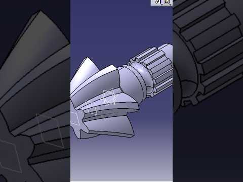
Precision engineering begins with accurate digital modeling, and mastering complex mechanical components is essential for any modern designer. Among these components, bevel shafts play a vital role in transmitting power across intersecting axes in various machinery. Learning how to create a detailed bevel shaft using robust 3D CAD software like CATIA V5 is an invaluable skill for mechanical engineers and industrial designers alike.

Understanding the Fundamentals of Bevel Shaft Design

A bevel shaft requires precise angular dimensions, concentric profiles, and exact alignment to ensure smooth power transmission in real-world applications. When building this part in CATIA V5's Part Design workbench, designers must focus on maintaining parametric integrity. By establishing clear geometric constraints during the initial sketching phase, you ensure that any future design modifications can be updated seamlessly.

Essential Steps in the 3D CAD Modeling Workflow

Creating a professional bevel shaft model involves a structured approach within CATIA V5:

  • 2D Sketching & Profile Definition: Begin by creating a fully constrained 2D sketch representing the cross-section of the shaft, paying careful attention to bevel angles and shoulder steps.
  • Shaft (Revolve) Operation: Use the sketch to generate the main solid body by revolving the profile around the central reference axis.
  • Tooth & Geometry Creation: Position custom planes to sketch gear teeth profiles or specialized keyways required for torque transfer.
  • Pocket and Circular Pattern: Execute pocket cuts for gear features and utilize the Circular Pattern tool to replicate the feature uniformly around the circumference.
  • Detailing & Finishing: Apply functional chamfers, edge fillets, and thread definitions to finalize the component.

Adhering to this systematic 3D CAD process reduces design errors and ensures the part is ready for digital assembly or stress analysis.

Elevate Your Mechanical Engineering Skills

CATIA V5 remains an industry standard across aerospace, automotive, and manufacturing sectors due to its unmatched surface and solid modeling capabilities. Mastering essential 3D CAD workflows like bevel shaft modeling empowers you to build complex, production-ready components and accelerates your professional growth in modern CAD design.

3D CAD
Continue Reading | ความคิดเห็น

Popular Posts Today

 
Support : 3Dcadbrowser | Grabcad | 3Dcontentcentral | D | E | F | G
Copyright © 2028. Engineering 3DCad Appication - All Rights Reserved