Cad 3D Category

Showing posts with label 3D CAD. Show all posts

Mastering Soft Body Physics: A Deep Dive into 3D Modeling and Simulation

Friday, November 6, 2026

Have you ever wondered how digital objects squash, stretch, and bounce so realistically in modern animations? Physics simulations have revolutionized digital art, allowing creators to craft hyper-realistic or delightfully satisfying visual experiences. One of the most fascinating areas to explore within 3D modeling is soft body dynamics—specifically how extreme parameter settings transform simple shape collisions.

What is Soft Body Simulation?

In popular software suites like Blender and Cinema 4D, soft body simulation mimics real-world deformable materials. Instead of treating shapes like solid, unyielding blocks, soft body physics enables meshes to flex, compress, and react dynamically upon impact.

When running a collision experiment—such as a cone interacting with a torus shape—adjusting values from 0% to 100% dramatically alters the physical behavior:

  • 0% Stiffness (Maximum Flexibility): The object behaves like liquid jelly or loose rubber, deforming instantly and squishy upon contact.
  • 100% Stiffness (Maximum Rigidity): The shape maintains its structural form, behaving more like firm foam or solid rubber while absorbing minimal shock.

Why Parameter Testing Matters in 3D Modeling

Understanding these extreme boundary values is crucial for artists aiming to refine their technical toolkit. By testing 0% versus 100% configuration values, creators learn how to fine-tune elasticity, mass, and damping to hit the exact aesthetic sweet spot. Modern 3D modeling relies heavily on these physics engines to create convincing materials ranging from soft clothing and organic tissue to high-tech rubber components.

Beyond the technical benefits, these soft body experiments are undeniably hypnotic to watch. The visual contrast between complete structural collapse and rigid resilience makes for engaging, satisfying video content that captures audience attention.

Elevating Your Animations with Physics Dynamics

Whether you work with Blender, C4D, or Maya, experimenting with soft body interactions is one of the quickest ways to bring static geometric primitives to life. By combining simple shapes like cones and toruses with realistic force settings, contemporary 3D modeling allows digital artists to convert simple mesh collisions into captivating work. Open up your simulation panel today and start experimenting with soft body parameters to see what satisfying animations you can create!

Continue Reading | ความคิดเห็น

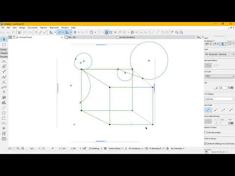
Mastering ArchiCAD 3D: Powerful Tips to Create and Modify Architectural Drawings

Whether you are an aspiring architect, an experienced draftsman, or a BIM enthusiast, mastering digital design tools is essential for modern architectural workflows. Among the leading Building Information Modeling (BIM) software, ArchiCAD 3D stands out as a flexible, powerful solution that seamlessly connects 2D drafting with stunning three-dimensional visualization.

In this practical guide, we will explore key tips and techniques to help you effectively create and modify architectural drawings, boosting both your design precision and modeling speed.

Setting Up and Creating Drawings Efficiently

Starting a project with a clean workflow saves hours of rework later. When creating new drawings, begin by establishing precise grid systems and story settings. Utilizing parametric tools—such as smart walls, slabs, doors, and windows—allows you to build an intelligent design right from the first click.

Instead of viewing 2D drafting and 3D modeling as separate steps, leverage the full capabilities of ArchiCAD 3D. Every wall or object you place in the 2D floor plan view automatically generates corresponding geometry in the 3D window, ensuring complete model accuracy and consistency.

Modifying and Fine-Tuning Your Design

Architecture is an iterative process, and modifying your drawings swiftly is just as important as creating them. ArchiCAD offers robust editing tools designed to keep your work dynamic:

  • Pet Palette Shortcuts: Master the context-sensitive Pet Palette to offset, stretch, curve, or rotate elements on the fly.
  • Trim and Split Tools: Keep geometry clean by using quick keyboard shortcuts to trim unwanted lines or split complex shapes.
  • Parameter Transfer: Use the Eyedropper and Syringe tools (Alt and Ctrl/Cmd + Alt) to instantly copy and inject properties from one element to another across your layout.

Bridging 2D Drafting and 3D Visualization

One of the key advantages of working within ArchiCAD 3D is the ability to inspect your design instantly in a realistic spatial environment. Switching back and forth between 2D floor plans and 3D views helps you spot spatial errors, verify material alignments, and make modifications directly in the 3D workspace.

By integrating both 2D drafting tips and 3D editing techniques into your daily routine, you will dramatically streamline your architectural documentation process and deliver professional results in less time.

Conclusion

Building an efficient modeling workflow requires practice, but mastering basic creation and modification features will quickly elevate your architectural projects. Apply these essential tips to your next project and unlock the full potential of your design workspace!
Continue Reading | ความคิดเห็น

Reacting to My 2015 Demo Reel: My Evolution with Cinema 4D 3D and Video Editing

Thursday, November 5, 2026

Every professional video editor and motion designer has to start somewhere. Looking back at your early work can be a humbling experience—partly cringe-inducing, but mostly inspiring. Recently, I decided to open the vault and react to my video editing demo reel from 2015. It is a raw, unfiltered snapshot of where my post-production journey truly began over a decade ago.

The Raw Reality of Early Video Editing

Back in 2015, I thought my cuts were seamless, my color grading was revolutionary, and my pace was unmatched. Rewatching that reel today, however, tells a very different story. The timeline was filled with overly dramatic transitions, gratuitous lens flares, and slightly awkward audio cuts.

Yet, beneath those rookie choices was a genuine passion for visual storytelling. Examining early projects reminds us that creative mastery doesn't happen overnight. It takes years of trial, error, and constant refinement to build a solid aesthetic sense and smooth editing workflow.

Experimenting with Cinema 4D 3D and Early Visual Effects

One of the most eye-opening parts of reviewing old footage is seeing early attempts at motion graphics and visual effects. Even back then, I was eager to elevate my edits by integrating three-dimensional elements using Cinema 4D 3D.

Looking at those old renders today, the lighting, textures, and camera moves look primitive compared to modern standards. However, those early experiments with Cinema 4D 3D laid the essential foundation for my current skillset. Learning how to manipulate lighting, keyframe animations, and integrate renders into live-action footage early on was crucial for my long-term career growth.

Key Takeaways for Aspiring Editors and Creators

If you are currently looking at your own work and feeling discouraged, keep these points in mind:

  • Embrace the Cringe: Feeling embarrassed by your old work is actually a good sign. It proves that your creative eye has developed and your standard for quality has risen.
  • Build Strong Foundations: Experimenting with tools like Cinema 4D 3D early in your journey gives you a massive edge as software and industry demands evolve.
  • Track Your Progress: Keep your old demo reels and project files saved. They serve as valuable milestones showing how much your technical abilities have grown over time.

Final Thoughts

Never be afraid to put out work that isn't perfect. Every flawed cut, unrefined color grade, and basic 3D render is a necessary stepping stone toward professional skill. Keep creating, keep experimenting, and celebrate how far you’ve come!
Continue Reading | ความคิดเห็น

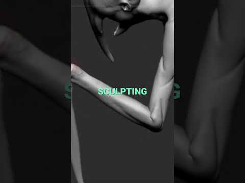
Unlock Creative Control: Mastering Tapering and Pinching in ZBrush 3D

Whether you are a seasoned digital artist or just beginning your journey into character creation, refining forms and sharp details is key to crafting compelling models. In the world of ZBrush 3D, mastering control over your mesh can turn a basic sculpt into an extraordinary masterpiece. Two of the most versatile yet fundamental techniques in any artist's workflow are tapering and pinching.

The Power of Pinching: Crisp Edges and Fine Details

When working on organic sculpts or intricate hard-surface models, soft brushes can sometimes leave your mesh feeling spongy or ill-defined. This is where pinching becomes indispensable. By drawing geometry closer together along a line, pinching allows you to sharpen soft creases, define monster wrinkles, and crisp up razor-sharp edges on armor or creature features.

A subtle touch goes a long way. Just a small pinch here and there can instantly transform a flat, lifeless surface into a focal point rich with detail. Use it strategically along your mesh flow to accentuate facial features, muscle seams, and skin folds.

Silhouette Control: Mastering Tapering Techniques

While pinching refines micro-details, tapering gives you macro control over proportions and silhouette. Utilizing tapering deformers and brushes in ZBrush 3D enables artists to smoothly transition broad, heavy bases into elegant, pointed tips.

Tapering is essential for creature design. It allows you to build believable tentacles, curved horns, stylized hair, and menacing claws effortlessly. By dynamically scaling geometry along an axis, you ensure smooth, natural transitions that maintain visual weight and realistic flow throughout your character.

Combining Pinch and Taper for Dynamic Designs

The real magic happens when you combine both methods. Start by using tapering to establish the overarching silhouette and proportional rhythm of your sculpt. Once the overall silhouette is locked in, pass over the key areas with a pinch brush to tighten the edges, accentuate directional lines, and add structural definition.

By integrating these core techniques into your daily workflow, you will achieve cleaner topology, sharper forms, and a faster sculpting speed. Fire up ZBrush 3D today, start experimenting with tapering and pinching, and bring your digital creatures to the next level!

Continue Reading | ความคิดเห็น

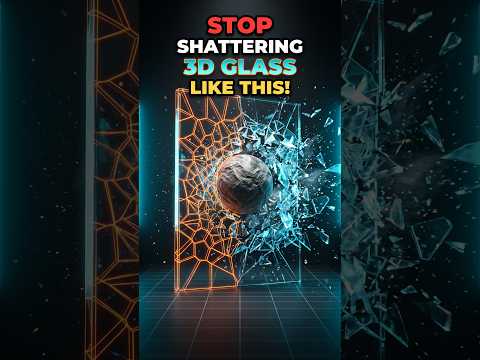
Master Realistic Glass Destruction: The Ultimate Blender 3D Tutorial

Have you ever tried to create a shattering glass effect, only to find that it looks more like falling blocks than actual shards? You aren’t alone. Achieving high-quality, believable destruction is one of the most sought-after skills in the world of CGI. When it comes to creating high-end visual effects, mastering Blender 3D requires moving beyond basic presets and understanding how materials actually break in the real world.

The Problem with Basic Shattering

Most beginners make the mistake of creating uniform pieces that lack the chaotic variety of real glass. Real glass doesn't just split into equal cubes; it splinters into jagged shards, tiny slivers, and larger chunks based on the point of impact. If your simulation looks "off," it’s likely because the fracture pattern is too predictable. To fix this, we need to leverage the right tools and physics settings.

Step 1: Harnessing the Power of Cell Fracture

The secret to realistic destruction lies in the Cell Fracture add-on. Before you start, ensure the add-on is enabled in your preferences. Once active, you can take your mesh and apply the fracture.

The key tip here is to use a "Particle System" or "Annotation Tool" to define where the impact happens. By concentrating the fracture points around the area where the object hits the glass, you create a much more realistic radial pattern. Within the Cell Fracture settings, increasing the "Noise" value is essential—it ensures that the edges of your shards are jagged and irregular rather than perfectly straight.

Step 2: Refining Physics with Rigid Bodies

Once your glass is fractured, you need to tell the software how those pieces should move. This is where the physics engine in Blender 3D shines. By assigning a Rigid Body to your shards, you can simulate gravity, friction, and collision.

Pro-Tip: Use the "Calculate Mass" function to ensure the shards have a realistic weight. Light glass shards should behave differently than heavy concrete chunks. Additionally, don't forget to set your "Collision Margin" to a very low number to avoid shards "exploding" outward the moment the animation starts.

Final Touches for Realism

To truly sell the effect, add a touch of "Slow Motion" by adjusting the scene's time scale, and ensure your glass material has a high transmissive value with a touch of roughness on the broken edges.

Elevate your Blender 3D projects today by moving away from generic shattering and embracing the precision of Cell Fracture. With these techniques, your destruction sequences will go from "amateur" to "cinematic" in no time!

Continue Reading | ความคิดเห็น

Master the SketchUp 3D Camera Toolbar: A Complete Beginner's Guide

Wednesday, November 4, 2026

Navigating your workspace efficiently is one of the most critical skills to master when working in digital design. If you are just starting your journey with SketchUp 3D, getting comfortable with the Camera Toolbar is your first step toward effortless modeling and presentation.

In this guide, we will break down the fundamental camera tools every beginner needs to know to navigate their models like a pro.

Essential Tools in the Camera Toolbar

The Camera Toolbar provides direct control over your viewport. Understanding these primary tools will significantly improve your design speed:

  • Orbit Tool: Allows you to rotate your view around the model in any direction. This is essential for inspecting your work from different angles.
  • Pan Tool: Moves your screen horizontally or vertically without changing the view angle or zooming level.
  • Zoom Tool: Lets you move closer to or further away from your object, giving you precise control over detail work.
  • Zoom Window: Allows you to select a specific rectangular area on your canvas to magnify instantly.
  • Zoom Extents: A life-saving feature that instantly centers and fits your entire model within the viewport—perfect if you ever get lost in space!

Perspective vs. Walkthrough Views

Beyond basic viewport control, the Camera Toolbar features specialized controls designed to help you showcase your SketchUp 3D projects realistically.

  • Position Camera: Sets your view at a specific eye-level height, giving you a realistic human perspective of your interior or exterior spaces.
  • Look Around: Rotates the camera from a fixed point, simulating standing in place and looking around a room.
  • Walk Tool: Allows you to maneuver through your design as if you were walking inside it, which is ideal for client walkthroughs.

You can also easily switch between Perspective view (for realistic presentation) and Parallel Projection (for 2D blueprints and elevation drawings) via the Camera menu.

Quick Navigation Tips for Beginners

To maximize your efficiency in SketchUp 3D, try using your mouse shortcuts alongside the Camera Toolbar: 1. Middle Mouse Button (Scroll Wheel): Press and hold to Orbit automatically without selecting the tool from the menu. 2. Shift + Middle Mouse Button: Hold Shift while pressing the scroll wheel to instantly Pan across your screen.

By combining toolbar controls with mouse shortcuts, you will streamline your workflow and navigate complex 3D environments with confidence. Take some time to practice these essential camera tools today, and watch your modeling efficiency skyrocket!

Continue Reading | ความคิดเห็น

Streamlining CAD Workflows: Bill-Builder Walkthrough and SolidWorks 3D Integration

Designing complex engineering projects requires a smooth, stress-free workflow from concept to completion. If you are exploring the Bill-Builder environment for the first time, establishing a clear process is essential for maintaining model accuracy and design speed. In this guided walkthrough, we will explore how to navigate regions, verify cross-sections, and achieve a seamless handoff to your primary design software.

Navigating the Bill-Builder Environment

Starting out in Bill-Builder begins with a calm, methodical inspection of your model. Users can easily review specific regions, inspect cross-sections, and make necessary adjustments without disrupting the overall design hierarchy. The platform allows you to save your progress at any stage and reopen files effortlessly, ensuring that your data remains intact and secure throughout the design iteration process.

Taking time to verify sections early on prevents costly downstream errors and builds confidence in your digital assembly before transitioning to advanced modeling environments like SolidWorks 3D.

Executing the Handoff: STEP Files and Local Workflows

Once your structural layout is reviewed and finalized in Bill-Builder, the next critical step is transferring the project data into your main production workspace. Understanding how STEP files interact with local software setups is vital for a frictionless handoff.

By exporting standardized STEP files or leveraging direct local integration, engineers using SolidWorks 3D can effortlessly import components while preserving assembly structures and spatial relationships. This clean transfer eliminates manual remodeling, allowing team members to jump straight into detailed feature design, stress analysis, and manufacturing documentation.

Unlocking Peak Design Efficiency

A structured initial walkthrough combined with a reliable export pipeline transforms how teams manage CAD projects. By mastering the transition between layout tools and SolidWorks 3D, you reduce friction in your engineering pipeline, save valuable modeling time, and maintain complete accuracy from the first draft to the final build.

Continue Reading | ความคิดเห็น

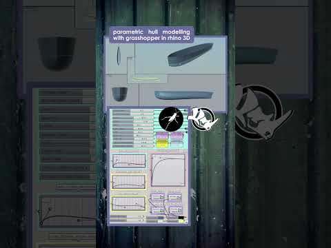
Unlocking Parametric Hull Generation in Rhino 3D with Grasshopper

Designing complex boat or ship hulls traditionally required hours of manual curve tweaking and surface reconstruction. However, with the rise of computational design, tools like Grasshopper have transformed how marine architects and 3D designers approach complex geometry. By pairing visual programming with Rhino 3D, you can easily automate and refine parametric hull generation in a fraction of the time.

Understanding Parametric Hull Generation

Parametric hull generation involves using mathematical algorithms and flexible parameters—such as beam width, draft, overall length, and bow entry angle—to define a vessel's hull geometry. Instead of manually dragging individual control points, designers can simply adjust sliders in Grasshopper to instantly update the entire 3D model. This approach allows for rapid prototyping, real-time design variations, and faster hydrodynamics testing.

Why Grasshopper and Rhino 3D Are the Ultimate Pair

As an industry-standard CAD platform, Rhino 3D provides exceptional freeform surface modeling capabilities. When seamlessly integrated with Grasshopper—its built-in visual programming editor—designers gain complete algorithmic control over their surface geometry.

By using Grasshopper for parametric hull modeling, you can: - Iterate Rapidly: Explore dozens of hull variations instantly without recreating geometry from scratch. - Maintain Precision: Ensure exact mathematical control over cross-sectional curves, waterlines, and lofted surfaces. - Optimize Performance: Connect geometry directly to analysis plugins for hydrostatic and structural feedback.

Essential Workflow for Building a Parametric Hull

  1. Define Key Parameters: Establish numerical input sliders for dimensions like length overall (LOA), beam, and draft.
  2. Generate Base Curves: Create dynamic cross-section curves and stem profiles driven directly by your parameter inputs.
  3. Form the Surface skin: Apply lofting or surface-from-network components to generate a smooth, fair hull skin.
  4. Analyze and Refine: Finetune your sliders to optimize the hull's fairing lines and hydrodynamics properties.

Conclusion

Mastering computational design opens up incredible technical freedom. Whether you are creating sleek luxury yacht concepts or commercial vessel designs, leveraging Grasshopper within Rhino 3D will drastically streamline your workflow and elevate your digital modeling capabilities.

Continue Reading | ความคิดเห็น

From Concept to Reality: Transforming 2D Designs into 3D Structures with Civil 3D

Tuesday, November 3, 2026

Have you ever wondered how a flat, two-dimensional blueprint transforms into a towering, modern structure? The journey from a simple CAD design to actual building construction is a masterclass in modern engineering, innovation, and digital precision. Today, advanced modeling technology makes it possible to visualize every beam, foundation, and terrain feature long before ground is ever broken.

The Blueprint Phase: Moving Beyond 2D Vectors

For decades, civil engineers relied strictly on 2D AutoCAD drawings to convey building plans. While effective, flat schematics often leave room for interpretation and spatial miscalculations on the construction site. By transitioning 2D concepts into detailed 3D digital environments, engineering teams can catch design flaws early, streamline cross-team collaboration, and present crystal-clear structural animations to stakeholders.

Unlocking Site Precision with Civil 3D

To turn complex architectural blueprints into real-world reality, modern civil engineers rely on powerful civil design and documentation tools. Utilizing Civil 3D allows engineers to map out site geometry, analyze surface terrain, and design essential supporting infrastructure with incredible accuracy. This intelligent, dynamic environment ensures that if a design modification occurs, associated elements automatically update, keeping the physical project vision aligned with the underlying data.

Furthermore, integrating Civil 3D workflows into the pre-construction phase bridges the gap between site development and building design. Engineers can simulate surface grading, model utility systems, and calculate earthwork volumes seamlessly, establishing a rock-solid foundation for the upcoming building.

From Digital Twin to Physical Reality

Once the 3D structural model and site animations are finalized, actual physical construction begins. Armed with precise spatial data, construction crews can execute site preparation, foundation pouring, and structural framing with far fewer errors and minimal project delays. What started as basic lines on a computer screen successfully evolves into a safe, functional, and aesthetically pleasing structure.

Understanding this transformation highlights the remarkable evolution of modern engineering—proving that digital precision is the true blueprint for our physical world.

Continue Reading | ความคิดเห็น

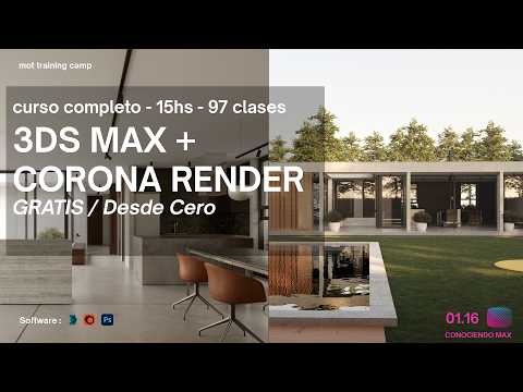
Master Spline Modeling in 3ds Max: A Complete ArchViz Guide

Are you ready to elevate your architectural visualization skills from scratch? Achieving photorealistic archviz projects requires a solid foundation in 3D modeling tools. Whether you are a complete beginner or an aspiring 3D artist looking to refine your workflow, 3ds Max remains the industry standard software for creating detailed, production-ready architectural models.

The Power of Splines and Lines in ArchViz

Before diving into complex lighting and texturing, every great 3D model starts with clean, precise geometry. In architectural modeling, lines and splines serve as the foundational blueprint. From drawing initial floor plans to defining custom wall profiles, crown moldings, and furniture frames, line work forms the backbone of accurate 3D structures. Mastering these vector-based controls allows you to build complex architectural shapes quickly while maintaining absolute precision.

Key Techniques for Working with Lines in 3ds Max

When creating complex architectural elements in 3ds Max, mastering splines and line tools is essential for an efficient workflow. Here are a few vital techniques every 3D artist should practice:

  • Extruding and Sweeping: Instantly transform 2D line profiles into 3D walls, cornices, or railings using powerful modifiers like Extrude, Sweep, and Bevel Profile.
  • Vertex Editing: Fine-tune corners and curves using Corner, Smooth, Bezier, and Bezier Corner vertex types for ultimate control over transitions.
  • Attaching and Boolean Operations: Combine multiple shapes or trim intersecting paths effortlessly to build intricate interior and exterior layouts without cluttering your scene hierarchy.

Bringing Geometry to Life with Corona Renderer

Once your base linework is properly structured, transitioning from 2D splines to 3D architectural volumes becomes seamless. Combining these precise linework techniques with Corona Renderer elevates your 3ds Max workflow even further. Corona's intuitive rendering engine allows you to apply realistic physical materials, set up natural sun and sky lighting, and generate photorealistic archviz renders effortlessly.

Start Building Your ArchViz Future Today

Learning 3D modeling doesn't have to be overwhelming. By breaking down complex projects into structured, step-by-step methods—starting with basic lines and splines—you can construct realistic architectural scenes with complete confidence. Practice these core linework fundamentals today and take your visualization projects to the next level!

Continue Reading | ความคิดเห็น

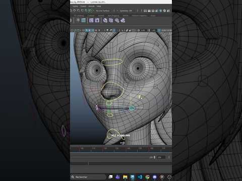
The Magic of Facial Rigging: How to Bring Characters to Life in Maya 3D

Monday, November 2, 2026

In the world of 3D animation, creating a compelling character model is only half the journey. The true magic happens when that character begins to express emotion, speak, and truly connect with the audience. Facial rigging is the vital bridge between a static 3D mesh and a living, breathing digital persona. By setting up complex expressions and intuitive controls, artists using Maya 3D can give digital characters a soul and bring their stories to life.

Why Facial Rigging Matters in Animation

Facial rigging involves constructing a digital skeleton and control system beneath a character's facial mesh. While body rigging focuses on large movements like walking or running, facial rigging deals with micro-expressions—the subtle arch of an eyebrow, the slight smirk of a lip, or the gentle squint of the eyes.

Without a well-designed rig, even the most detailed 3D sculpt remains stiff and emotionless. A high-quality facial rig allows animators to convey delicate storytelling nuances, transforming a generic digital asset into an unforgettable character that resonates deeply with viewers.

Crafting Expressive Rigging Systems in Maya 3D

When it comes to professional character setup, Maya 3D remains the industry-standard software for artists and animation studios worldwide. Its robust toolset enables riggers to combine blend shapes (shape keys) with joint-based rigging techniques seamlessly.

Blend shapes work exceptionally well for sculpting specific organic facial targets, such as smiles, frowns, or phonemes for lip-syncing. Meanwhile, joint-based controls provide dynamic flexibility for structural movements, such as jaw opening, tongue articulation, and cheek deformation. Utilizing the powerful node hierarchy and custom control curves within Maya 3D, riggers can build clean, user-friendly control panels that make the animation workflow smooth and expressive.

Elevate Your 3D Character Work

Mastering the art of facial rigging requires patience, continuous practice, and a keen eye for human anatomy and movement. Observing real-life facial mechanics and translating those subtle details into digital controls is what separates beginner work from professional quality.

Whether you are a hobbyist or an aspiring professional, taking the time to master character rigging will dramatically elevate the production value of your projects. Keep pushing your creative boundaries, study facial anatomy, and continue exploring the endless possibilities of 3D animation!

Continue Reading | ความคิดเห็น

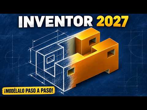
Mastering Inventor 3D: How to Model Parts and Prepare Them for 3D Printing

Additive manufacturing has revolutionized how we bring physical products to life, but every great print starts with a precise computer-aided design (CAD) model. If you are new to design software, learning Inventor 3D modeling is one of the most effective ways to master mechanical design and rapid prototyping. In this guide, we will explore the step-by-step process of creating a part from scratch in Autodesk Inventor 2027 and preparing it for seamless 3D printing.

Step 1: Interpreting Geometry and 2D Sketching

Before creating any solid geometry, you need to analyze the part's basic shape, symmetry, and key dimensions. Start by opening a new part file in Autodesk Inventor 2027 and selecting an appropriate work plane (such as the XY or XZ plane). Translate your blueprint or physical measurements into a clean 2D sketch using fundamental drawing tools like lines, circles, and arcs. Always apply geometric constraints and precise dimensional values to ensure your sketch is fully constrained, which prevents unwanted deformation as your model grows more complex.

Step 2: Transforming 2D Sketches into Solid Parts

Once your 2D sketch is fully defined, it is time to convert it into a solid object. The Extrude and Revolve tools allow you to add mass quickly, while cut operations enable you to create precise holes, slots, and complex internal cutouts. By taking advantage of Inventor 3D design features, you can easily apply fillets and chamfers to smooth sharp edges, reduce stress concentrations, or improve the visual appeal of your component. Building your parametric features logically ensures that any future modification takes only seconds to update.

Step 3: Exporting Your Model for 3D Printing

With your geometry complete, the final step is exporting the file for additive manufacturing. Navigate to the file export menu and select a universally recognized 3D printing format, such as STL or 3MF. Before saving, check your export resolution settings: choosing high refinement yields smoother curves on your physical print, whereas low refinement can result in visible faceting. Once exported, load the file into your preferred slicer software to generate the G-code for your 3D printer.

Final Thoughts

Developing proficiency in Inventor 3D design bridges the gap between digital concepts and real-world physical objects. By following a structured workflow—from sketch interpretation to final mesh export—you can reliably produce functional, high-quality models ready for 3D printing.

Continue Reading | ความคิดเห็น

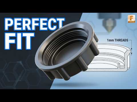
How to Design a Custom Canister Cap Using Fusion 360 3D

Have you ever lost the lid to a useful container or needed a custom-fit cap for a workshop storage jar? Instead of searching online for a replacement that might not fit correctly, you can easily design and print your own. By harnessing the power of Fusion 360 3D modeling, creating functional, real-world hardware becomes a simple and rewarding process.

In this guide, we will walk through the core steps of designing a 3D printable canister cap from scratch using basic parametric modeling techniques.

Step 1: Precise Measurements and Basic Sketching

Every successful 3D printing project begins with accurate measurements. Grab a digital caliper and measure the outer diameter of your canister’s neck, along with the depth of the rim.

Once you have your dimensions: 1. Open a new component and create a 2D sketch on the top plane. 2. Draw a center-diameter circle matching your canister's outer dimensions. Add a small tolerance (around 0.2mm to 0.4mm) to ensure the cap slides on smoothly without being too loose. 3. Extrude the circle upward to create the main body of the cap, then use the Shell tool to hollow out the inside.

Step 2: Adding Grips and Threads in Fusion 360 3D

One of the major benefits of working with Fusion 360 3D design tools is how effortlessly you can add functional and aesthetic details. A smooth plastic cap can be hard to twist, so adding knurling or ridges around the outside wall is essential.

To create an easy-to-grip texture: * Sketch a small triangular notch on the outer rim of the cap. * Use the Extrude tool to cut the notch down the length of the outer wall. * Apply a Circular Pattern to repeat this notch around the entire circumference.

If your canister uses screw threads, apply the built-in Thread tool to the inner cylinder wall. Make sure to check the "Modeled" box so the threads are sliced into the actual geometry for 3D printing.

Step 3: Exporting and Slicing Your Model

Once your cap design is complete, export the file as an STL or 3MF. Load the file into your preferred slicer program. For functional utility parts like canister caps, print with at least 3 wall perimeters and a 15–20% infill to ensure durability.

Start Creating Your Own Parts

Designing custom replacement components is one of the most practical uses for a desktop printer. Master the basics of Fusion 360 3D today, and start turning your practical everyday ideas into tangible prints!

Continue Reading | ความคิดเห็น

Master Revit 3D Modeling: A Beginner's Guide to Extrusion and Blend Forms

Sunday, November 1, 2026

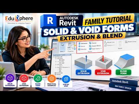
Creating detailed components in Autodesk Revit starts with mastering the Family Editor. Whether you are designing custom furniture, complex structural elements, or unique architectural features, understanding how to construct geometric forms is essential. In this guide, we’ll explore how to build custom components using Solid and Void Extrusions and Blends to elevate your Revit 3D modeling workflow.

Understanding Solid & Void Extrusions

Extrusion is the most fundamental creation tool in the Revit Family Editor. It works by taking a two-dimensional profile and pushing (extruding) it along a specified path to generate a volume.

  • Solid Extrusions: Ideal for creating basic 3D shapes such as columns, cabinetry, or flat surfaces. You simply draw a closed 2D sketch, set the start and end depths, and finish the form.
  • Void Extrusions: These operate in reverse. Instead of building mass, a void form cuts away geometry from existing solid shapes. Voids are essential for creating openings, recessed channels, or decorative cuts within your models.

Mastering the Blend Tool for Complex Geometry

When uniform extrusions are insufficient for your design, the Blend tool allows you to create smooth transitions between two entirely different shapes.

  • Top and Bottom Profiles: A blend requires defining two separate sketches: a base profile and a top profile. Revit automatically calculates and constructs the 3D geometry connecting them.
  • Practical Applications: Blends are perfect for creating tapered columns, smooth transitions in mechanical ductwork, or organic furniture pieces.
  • Combining with Voids: Just like extrusions, you can apply Void Blends to sculpt intricate, tapered cutouts inside your Revit 3D models.

Best Practices for Parametric Modeling

To make your families truly flexible, align and lock your solid and void sketches to reference planes. Assigning parametric dimensions to these reference planes ensures that your shapes resize dynamically without breaking the geometry.

Mastering these core tools allows you to handle virtually any design challenge in Revit 3D. Start combining extrusions and blends with void forms today to create clean, accurate, and professional BIM families for your architectural projects.

Continue Reading | ความคิดเห็น

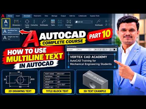
Master Multiline Text: A Step-by-Step Guide for AutoCAD 3D Users

Clear communication is essential when creating precise engineering drawings and architectural plans. Whether you are drafting basic 2D floor plans or working on complex AutoCAD 3D models, adding detailed annotations, dimensions, and explanatory notes ensures your designs are correctly understood. One of the most powerful annotation tools available in AutoCAD is the Multiline Text (MTEXT) feature.

In this quick guide, you will learn how to efficiently use Multiline Text to streamline your documentation workflow.

Why Choose Multiline Text Over Single Line Text?

Unlike Single Line Text, Multiline Text (MTEXT) gives you complete control over paragraph formatting, word wrapping, alignment, and styling. Key advantages include:

  • Advanced Formatting: Adjust font styles, text height, colors, and line spacing within a single text block.
  • Bullets and Lists: Easily create numbered or bulleted specifications directly on your technical drawings.
  • Columns and Margins: Organize extensive notes into clean, readable multi-column layouts without manual line breaks.

Step-by-Step: How to Use Multiline Text in AutoCAD

Using the MTEXT command is straightforward and fits seamlessly into any workflow, whether you are focusing on traditional drafting or detailed AutoCAD 3D projects.

  1. Activate the Command: Type MTEXT or the shortcut MT into the command line and press Enter. Alternatively, select Multiline Text from the Annotation panel on the Home ribbon tab.
  2. Specify the Boundary: Click once in your workspace to set the first corner of your text frame, then drag and click again to set the opposite corner. This bounding box defines the width of your text paragraph.
  3. Enter Your Content: The Text Editor contextual tab will automatically open. Type your technical notes, descriptions, or instructions inside the frame.
  4. Format the Appearance: Highlight any portion of your text to change its font style, height, justification, or insert special symbols (such as degree, diameter, or plus/minus symbols).
  5. Close and Save: Click Close Text Editor on the ribbon or click anywhere outside the text boundary box to apply the changes.

Tips for Better Annotation Management

To maintain consistency across large AutoCAD 3D assemblies or standard floor plans, always utilize defined Text Styles (STYLE command). Additionally, placing your MTEXT on dedicated annotation layers allows you to manage object visibility and plotting properties effortlessly.

Conclusion

Mastering Multiline Text is a fundamental skill for any CAD designer looking to produce clean, professional-grade documentation. Start incorporating MTEXT into your daily routine to save time and elevate the quality of your AutoCAD projects today!

Continue Reading | ความคิดเห็น

Unlocking the Secrets of Crowd Simulation with Autodesk 3D

Have you ever sat in a movie theater watching a historical war epic or a packed stadium scene filled with thousands of roaring fans and wondered, “How did they manage to hire so many extras?” The short answer is: they didn't!

Welcome to the fascinating world of crowd simulation, where visual effects (VFX) artists use powerful software solutions like Autodesk 3D suites to populate massive cinematic worlds with realistic digital human beings.

What is Crowd Simulation in VFX?

In modern filmmaking, coordinating thousands of real human extras is expensive, time-consuming, and logistically challenging. Crowd simulation is a specialized branch of visual effects where computer software generates hundreds, thousands, or even millions of autonomous digital characters—known as "agents"—within a single scene.

Rather than animating each character individually, artists give these digital extras unique behaviors, dynamic movements, and realistic physics so they act naturally within their environment.

How Do Artists Create Massive Digital Crowds?

Creating a believable digital crowd involves a seamless blend of technology and artistry:

  1. Character Modeling: Artists design several base 3D character models with variations in clothing, height, and textures to avoid noticeable duplication.
  2. Motion Capture (MoCap): Stunt actors and performers record foundational actions—such as walking, running, cheering, or fighting—which are converted into digital animation data.
  3. Behavioral AI and Rules: Integrated within industry-standard animation workflows powered by Autodesk 3D software, artists set AI rules for digital agents. This ensures characters navigate terrain, avoid walking through each other, and react dynamically to obstacles.
  4. Rendering & Compositing: Final lighting, shadow integration, and realistic depth of field are applied so the digital crowd merges seamlessly with live-action footage.

Why Crowd Simulation is Essential for Modern Movies

Beyond saving film studios millions of dollars in production costs, digital crowd simulation gives directors complete creative freedom. Weather conditions, camera angles, and dramatic collisions can be tweaked effortlessly without coordinating thousands of real people on set.

Whether it’s an immense fantasy army clashing on a battlefield or a futuristic city bustling with civilians, crowd simulation driven by flexible Autodesk 3D tools continues to push the boundaries of modern visual storytelling. The next time you see a massive crowd on the big screen, remember—you're looking at pure digital magic!

Continue Reading | ความคิดเห็น

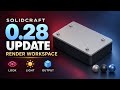
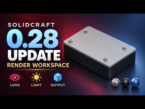
SolidCraft 0.28 Update: A Deep Dive into the New Render Workspace

Saturday, October 31, 2026

The latest SolidCraft 0.28 update is officially here, bringing a wave of powerful features designed to elevate your 3D design workflow. Among the most anticipated highlights of this release is the overhauled Render workspace, a dedicated environment built to turn your raw 3D models into stunning, photorealistic visuals.

Whether you are an engineer finalizing a complex CAD design or a creator bringing custom hardware to life, this update offers the tools you need to showcase your work in the best possible light.

Unlocking the Power of the Render Workspace

In version 0.28, the Render workspace takes center stage. The update introduces refined controls for lighting, material application, and camera management, allowing users to achieve high-end visualization directly within the application without relying on external rendering software.

Using a custom electronics enclosure project as a practical demonstration, the new tools showcase how seamlessly you can apply realistic textures—from matte plastics to brushed metallic finishes—and observe how light interacts with every edge and bezel. The streamlined UI ensures that both beginners and seasoned pros can configure environment settings quickly, significantly reducing setup time.

Real-Time Preview and Enhanced Material Options

One of the standout improvements in this release is the enhanced real-time preview capability. As you adjust material properties or tweak background environments, the feedback is instant and clear. This makes iterative aesthetic choices much smoother, as you no longer have to wait through long rendering test runs just to check a minor surface reflection or color adjustment.

Furthermore, the updated material library provides pre-configured shaders tailored for product design. Showing off enclosure snaps, internal mounting points, and polished exterior finishes has never looked this crisp. This level of visual fidelity makes SolidCraft an even more versatile solution for professional presentations and client pitches.

Upgrade and Elevate Your Designs

The 0.28 update represents a massive step forward in bridging the gap between technical design and high-impact visual representation. By mastering the Render workspace, you can transform your functional models into market-ready product renders with minimal effort.

If you haven’t updated your setup yet, now is the perfect time to open your software and explore all the powerful rendering capabilities waiting for you in SolidCraft 0.28!

Continue Reading | ความคิดเห็น

Streamline Your Engineering CAD Workflows: Eliminate Revision Drift and Project Delays

In today’s fast-paced technical landscape, managing complex engineering projects requires precision, speed, and seamless team collaboration. However, many organizations still struggle with the friction caused by inefficient document control systems. From lost drawings to chaotic file versions, mismanaged engineering CAD data frequently leads to project bottlenecks, costly rework, and missed deadlines.

The Hidden Cost of Fragmented Reviews and Revision Drift

One of the biggest hurdles technical teams face is revision drift. When multiple engineers, project managers, and external contractors collaborate across disparate channels, keeping track of the latest design iteration becomes a major operational headache. Fragmented team reviews conducted via scattered email threads and disjointed markup tools only aggravate the issue.

Without a centralized control hub, critical updates get overlooked, and team members end up working on outdated files. To keep projects moving forward smoothly, modern firms need a robust platform tailored specifically for engineering CAD management and document control.

Smarter Engineering Document Control with WiseINDEX

WiseINDEX directly addresses these pain points by providing a streamlined, intelligent approach to document control. Instead of losing valuable time searching for correct files or untangling conflicting feedback, WiseINDEX centralizes your project assets into an intuitive, secure ecosystem.

Key benefits of optimizing your workflow with WiseINDEX include:

  • A Single Source of Truth: Eliminate version confusion by ensuring every stakeholder accesses the correct, up-to-date drawings and specifications at all times.
  • Unified Team Collaboration: Consolidate reviews into a shared, transparent environment, replacing fragmented email chains with actionable design feedback.
  • Controlled Revision History: Automatically track every modification to prevent costly errors during fabrication or construction.

Accelerate Your Project Timelines

Managing your engineering CAD environment shouldn't slow your team down. By adopting specialized document management tools like WiseINDEX, you can eliminate structural inefficiencies, minimize project risks, and significantly boost your team’s productivity.

Ready to see how it works? Watch our complete walkthrough to discover how WiseINDEX transforms complex document management into an effortless, reliable workflow.

Continue Reading | ความคิดเห็น

How to Read an Engineering Drawing: A Complete Beginner's Guide

Stepping onto a construction site or opening a blueprint file for the first time can feel overwhelming. For students, fresh graduates, and site workers, mastering the skill of reading an engineering drawing from scratch is essential for career success. These technical drawings serve as the universal language of construction and design, translating complex architectural concepts into clear instructions for real-world execution.

Key Components Every Beginner Should Know

Before diving into complex site plans, it is important to understand the fundamental elements that make up a standard structural layout:

  • Title Block: Located at the bottom right corner, this section contains critical project metadata, including project name, drawing scale, author, date, and revision history.
  • Legend and Symbols: Drawings use standardized graphical symbols to represent materials, electrical points, plumbing lines, and structural members. Always refer to the legend to avoid misinterpretation.
  • Grid Lines and Dimensions: Numerical and alphabetical grid lines provide precise reference points across the site, allowing engineers to locate columns, walls, and foundations accurately.

A Step-by-Step Guide to Reading Blueprints

Interpreting a civil engineering drawing effectively requires a structured, step-by-step approach rather than trying to process the entire layout at once:

  1. Review the Title Block and General Notes: Always read the general notes first. They outline structural codes, material specifications, soil bearing capacities, and critical site instructions.
  2. Examine the Floor Plan View: The top-down plan view gives an overall understanding of spatial arrangements, room dimensions, wall thicknesses, and structural grid alignments.
  3. Analyze Elevations and Cross-Sections: While plan views show horizontal layouts, elevation drawings reveal vertical dimensions, floor heights, and structural levels. Cross-sections provide a deep look inside walls and foundations.
  4. Cross-Reference Detail Callouts: Small detail drawings explain complex structural connections, steel rebar arrangements, and material joining techniques.

Conclusion

Reading technical drawings with accuracy is a core competency that develops with practice. By breaking down drawings into digestible sections—starting with title blocks and moving through plans, elevations, and details—you can confidently navigate any construction blueprint on site.

Continue Reading | ความคิดเห็น

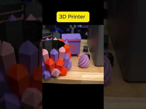
Transforming Digital 3D Graphics into Reality: Flashforge Creator 5 Review

A New Era of Multi-Tool 3D Printing

Bringing complex digital 3D graphics off the computer screen and into the physical world has always presented unique challenges, especially when dealing with multi-color and multi-material designs. Traditional single-extruder 3D printers often waste an immense amount of time and expensive filament "flushing" colors between layer transitions. The new Flashforge Creator 5 solves this frustration head-on with an innovative multi-toolhead system designed to maximize efficiency, speed, and print quality.

Four Tools, Minimal Filament Waste

The standout feature of the Flashforge Creator 5 is its four distinct toolheads. Instead of relying on a single nozzle to alternate between multiple filaments—which leads to long purge times and excessive wasted plastic—the Creator 5 switches seamlessly between separate tools.

This multi-tool architecture is a true game-changer for makers, designers, and engineers who work with intricate 3D graphics. Whether you are printing vibrant multi-colored prototypes, complex functional components, or multi-material models requiring dedicated soluble supports, the Flashforge Creator 5 reduces material flushing to an absolute minimum. The result is faster overall print times, sharper color separation, and significantly reduced operating costs.

Elevate Your Digital Workflow

Beyond its superior color-handling capabilities, the Flashforge Creator 5 offers a robust build volume, excellent structural stability, and seamless software integration. It bridges the gap between digital design and physical manufacturing, allowing creators to materialize detailed 3D graphics with unprecedented ease, accuracy, and reliability.

If you are looking to upgrade your additive manufacturing setup, now is a great time to buy. You can use the exclusive discount code C5CREATOR30 on the official website to get an extra $30 off the current promotional price.

Continue Reading | ความคิดเห็น

Popular Posts Today

 
Support : 3Dcadbrowser | Grabcad | 3Dcontentcentral | D | E | F | G
Copyright © 2028. Engineering 3DCad Appication - All Rights Reserved