Cad 3D Category

Showing posts with label Fusion 360. Show all posts

How to Design a Custom Canister Cap Using Fusion 360 3D

Monday, November 2, 2026
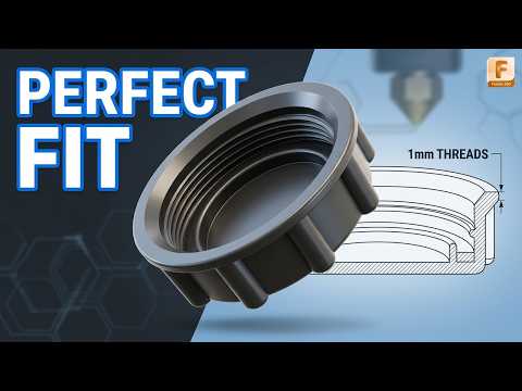
Have you ever lost the lid to a useful container or needed a custom-fit cap for a workshop storage jar? Instead of searching online for a replacement that might not fit correctly, you can easily design and print your own. By harnessing the power of Fusion 360 3D modeling, creating functional, real-world hardware becomes a simple and rewarding process.

In this guide, we will walk through the core steps of designing a 3D printable canister cap from scratch using basic parametric modeling techniques.

Step 1: Precise Measurements and Basic Sketching

Every successful 3D printing project begins with accurate measurements. Grab a digital caliper and measure the outer diameter of your canister’s neck, along with the depth of the rim.

Once you have your dimensions: 1. Open a new component and create a 2D sketch on the top plane. 2. Draw a center-diameter circle matching your canister's outer dimensions. Add a small tolerance (around 0.2mm to 0.4mm) to ensure the cap slides on smoothly without being too loose. 3. Extrude the circle upward to create the main body of the cap, then use the Shell tool to hollow out the inside.

Step 2: Adding Grips and Threads in Fusion 360 3D

One of the major benefits of working with Fusion 360 3D design tools is how effortlessly you can add functional and aesthetic details. A smooth plastic cap can be hard to twist, so adding knurling or ridges around the outside wall is essential.

To create an easy-to-grip texture: * Sketch a small triangular notch on the outer rim of the cap. * Use the Extrude tool to cut the notch down the length of the outer wall. * Apply a Circular Pattern to repeat this notch around the entire circumference.

If your canister uses screw threads, apply the built-in Thread tool to the inner cylinder wall. Make sure to check the "Modeled" box so the threads are sliced into the actual geometry for 3D printing.

Step 3: Exporting and Slicing Your Model

Once your cap design is complete, export the file as an STL or 3MF. Load the file into your preferred slicer program. For functional utility parts like canister caps, print with at least 3 wall perimeters and a 15–20% infill to ensure durability.

Start Creating Your Own Parts

Designing custom replacement components is one of the most practical uses for a desktop printer. Master the basics of Fusion 360 3D today, and start turning your practical everyday ideas into tangible prints!

Continue Reading | ความคิดเห็น

Master Sketch Constraints in Fusion 360 3D: A Beginner's Guide

Sunday, October 11, 2026

If you are new to the world of Fusion 360 3D design, sketch constraints can often feel like a stumbling block. You draw a shape, try to move a line, and suddenly your entire geometry collapses or moves unpredictably.

Understanding how sketch constraints work is the single most important step toward creating stable, parametric CAD models. In this guide, we will break down what constraints are, why you need them, and how to master the essential rules every beginner must know.

What Are Sketch Constraints?

In parametric CAD modeling, constraints are rules applied to 2D sketch elements—such as lines, arcs, and points—to control their position, size, and relationship to one another.

Instead of manually dimensioning every single edge, constraints allow you to define geometric intent. For instance, if two lines should always remain perpendicular, applying a constraint ensures they stay at a 90-degree angle no matter how much you tweak the rest of your design.

Why Are Constraints Essential in CAD?

Using constraints correctly transforms chaotic geometry into fully defined sketches. Here is why they matter:

  • Predictable Edits: When you change one dimension later in your project, a properly constrained sketch adjusts without breaking.
  • Error Prevention: Constraints prevent accidental shifts or warping when building complex assemblies.
  • Streamlined Workflow: Combining constraints with smart dimensions speeds up your modeling process, making your work in Fusion 360 3D far more efficient.

Key Constraints Every Beginner Should Know

While there are many constraints available, focusing on these core types will solve 90% of your beginner sketching frustrations:

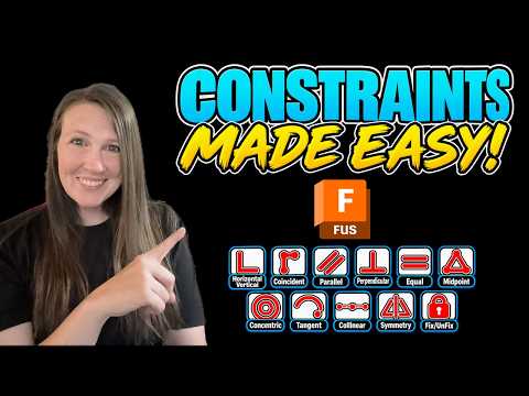
  1. Horizontal/Vertical: Forces lines to align horizontally or vertically relative to the sketch plane.
  2. Coincident: Connects two points together or snaps a point onto a line or curve.
  3. Tangent: Creates a smooth transition where a line meets a curve or circle without sharp angles.
  4. Equal: Forces two or more lines or circles to maintain the exact same length or radius.
  5. Parallel & Perpendicular: Keeps lines aligned in parallel or locked at right angles.
  6. Concentric: Aligns the center points of multiple circles or arcs.

Best Practices for a Clean Workflow

To keep your sketches tidy and manageable, follow these quick tips:

  • Look at Line Colors: In Fusion, blue lines mean geometry is unconstrained (it can still move), while black lines indicate fully constrained geometry. Aim for black lines before extruding!
  • Let Auto-Constraints Help: As you draw, subtle constraint icons will pop up automatically. Pay attention to them so you don't accidentally lock a line where you didn't mean to.
  • Combine Constraints and Dimensions: Use geometric constraints first to establish relationships, then add dimensions to set specific measurements.

By mastering these fundamental rules, you will eliminate modeling frustration and unleash the full parametric potential of Fusion 360 3D. Start practicing on simple 2D shapes today, and watch your CAD confidence soar!

Continue Reading | ความคิดเห็น

Fusion 360 Body vs. Component: The Ultimate 3D CAD Guide

Tuesday, September 1, 2026

When diving into modern 3D CAD software like Autodesk Fusion 360, one of the first major hurdles beginners encounter is understanding the difference between a Body and a Component. While both represent 3D geometry on your screen, treating them as interchangeable is a common mistake that can derail your design workflow later on.

Let's break down these core concepts with practical examples so you can structure your models with confidence.

What is a Body?

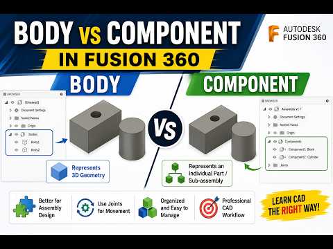
In Fusion 360, a Body is a single, continuous 3D solid or surface object. Think of a body as a lump of clay or a solid block of material. You can extrude, cut, combine, and fillet bodies to build complex physical geometry.

However, bodies have strict structural limitations: - They cannot have motion joints applied directly to them. - They do not possess their own independent coordinate system (origin). - They are best suited for initial modeling steps, single-part designs, or temporary geometric tools.

What is a Component?

A Component is a self-contained organizational unit that holds geometry (bodies), sketches, construction planes, and its own unique origin. If a body is a single piece of material, a component is a complete functional part or sub-assembly.

Key features of components include: - Joints and Motion: Components can be moved relative to each other using joints to simulate real-world mechanical motion. - Assembly Structure: Components appear as distinct items in Bills of Materials (BOM) and technical drawings. - Reusability: You can create multiple instances of a component; editing one automatically updates all other instances.

Key Differences at a Glance

To streamline your 3D CAD workflow, keep these distinctions in mind: 1. Motion & Mechanics: Need your parts to articulate or move? You must use components to apply joints. 2. Drawings & Metadata: Creating detailed assembly documentation? Only components carry distinct part numbers and metadata. 3. Hierarchy: Bodies reside inside components. A component can contain multiple bodies, but a body cannot contain a component.

Best Practice: The Golden Rule

A great rule of thumb in Fusion 360 is to create a new component before you start sketching whenever you are designing a multi-part assembly. This habit keeps your browser tree organized, avoids timeline errors, and builds a professional 3D CAD design structure from the very beginning.

By mastering when to use bodies versus components, you'll create cleaner, more flexible, and fully functional 3D models every time!

3D CAD
Continue Reading | ความคิดเห็น

Is Code-Based 3D CAD Better Than Fusion 360? An OpenSCAD Review

Tuesday, August 18, 2026

Have you ever wondered what it would be like to design 3D prints using lines of code instead of dragging a mouse across a screen? While traditional visual design software dominates the maker space, script-based modeling is offering an exciting alternative for how enthusiasts and engineers approach 3D CAD projects.

In this quick review, we take a look at OpenSCAD—the popular open-source, script-based tool—and explore whether writing code can truly replace GUI-heavy software like Fusion 360.

What Makes Code-Based Modeling Different?

Unlike traditional 3D CAD programs that rely on graphical user interfaces (GUIs), OpenSCAD operates much like a programmer's text editor. Instead of selecting tools to sketch, push, and pull shapes on a digital canvas, you write precise scripts using dimensions, variables, and mathematical functions to compile your 3D models.

This code-driven approach offers several distinct advantages: - Absolute Precision: Define exact numerical dimensions for perfect tolerances and mechanical fit. - Parametric Power: Easily modify a single variable (such as wall thickness or bolt hole size) to update the entire model automatically. - Easy Version Control: Since your 3D design is stored as a lightweight text file, tracking revisions using system tools like Git becomes effortless.

Fusion 360 vs. OpenSCAD: Visual vs. Programmatic

When comparing Fusion 360 to a code-based alternative like OpenSCAD, the right choice usually comes down to how you prefer to visualize and solve spatial problems.

Fusion 360 excels at organic sculpting, complex freeform surfaces, and rapid visual iteration. It is intuitive for designers and artists who prefer a direct, interactive feedback loop while manipulating objects in a 3D workspace.

On the other hand, OpenSCAD shines when creating functional, geometric, and parametric parts. If you have a background in software development, engineering, or mathematics, building objects through code often feels faster, cleaner, and far more reliable.

Which Tool Should You Choose?

So, is script-based design actually better? There is no one-size-fits-all answer. If your focus is on artistic sculpts or fluid ergonomics, visual tools like Fusion 360 remain superior. However, if you prioritize programmatic flexibility, customizability, and algorithmic precision, adopting a script-based 3D CAD workflow with OpenSCAD might completely transform your 3D printing process.

3D CAD
Continue Reading | ความคิดเห็น

The Future of Design: Is Code-Based 3D CAD Better Than Fusion 360?

Monday, August 17, 2026

In the rapidly evolving world of 3D printing, the tools we use to bring our ideas to life are just as important as the printers themselves. Most hobbyists and professionals are well-acquainted with the visual, mouse-driven interface of industry giants like Fusion 360. However, a different philosophy is gaining traction: designing through code. This brings us to a fascinating comparison between traditional modeling and script-based 3D CAD tools like OpenSCAD.

The Shift from Mouse to Code

Fusion 360 represents the gold standard for many, offering a robust, "What You See Is What You Get" (WYSIWYG) environment. You click, you drag, and you sculpt. It is intuitive for those with a background in visual arts or traditional engineering. But what if you could define your objects using logic and variables instead? OpenSCAD is a "programmer’s solid 3D modeler." Instead of drawing, you write scripts that define geometric shapes and the mathematical operations that combine them.

Why Precision Matters in 3D CAD

One of the primary advantages of using a code-based 3D CAD system is the level of precision and "true" parametric control it offers. In a script-based environment, every dimension is a variable. If you are designing a complex mechanical part and realize a hole diameter needs to change, you don't have to click through layers of a design history. You simply update a single line of code, and the entire model recalculates perfectly. This makes it an incredibly powerful tool for functional parts where mathematical accuracy is non-negotiable.

Open-Source Freedom vs. Professional Suites

OpenSCAD is open-source and remarkably lightweight, meaning it can run on almost any hardware without a subscription fee. This stands in stark contrast to professional suites that often require high-end workstations and cloud connectivity. For makers who already have a background in programming, the transition to script-based design can feel more natural than navigating the dense, multi-level menus of a traditional mouse-based interface.

Choosing the Right Tool for the Job

Is code-based design actually "better"? The answer depends on your project. If you are modeling organic shapes, character figurines, or complex aesthetic curves, Fusion 360 is likely the superior choice. However, for those focused on mechanical engineering, custom brackets, or repetitive geometric patterns, the logic-driven workflow of script-based 3D CAD is hard to beat. By understanding the strengths of both, you can choose the best workflow to turn your digital concepts into physical reality.

3D CAD
Continue Reading | ความคิดเห็น

Download Full Heat Exchange System 3D CAD Model

Friday, November 14, 2025

Explore and download a complete 3D CAD model of a Heat Exchange System directly from GrabCAD. This high-quality engineering model is perfect for students, engineers, and designers who want to study or simulate heat transfer systems in detail.

The model includes all major components of a heat exchange system such as pipes, valves, tanks, and heat exchangers. It is compatible with major CAD software including SolidWorks, AutoCAD, and Fusion 360.

Key Features:

  • Fully detailed 3D CAD assembly
  • High-accuracy components for engineering simulation
  • Ready for analysis and design modification
  • Compatible with multiple CAD platforms

Download the CAD files now and enhance your mechanical design projects or engineering simulations.

Click here to download the Heat Exchange System CAD files

Keywords: 3D CAD model, heat exchange system, CAD files download, SolidWorks model, AutoCAD assembly, engineering simulation, mechanical design, 3D engineering model

Labels: 3D CAD, Heat Exchange, CAD Download, Mechanical Design, Engineering Model, SolidWorks, AutoCAD, Fusion 360


Continue Reading | ความคิดเห็น

How to Download High-Quality 3D Models from GrabCAD in Minutes

Tuesday, November 11, 2025

If you are a designer, engineer, or 3D artist, finding high-quality 3D models can save you a lot of time during your design process. One of the best platforms for this purpose is GrabCAD. It offers a massive library of free CAD files shared by engineers and creators worldwide. In this guide, we will show you how to download 3D models from GrabCAD quickly and safely.

Step 1: Visit the GrabCAD Library

Go to GrabCAD Library. You can search for models such as SolidWorks parts, Fusion 360 assemblies, or even 3D printable files. The search bar lets you filter results by software type, file format, or popularity.

Step 2: Choose a Verified or Popular Model

Look for 3D models that have many downloads, likes, or comments. This ensures that you are getting a high-quality CAD model. Always check the file details such as format (STEP, STL, SLDPRT, etc.) and model resolution before downloading.

Step 3: Click the Download Button

Once you’ve found the right model, click the Download Files button. You may need to sign in to your GrabCAD account to complete the download. The files are usually compressed in a ZIP folder containing multiple CAD formats.

Step 4: Import and Modify in Your CAD Software

After downloading, extract the ZIP file and open it with your favorite CAD program such as SolidWorks, AutoCAD, or Fusion 360. You can then edit, scale, or render the model based on your project needs.

Why Choose GrabCAD for 3D Models?

  • Huge community of professional engineers
  • Free access to thousands of realistic 3D CAD models
  • Supports multiple formats: STL, STEP, IGES, SLDPRT, DWG
  • Perfect for mechanical design, robotics, or 3D printing projects

Final Thoughts

GrabCAD is an excellent platform for anyone looking to download professional 3D models quickly and efficiently. With a few clicks, you can find ready-to-use CAD files for any project — whether you’re working on industrial design, prototyping, or product visualization.

Start exploring today and enhance your creative workflow with free 3D model downloads from GrabCAD!


Keywords:

GrabCAD 3D models, download free CAD files, high-quality 3D models, SolidWorks parts, Fusion 360 3D design, 3D printable models, engineering CAD library, free 3D download, mechanical design models

Continue Reading | ความคิดเห็น

Discover the Best Free 3D CAD Models on GrabCAD

If you are an engineer, designer, or hobbyist who loves creating 3D models, GrabCAD is one of the best platforms to find high-quality and free downloadable CAD files. In this post, we have carefully selected the Top 10 Free 3D CAD Models on GrabCAD that you must see and download today. These models cover a wide range of categories, including mechanical parts, robots, vehicles, and industrial tools.

1. SCARA Robot 5 DOF

A detailed 3D model of a SCARA Robot with five degrees of freedom, perfect for automation and motion control projects. This model is highly customizable and can be used for simulation or educational purposes.

2. Two-Jaw Gripper with NEMA 17 Motor

This gripper model includes realistic components and precise dimensions, making it a great reference for robotic arm designs.

3. Gearbox Assembly

A beautifully designed gearbox assembly model showing internal gear movement and accurate mechanical detail.

4. Pneumatic Cylinder

This CAD file offers a 3D pneumatic cylinder model ideal for mechanical projects and fluid control system simulations.

5. Industrial Fan Blade

An optimized industrial fan blade design that demonstrates aerodynamic efficiency and realistic modeling.

6. Car Engine 3D Model

A complete car engine model featuring pistons, crankshaft, and valves. Excellent for automotive design enthusiasts.

7. 3D Printed Drone Frame

A lightweight and 3D printable drone frame designed for small UAV projects or prototyping.

8. CNC Machine Base

This CNC base model gives you a realistic starting point for your custom milling machine design.

9. Mechanical Coupling

A precision-designed shaft coupling model that can be used for machine part alignment and simulation.

10. Automotive Suspension System

A detailed suspension system model for automotive applications, showing spring, damper, and linkage components.

Why Download CAD Models from GrabCAD?

GrabCAD offers a vast community of engineers who share free 3D CAD files for learning, design inspiration, and collaboration. Downloading models from GrabCAD saves time, improves productivity, and helps you understand real-world mechanical designs.

Conclusion

These Top 10 Free 3D CAD Models on GrabCAD are just a glimpse of what’s available on the platform. Whether you’re using SolidWorks, AutoCAD, Fusion 360, or CATIA, these files can enhance your next design project. Visit GrabCAD Library and start downloading today!

Continue Reading | ความคิดเห็น

Popular Posts Today

 
Support : 3Dcadbrowser | Grabcad | 3Dcontentcentral | D | E | F | G
Copyright © 2028. Engineering 3DCad Appication - All Rights Reserved