Cad 3D Category

Showing posts with label 3D Printing. Show all posts

From Design to Print: How to Resolve Accuracy Issues Between 3D CAD and Slicers

Friday, September 11, 2026

In the world of professional engineering and product design, precision is everything. You spend hours perfecting a model, ensuring every dimension is exact down to the micron. However, many creators face a frustrating hurdle: the discrepancy between the original digital model and the final sliced file. Bridging this gap is essential for anyone looking to transition from hobbyist printing to professional-grade manufacturing.

Understanding the Discrepancy

The journey from a 3D CAD environment to a physical object involves several translations. When you export your design—typically as an STL or STEP file—and import it into a slicer, the software must interpret geometric data into G-code. During this process, "rounding errors" or mesh approximations can occur. If your export settings are too low, a perfectly smooth curve in your design software might become a series of jagged facets in the slicer, leading to dimensional inaccuracies that can ruin a professional assembly.

Calibration is Key

To ensure your physical output matches your 3D CAD intent, you must account for material shrinkage and machine tolerances. Professional projects often require "designing for the process." This means testing how your specific printer and filament react. If a bolt needs to fit into a hole, you may need to apply a small offset in your modeling stage to compensate for the way the plastic expands or contracts during the cooling phase.

Optimizing Your Workflow for Professional Results

For those handling complex projects, such as integrated PCB housings or mechanical enclosures, using high-quality fabrication services can eliminate much of the guesswork. Services like PCBWay offer professional 3D printing and PCB assembly that utilize industrial-grade equipment capable of much tighter tolerances than standard desktop units.

When preparing your files, always export at the highest sensible resolution and double-check your unit scales (mm vs. inches) before hitting the "Slice" button. By syncing your 3D CAD settings with your slicer’s specific capabilities, you can ensure that the "real-world" product is a perfect reflection of your digital vision.

Conclusion

Solving the delta between a model and a print is what separates a prototype from a finished product. By understanding how slicers interpret geometry and adjusting your design workflow accordingly, you can achieve professional-level accuracy every time. Whether you are printing in-house or outsourcing to a factory, precision starts with a well-optimized file.

Continue Reading | ความคิดเห็น

Mastering 3D CAD to Slicer Precision for Professional 3D Printing

Thursday, September 10, 2026

Transitioning a digital design into a physical object is the core of modern engineering and rapid prototyping. However, professionals frequently encounter a frustrating issue during this process: dimensional discrepancies between the original 3D CAD model and the sliced file prepared for 3D printing. Understanding and resolving these errors is critical for delivering high-precision components in professional projects.

Why Discrepancies Occur Between CAD and Slicer

When you export a parametric 3D CAD design into a mesh format like STL or OBJ, the software converts smooth curves into a network of flat triangles. This tessellation process inevitably introduces geometric approximations.

When this mesh file is imported into a slicer, additional variables come into play. Slicer settings—such as layer height, extrusion width, wall ordering, and material shrinkage—can further distort the original dimensions. In professional applications where tight tolerances are non-negotiable, even a 0.1mm deviation can prevent PCB assemblies or enclosure snaps from fitting together properly.

How to Eliminate Dimensional Errors

To bridge the gap between your digital design and the final 3D print, follow these key strategies:

  • Optimize Export Resolution: When saving your model in your design software, fine-tune the chord deviation and angle tolerance settings. High-density mesh exports reduce polygon approximation errors.
  • Calibrate Horizontal Expansion: Most modern slicers offer "Horizontal Expansion" or "Slicing Tolerance" features. Adjusting these settings helps compensate for wall swelling caused by plastic flow.
  • Account for Material Shrinkage: Filament types like ABS or PETG shrink as they cool. Scale your model slightly in the slicer to offset predicted material contraction.

Relying on Professional Fabrication Services

For complex, mission-critical projects where desktop printers fall short, turning to commercial manufacturing platforms can save both time and resources. Professional fabrication services, such as PCBWay, provide industrial-grade 3D printing and PCB prototyping solutions. By using high-end additive manufacturing equipment, these platforms ensure that your complex 3D CAD assemblies are manufactured with incredible accuracy, eliminating the trial-and-error phase of slicer calibration.

Conclusion

Achieving perfect alignment between your CAD design and slicer software is essential for professional manufacturing success. By refining your export settings, calibrating slicer offsets, and leveraging professional fabrication partners, you can ensure that your final printed parts match your engineering specifications every single time.

Continue Reading | ความคิดเห็น

Mastering 3D CAD: How to Eliminate Tolerances Between Your Design and the Final Print

Wednesday, September 9, 2026

In the world of professional engineering and product design, precision is not just a goal—it is a requirement. However, many designers face a common frustration: a model that looks perfect in its 3D CAD environment often encounters significant dimensional errors once it passes through a slicer and reaches the 3D printer. Bridging this gap between the digital "ideal" and the physical "reality" is the key to professional-grade manufacturing.

The Digital Discrepancy: Why CAD and Slicers Conflict

The journey from a 3D CAD file to a physical object involves several layers of translation. While your design software works with precise mathematical curves and coordinates, a slicer must convert that data into a mesh (usually STL) and then into G-code toolpaths. During this conversion, small rounding errors, mesh density issues, and material shrinkage factors can lead to "tolerances" that ruin a press-fit part or a mechanical assembly.

To solve these discrepancies, professionals must look beyond the default settings. Understanding how your slicer interprets the wall thickness and hole diameters defined in your original design is the first step toward calibration.

Optimizing Your Workflow for Professional Projects

To ensure your project maintains its integrity, you must account for "Horizontal Expansion" and "Hole Expansion" within your slicing software. These settings allow you to compensate for the natural outward flow of plastic. However, the most effective way to minimize error is to design with the manufacturing process in mind. By applying a global tolerance standard (such as 0.1mm to 0.2mm) directly within your 3D CAD workspace, you create a buffer that accommodates the physical limitations of FDM or resin printing.

Scaling Up with Professional Services

Sometimes, high-stakes professional projects require more precision than a desktop setup can provide. This is where professional fabrication services like PCBWay become invaluable. Whether you are integrating a custom PCB into a 3D-printed enclosure or requiring industrial-grade SLS printing, outsourcing to a specialized facility ensures that the tight tolerances you’ve calculated in your design are mirrored in the final product.

Conclusion

Solving the variance between design and production is what separates hobbyist prints from professional prototypes. By mastering your 3D CAD tools and understanding the logic of your slicing software, you can significantly reduce waste and ensure that every part fits perfectly the first time. Precision begins at the design stage—make sure your workflow is ready for the challenge.

Continue Reading | ความคิดเห็น

Unleashing Innovation: Inside the Modern 3D CAD Lab

Tuesday, September 8, 2026

In today’s fast-paced technological landscape, engineering education and industrial design are undergoing a massive transformation. At the heart of this revolution is the state-of-the-art 3D CAD lab, a dedicated workspace where students, researchers, and engineers turn complex virtual ideas into tangible reality. Computer-Aided Design has evolved far beyond basic 2D drafting, becoming the cornerstone of modern manufacturing, robotics, and structural engineering.

Transforming Virtual Designs into Physical Prototypes

A modern design facility serves as a vital bridge between theoretical engineering concepts and practical applications. Inside a fully equipped 3D CAD lab, creators learn to manipulate complex three-dimensional geometries, run real-time stress simulations, and optimize mechanical components long before any physical materials are used.

When paired with additive manufacturing technologies like 3D printing, the capabilities of modern design tools expand exponentially. Engineers can conceptualize a part in the digital workspace, refine its dimensions, and send it directly to a 3D printer. This seamless integration allows for rapid prototyping—reducing development cycles from months to just hours and encouraging a mindset of experimentation and continuous improvement.

Key Advantages of Hands-On Design Facilities

Industry standards now require modern engineering graduates to possess strong practical expertise in digital design software. Working directly within a dedicated lab environment provides several distinct benefits:

  • Enhanced Spatial Visualization: Designers can view, rotate, and analyze complex assemblies from every angle.
  • Early Defect Detection: Virtual stress testing helps identify structural weaknesses and interference issues prior to production.
  • Resource Conservation: Testing performance digitally drastically reduces material waste and prototyping costs.

Shaping the Future of Digital Manufacturing

As modern manufacturing shifts toward automation and digital twin integration, mastery of digital modeling tools is essential. Modern 3D CAD software empowers multidisciplinary teams—from mechanical to electrical engineers—to collaborate on a single unified platform.

By investing time in advanced design labs, aspiring engineers gain the hands-on expertise required to solve real-world industrial challenges. These facilities do not just teach software; they cultivate the problem-solving mindset necessary to design the technological advancements of tomorrow.

Continue Reading | ความคิดเห็น

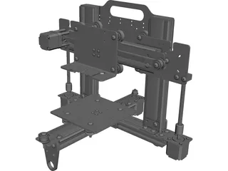
Download Universal 3D Printer CAD Model (SolidWorks, CATIA, AutoCAD)

Saturday, September 5, 2026

Preview Image

Upgrade your engineering workflow with this detailed 3D Printer CAD model. Designed for seamless integration into technical presentations, workspace layout planning, and digital twin simulations, this model provides an accurate visual representation of standard additive manufacturing hardware.

Key Features & Highlights

  • Multi-Software Support: Ready for import into major CAD platforms without file corruption.
  • Assembly Layout Ready: Perfect for space planning in factory floor models and workshop environments.
  • Clean Geometry: Optimized structure suitable for rendering, visualization, and digital prototyping.

Supported CAD Software Formats

Compatible with AutoCAD, SolidWorks, Autodesk Inventor, Pro/ENGINEER (ProE), Siemens NX, PTC Creo, CATIA, ACIS (.sat), and standard universal exchange formats (STEP/IGES).


Continue Reading | ความคิดเห็น

Plasticity Review: Is This the Best 3D CAD Tool for Artists and 3D Printing?

Thursday, September 3, 2026

For years, 3D printing enthusiasts and digital artists faced a difficult choice when picking modeling software: endure the steep, technical learning curve of traditional engineering programs, or use artistic sculptors like Blender that often struggle with exact dimensions and solid geometry. Enter Plasticity—a hotkey-driven, direct-modeling tool designed specifically to bridge this gap. But can it truly streamline your workflow for physical creations?

Rethinking Direct Modeling for Designers

Unlike traditional parametric software that relies heavily on complex feature trees and rigid constraints, Plasticity focuses on a fast, direct-modeling workflow. It borrows the intuitive hotkey navigation popular in digital art tools, making it feel second nature to artists and sculptors.

By prioritizing direct face pushing, pulling, and curve manipulation, it removes the friction between creative ideation and technical execution. This unique design philosophy makes 3D CAD accessible to creative minds who previously shied away from engineering-heavy interfaces.

Precision Meets Artistic Freedom

One of the biggest hurdles when preparing models for 3D printing is ensuring clean, solid geometry. Traditional mesh modeling software can easily produce non-manifold edges and clipping faces that result in failed slices. Plasticity solves this by operating as a true NURBS modeling engine under the hood.

This means you get the aesthetic freedom of polygonal modeling combined with the dimensional accuracy of modern 3D CAD software. Creating smooth fillets, sharp chamfers, and precise boolean cuts is remarkably fluid, yielding high-quality STL and STEP files that are instantly ready for your 3D printer.

The Verdict: Should You Make the Switch?

If your design process relies heavily on parametric history trees—where changing an early sketch dimension needs to automatically update a complex mechanical assembly—traditional software may still be necessary. However, if you are an artist, concept designer, or hobbyist who wants to turn creative ideas into physical prints quickly, Plasticity is a game-changer.

It strikes a rare balance between speed, usability, and technical precision, proving that 3D CAD doesn't have to feel like drafting software—it can feel as natural and expressive as digital sketching.

3D CAD
Continue Reading | ความคิดเห็น

CadQuery vs OpenSCAD: Which Code-Based 3D CAD Tool Is Best?

Monday, August 24, 2026

Code-driven modeling has revolutionized how makers, engineers, and digital artists approach mechanical design and additive manufacturing. Unlike traditional drag-and-drop geometric editors, programmatic modeling tools allow users to build precise, parameter-driven models using code. When evaluating open-source, code-based 3D CAD solutions, two prominent software options lead the space: OpenSCAD and CadQuery.

Here is a breakdown of how these two powerful tools compare to help you decide which one fits your workflow best.

OpenSCAD: The Lightweight Classic

OpenSCAD has long been the standard for code-driven parametric design. It operates using its own dedicated domain-specific scripting language, making it relatively straightforward for beginners to learn basic geometric operations.

Key Advantages: - Ease of Entry: A simple syntax that makes creating basic parametric shapes fast and straightforward. - Vast Community: A massive user base with thousands of existing open-source scripts, libraries, and online tutorials. - Fast Setup: Lightweight, standalone application that runs smoothly on almost any system.

Drawbacks: - Language Limitations: Lacks standard programming constructs like object-oriented design or rich third-party library integration. - Geometry Engine: Relies primarily on Constructive Solid Geometry (CSG), which can make complex filleting and chamfering challenging.

CadQuery: The Python-Powered Evolution

CadQuery is a modern, Python-based framework designed to elevate programmatic modeling. Powered by the industrial-grade Open CASCADE geometry kernel, it utilizes Boundary Representation (B-Rep) to generate highly complex mechanical shapes.

Key Advantages: - Full Python Integration: Leverage the vast Python ecosystem, including math libraries, external data sources, and advanced scripting capabilities. - Robust Kernel: Superior handling of organic curves, complex fillets, shells, and direct STEP/IGES file exports. - Human-Readable Syntax: Uses a fluent script interface designed to produce clean, maintainable code.

Drawbacks: - Steeper Learning Curve: Requires a working knowledge of Python and environment setup. - Smaller Ecosystem: While growing rapidly, it has fewer ready-to-use community scripts than OpenSCAD.

Final Verdict: Choosing the Right 3D CAD Software

Selecting the best programmatic 3D CAD platform depends on your background and project scope. If you need a quick, easy-to-learn tool for basic 3D printing models, OpenSCAD is a reliable and time-tested option. However, if you already know Python and require professional-grade engineering features like step file outputs and precise fillets, CadQuery represents the next generation of code-driven 3D CAD design.

3D CAD
Continue Reading | ความคิดเห็น

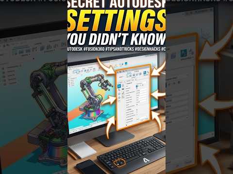
The Game-Changing Autodesk Secret Tip Every 3D CAD Designer Needs to Know

Saturday, August 22, 2026

Whether you are a seasoned engineer or a hobbyist creating your first prototype, working with powerful software like Autodesk can sometimes feel overwhelming. However, mastering hidden feature shortcuts can transform your digital workspace overnight. If you want to elevate your design process, understanding the best 3D CAD techniques is essential for saving time, boosting precision, and reducing costly errors.

Why Small Tweaks Make a Big Difference

Autodesk software is packed with robust tools, yet many creators rely only on standard default settings. By uncovering lesser-known options—such as customized hotkeys, advanced parameters management, or dynamic workspace settings—you can dramatically streamline your design phase. Instead of manually repeating complex modeling steps, leveraging these built-in secrets allows you to focus on innovation rather than tedious menu navigation.

The Hidden Autodesk Tip You Need to Try

One of the most effective tricks in Autodesk involves optimizing your mesh export settings and parametric constraints before sending files to a 3D printer. Many designers face issues with broken geometry or incorrect tolerances after exporting their files.

By fine-tuning your default export density and taking advantage of direct editing capabilities, you can refine your geometry instantly without disrupting your design history. This simple adjustment ensures that your 3D CAD models transition smoothly from the digital screen to the physical print bed without losing critical dimensional accuracy.

Perfecting Your Prints with Smart Design Habits

Creating a flawless physical object requires more than just drawing basic shapes; it demands a strategy tailored specifically for additive manufacturing. When working with modern 3D CAD software, keeping wall thicknesses consistent, applying strategic fillets to stress-bearing edges, and checking for non-manifold geometry beforehand will save you hours of print failures and wasted material.

Final Thoughts

Unlocking simple yet powerful tips within Autodesk isn't just about working faster—it is about achieving higher-quality results with far fewer headaches. Try integrating these hidden workflow hacks into your next modeling session, and watch your project efficiency skyrocket.

3D CAD
Continue Reading | ความคิดเห็น

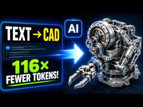
Text to 3D CAD: How AI-Powered Multi-Agent Systems Are Changing Manufacturing

Thursday, August 20, 2026

Imagine describing a physical object in plain English and watching a complete, 3D printable file materialize in seconds. What once sounded like science fiction is now becoming a reality through cutting-edge artificial intelligence. Enter MAC (Multi-Agent CAD), an innovative system designed to bridge the gap between simple text prompts and functional manufacturing models.

What is Multi-Agent CAD (MAC)?

Traditional 3D CAD software often requires years of practice, precise mathematical inputs, and complex manual drafting. MAC changes this paradigm by using a collaborative network of specialized AI agents. Instead of relying on a single AI model to guess the exact geometry of an object, MAC splits the workload among multiple intelligent agents. Some agents analyze the text prompt, others generate the underlying parametric code, and additional agents inspect the design to ensure structural viability.

This multi-agent approach allows the system to generate clean, editable, and highly accurate parametric models rather than distorted 3D meshes. By translating descriptive text directly into code-based geometry, MAC creates physical parts that are optimized for production and ready for 3D printing.

Why Text-to-CAD Technology Matters

The integration of generative AI into 3D CAD workflows brings several major advantages to engineers, industrial designers, and hobbyists alike:

  • Rapid Prototyping: Turn creative concepts into physical objects without spending hours on initial sketching and baseline modeling.
  • Accessibility: Lower the barrier to entry, allowing non-experts to generate custom parts without navigating steep software learning curves.
  • Parametric Accuracy: Because MAC produces code-driven geometry rather than mere visual surfaces, the output remains fully customizable, precise, and structurally sound.

The Future of Digital Design

While human expertise remains essential for complex mechanical engineering, tools like MAC represent a massive leap forward for rapid design iteration. The future of 3D CAD is evolving into a hybrid process—one where humans provide creative intent and AI handles the tedious drafting tasks. Whether you are an experienced engineer or a desktop manufacturing enthusiast, text-driven CAD modeling is set to redefine how we bring digital ideas into the real world.

3D CAD
Continue Reading | ความคิดเห็น

From Concept to Reality: How 3D CAD and 3D Printing Transform Product Development

Wednesday, August 19, 2026

In the fast-paced world of modern manufacturing, the journey from a spark of inspiration to a physical product has been radically shortened. This revolution is driven by two powerhouse technologies: advanced 3D printing and sophisticated 3D CAD software. Together, they allow designers and engineers to iterate faster, reduce costs, and bring functional prototypes to life with unprecedented precision.

The Foundation: Design with Precision

Every great product begins as a digital blueprint. Using 3D CAD (Computer-Aided Design), developers can create intricate geometries and mechanical assemblies that were once impossible to visualize. This digital stage is crucial because it allows for virtual testing and stress analysis before a single cent is spent on materials. By perfecting the design in a digital environment, businesses ensure that the final physical prototype will function exactly as intended.

Choosing the Right Tool for the Job

Once the digital model is ready, the next step is selecting the appropriate 3D printing technology. Not all printers are created equal, and the choice often depends on the specific requirements of the product development stage:

  • FDM (Fused Deposition Modeling): Ideal for early-stage conceptual models and basic functional testing due to its cost-effectiveness and wide range of thermoplastic materials.
  • SLA (Stereolithography): Perfect for parts requiring high detail and a smooth surface finish, such as jewelry or intricate consumer electronics housings.
  • SLS (Selective Laser Sintering): The go-to for industrial-grade, durable prototypes and end-use parts that need to withstand significant mechanical stress.

Accelerating the Iteration Cycle

The true magic of integrating 3D CAD with 3D printing lies in the speed of the feedback loop. In traditional manufacturing, creating a mold or a tool could take weeks. Today, a designer can identify a flaw in a physical prototype, adjust the digital file, and start printing a revised version in a matter of hours. This "fail fast" approach allows teams to refine ergonomics, aesthetics, and mechanical fit in record time.

Conclusion

3D printing is no longer just a hobbyist’s tool; it is a cornerstone of professional product development. By mastering the synergy between digital design and physical production, innovators can navigate the complex path from a simple idea to a market-ready product with confidence and efficiency. Whether you are an entrepreneur or a seasoned engineer, leveraging these technologies is the key to staying competitive in today's industrial landscape.

3D CAD
Continue Reading | ความคิดเห็น

Is Code-Based 3D CAD Better Than Fusion 360? An OpenSCAD Review

Tuesday, August 18, 2026

Have you ever wondered what it would be like to design 3D prints using lines of code instead of dragging a mouse across a screen? While traditional visual design software dominates the maker space, script-based modeling is offering an exciting alternative for how enthusiasts and engineers approach 3D CAD projects.

In this quick review, we take a look at OpenSCAD—the popular open-source, script-based tool—and explore whether writing code can truly replace GUI-heavy software like Fusion 360.

What Makes Code-Based Modeling Different?

Unlike traditional 3D CAD programs that rely on graphical user interfaces (GUIs), OpenSCAD operates much like a programmer's text editor. Instead of selecting tools to sketch, push, and pull shapes on a digital canvas, you write precise scripts using dimensions, variables, and mathematical functions to compile your 3D models.

This code-driven approach offers several distinct advantages: - Absolute Precision: Define exact numerical dimensions for perfect tolerances and mechanical fit. - Parametric Power: Easily modify a single variable (such as wall thickness or bolt hole size) to update the entire model automatically. - Easy Version Control: Since your 3D design is stored as a lightweight text file, tracking revisions using system tools like Git becomes effortless.

Fusion 360 vs. OpenSCAD: Visual vs. Programmatic

When comparing Fusion 360 to a code-based alternative like OpenSCAD, the right choice usually comes down to how you prefer to visualize and solve spatial problems.

Fusion 360 excels at organic sculpting, complex freeform surfaces, and rapid visual iteration. It is intuitive for designers and artists who prefer a direct, interactive feedback loop while manipulating objects in a 3D workspace.

On the other hand, OpenSCAD shines when creating functional, geometric, and parametric parts. If you have a background in software development, engineering, or mathematics, building objects through code often feels faster, cleaner, and far more reliable.

Which Tool Should You Choose?

So, is script-based design actually better? There is no one-size-fits-all answer. If your focus is on artistic sculpts or fluid ergonomics, visual tools like Fusion 360 remain superior. However, if you prioritize programmatic flexibility, customizability, and algorithmic precision, adopting a script-based 3D CAD workflow with OpenSCAD might completely transform your 3D printing process.

3D CAD
Continue Reading | ความคิดเห็น

From 3D CAD to Reality: How 3D Printing Accelerates Product Development

Monday, August 17, 2026

In today’s fast-paced market, the ability to rapidly iterate on a design is what separates successful brands from the rest. The journey from a conceptual sketch to a tangible, functional product used to take months of back-and-forth with manufacturers. However, the integration of additive manufacturing has revolutionized this timeline, allowing designers to fail fast and innovate even faster.

The Foundation: Starting with 3D CAD

Before a single layer of material is printed, every great product begins in a digital environment. Using 3D CAD (Computer-Aided Design) software, engineers and designers can visualize complex geometries, test mechanical fitments, and ensure that every component works in harmony. This digital blueprint serves as the essential roadmap; without a precise model, the transition to a physical prototype would be impossible.

Choosing the Right 3D Printing Technology

Once your 3D CAD model is finalized, the next step is selecting the printing technology that best suits your goals. Not all 3D printers are created equal, and the choice depends on whether you need a visual model or a functional part:

  • FDM (Fused Deposition Modeling): The most common and cost-effective method, ideal for basic form testing and durable, low-cost structural parts.
  • SLA (Stereolithography): This technology uses a resin and a laser to create incredibly high-detail prototypes with smooth surface finishes, perfect for consumer electronics and jewelry.
  • SLS (Selective Laser Sintering): Utilizing a powder bed, SLS produces functional, end-use parts with high strength and heat resistance, often used for industrial applications.

Bridging the Gap to Production

3D printing bridges the gap between a digital file and a functional prototype. By utilizing 3D CAD data to create physical samples in-house, companies can identify design flaws early in the cycle, saving thousands of dollars in potential tooling costs. This iterative process allows for real-world testing, ergonomic evaluation, and stakeholder feedback long before the final production run.

Whether you are an individual inventor or part of a large engineering team, understanding the synergy between digital design and 3D printing is the key to turning your next big idea into a reality. By mastering these tools, you can ensure your product development process is as efficient and cost-effective as possible.

3D CAD
Continue Reading | ความคิดเห็น

The Future of Design: Is Code-Based 3D CAD Better Than Fusion 360?

In the rapidly evolving world of 3D printing, the tools we use to bring our ideas to life are just as important as the printers themselves. Most hobbyists and professionals are well-acquainted with the visual, mouse-driven interface of industry giants like Fusion 360. However, a different philosophy is gaining traction: designing through code. This brings us to a fascinating comparison between traditional modeling and script-based 3D CAD tools like OpenSCAD.

The Shift from Mouse to Code

Fusion 360 represents the gold standard for many, offering a robust, "What You See Is What You Get" (WYSIWYG) environment. You click, you drag, and you sculpt. It is intuitive for those with a background in visual arts or traditional engineering. But what if you could define your objects using logic and variables instead? OpenSCAD is a "programmer’s solid 3D modeler." Instead of drawing, you write scripts that define geometric shapes and the mathematical operations that combine them.

Why Precision Matters in 3D CAD

One of the primary advantages of using a code-based 3D CAD system is the level of precision and "true" parametric control it offers. In a script-based environment, every dimension is a variable. If you are designing a complex mechanical part and realize a hole diameter needs to change, you don't have to click through layers of a design history. You simply update a single line of code, and the entire model recalculates perfectly. This makes it an incredibly powerful tool for functional parts where mathematical accuracy is non-negotiable.

Open-Source Freedom vs. Professional Suites

OpenSCAD is open-source and remarkably lightweight, meaning it can run on almost any hardware without a subscription fee. This stands in stark contrast to professional suites that often require high-end workstations and cloud connectivity. For makers who already have a background in programming, the transition to script-based design can feel more natural than navigating the dense, multi-level menus of a traditional mouse-based interface.

Choosing the Right Tool for the Job

Is code-based design actually "better"? The answer depends on your project. If you are modeling organic shapes, character figurines, or complex aesthetic curves, Fusion 360 is likely the superior choice. However, for those focused on mechanical engineering, custom brackets, or repetitive geometric patterns, the logic-driven workflow of script-based 3D CAD is hard to beat. By understanding the strengths of both, you can choose the best workflow to turn your digital concepts into physical reality.

3D CAD
Continue Reading | ความคิดเห็น

From 3D CAD to Prototype: How 3D Printing Powers Product Development

Turning a brilliant concept into a tangible, market-ready product used to take months of painstaking labor and excessive tooling costs. Today, rapid prototyping has completely transformed the hardware landscape. By pairing digital design tools with modern additive manufacturing, engineers and designers can now bring physical prototypes to life in a matter of hours.

From Digital Design to Physical Prototype

Every successful product development journey starts in the digital realm. Designers use advanced 3D CAD software to draft, stress-test, and refine complex geometries before sending them to a physical machine. This digital foundation is critical because 3D printers rely on precise mathematical data to construct objects layer by layer.

By perfecting your model within a 3D CAD environment, you can catch critical design flaws early, optimize structural integrity, and dramatically reduce raw material waste long before entering mass production.

Exploring Key Types of 3D Printers

Once your concept is finalized in software, selecting the right 3D printing technology is essential for accurate functional testing. The three most widely used printer types in product development include:

  • Fused Deposition Modeling (FDM): Best suited for early-stage visual concepts and quick structural models using standard thermoplastics.
  • Stereolithography (SLA): Utilizes a laser to cure liquid resin into high-resolution components, ideal for parts requiring fine details and smooth surface finishes.
  • Selective Laser Sintering (SLS): Uses a high-power laser to fuse polymer powders, creating exceptionally strong, complex functional prototypes without needing support structures.

Accelerating Innovation and Time-to-Market

Seamlessly bridging your 3D CAD workflow with the appropriate modern 3D printing technology gives your team a decisive competitive edge. Physical iterations that previously required weeks of external machining can now be executed overnight in-house. Whether you are an independent creator or part of a enterprise R&D division, leveraging these tools will help you innovate faster, mitigate development risks, and bring better products to market.

3D CAD
Continue Reading | ความคิดเห็น

From 3D CAD to Physical Prototype: How 3D Printing Accelerates Product Development

Bringing a new product to market used to require months of expensive tooling, trial-and-error, and manual craftsmanship. Today, the fusion of digital design and additive manufacturing has completely transformed the product creation workflow. By pairing powerful 3D CAD software with modern 3D printing technologies, engineers and innovators can transform a simple idea into a fully functional prototype in a matter of hours.

From Digital Visions to 3D CAD Blueprints

Every physical product starts as a digital concept. Utilizing advanced 3D CAD tools, product designers can build precise digital models, simulate structural stresses, and refine ergonomics long before spending money on raw materials. These detailed parametric models serve as the master blueprint for the entire development cycle, ensuring every dimension, clearance, and aesthetic feature is perfected virtually before physical production begins.

Types of 3D Printers for Product Prototyping

Once your 3D CAD file is prepared and exported, selecting the right additive manufacturing technology is crucial for achieving your prototyping goals. The most common 3D printing methods include:

  • Fused Deposition Modeling (FDM): The most accessible option, ideal for quick visual models, early-stage geometric validation, and low-cost structural parts using thermoplastic filaments.
  • Stereolithography (SLA): Uses a UV laser to cure liquid resin into hardened plastic, producing exceptionally smooth surface finishes and ultra-fine details suitable for high-precision components.
  • Selective Laser Sintering (SLS): Uses a laser to fuse powdered material layer by layer, creating high-strength, durable functional parts without requiring dedicated support structures.

Accelerating the Product Iteration Cycle

The primary advantage of combining digital design with 3D printing is speed. Traditional manufacturing methods often force teams to wait weeks for sample parts. Additive manufacturing allows rapid, on-demand iteration. If testing reveals a design flaw, engineers can quickly modify the digital file and print a new iteration overnight.

Shrinking these feedback loops allows engineering teams to minimize development costs, eliminate design errors early, and drastically reduce time-to-market. Whether you are an independent creator or part of an enterprise engineering team, integrating modern 3D printing into your design pipeline is the key to faster, smarter innovation.

3D CAD
Continue Reading | ความคิดเห็น

Free Boeing 737 Airplane 3D Model for Printing - High Quality STL

Friday, February 6, 2026

Looking for a high-quality Boeing 737 3D model for your next printing project? This detailed airplane model is specifically designed for 3D printing enthusiasts and aviation fans.

Key Features of this Boeing 737 Model:

  • Format: Optimized STL file for 3D Printing.
  • Detail: Realistic aircraft proportions based on the Boeing 737 commercial jet.
  • Versatility: Perfect for desktop displays, educational projects, or collection dioramas.

Why Download This Model?

This free 3D aircraft model provides a great balance between detail and printability. Whether you are using an FDM or Resin printer, the geometry is structured to ensure a smooth printing process. It is a must-have for anyone building a 3D printed airport or airplane collection.

Ready to start printing?

Click the link below to visit the official download page on TurboSquid:

Download Free Boeing 737 3D Model

Note: Please check the licensing terms on the provider's website before use.

Continue Reading | ความคิดเห็น

Free 3D Model: Old Artisan Wave Pendant - Jewelry Design Resource

Thursday, January 22, 2026

Enhance Your Jewelry Projects with the Old Artisan Wave Pendant 3D Model

Looking for a unique, vintage-inspired piece for your digital jewelry collection? Download this Free Old Artisan Wave Pendant 3D model. This intricately designed accessory features a classic wave pattern, perfect for 3D artists, jewelers, and hobbyists looking for high-quality 3D printable jewelry or realistic rendering assets.

Key Highlights:

  • Style: Vintage Artisan / Nautical Wave
  • Usage: 3D Printing, Digital Sculpting, Jewelry Visualization
  • Compatibility: Optimized for major 3D software (Check source for formats)
  • SEO Optimized: Free 3D Jewelry Model, Artisan Pendant, Wave Jewelry Design

This Wave Pendant 3D model is inspired by traditional craftsmanship, blending organic curves with a timeless aesthetic. Whether you are practicing your rendering skills or looking for a base model for your next jewelry line, this free resource is a must-have.

Ready to add this to your library?

DOWNLOAD FREE 3D MODEL HERE

Note: Please check the license on the source website (TurboSquid) before use for commercial projects.

3D Model, Free Download, Jewelry Design, Artisan Pendant, Wave Pendant, 3D Printing, TurboSquid, Digital Art

Continue Reading | ความคิดเห็น

Download Free 3D Model: SCAR from TurboSquid

Monday, December 22, 2025

Discover a high-quality 3D model of the SCAR available for free download. This detailed and realistic SCAR 3D model is perfect for game development, animation, visualization, and 3D printing. The model includes all necessary textures and is ready to use in your projects.

Key Features:

  • High-quality textures and materials
  • Fully optimized for 3D rendering
  • Compatible with most 3D software
  • Realistic SCAR design

Get your free 3D SCAR model now from TurboSquid:

Download Free SCAR 3D Model

Boost your 3D projects with this ready-to-use SCAR model and save time on modeling!

3D model, SCAR, free download, TurboSquid, 3D assets, game assets, animation, visualization, 3D printing

Continue Reading | ความคิดเห็น

Free 3D Jewelry Snake Ring Model for 3D Printing

Thursday, December 18, 2025

Looking for a stunning 3D printable jewelry model? Download this free 3D snake ring suitable for all sizes. Perfect for 3D printing, jewelry design, and CAD projects. This high-quality 3D model comes ready to use and can be imported into your favorite 3D software.

Features:

  • Free to download and use
  • High-detail snake ring design
  • Compatible with most 3D printing software
  • Optimized for 3D modeling and jewelry design

Download the 3D model here: Free 3D Jewelry Snake Ring

This snake ring 3D model is ideal for 3D printing jewelry enthusiasts, CAD designers, and anyone looking for free 3D printable models. Enhance your jewelry 3D collection today with this high-quality 3D ring design.

3D printing,jewelry design,free 3D model,snake ring,3D printable model,CAD model,3D jewelry,3D modeling

Continue Reading | ความคิดเห็น

Free 3D David Star Gold Pendant Model Download

This article provides a free 3D model download of a David Star gold pendant, suitable for jewelry design, 3D printing, rendering, and product visualization projects.

The 3D pendant model features a classic Star of David design with a polished gold appearance. It is ideal for designers, jewelers, and creators who need a high-quality free jewelry 3D model for commercial or personal use.

3D Model Details

  • Model Type: Jewelry Pendant
  • Design: Star of David
  • Material Style: Gold
  • Category: Free 3D Jewelry Model

Free Download Link

You can download the free 3D model directly from the official source below:

👉 Download Free David Star Gold Pendant 3D Model

This free 3D model is perfect for use in rendering software, 3D printing workflows, and digital jewelry presentations.

free 3d model, jewelry 3d model, gold pendant, david star pendant, free 3d download, jewelry design, 3d printing


Continue Reading | ความคิดเห็น

Popular Posts Today

 
Support : 3Dcadbrowser | Grabcad | 3Dcontentcentral | D | E | F | G
Copyright © 2028. Engineering 3DCad Appication - All Rights Reserved