Cad 3D Category

Showing posts with label Autodesk Inventor. Show all posts

Step-by-Step Guide: How to Create a 3D Flange Hub with Inventor 3D

Thursday, October 22, 2026

Mechanical design requires precision, speed, and the right CAD tools to bring complex components to life. If you are looking to enhance your computer-aided design skills, learning how to model standard mechanical parts is the best way to start. In this guide, we will explore how to create a detailed Flange Hub using the powerful capabilities of Inventor 3D software.

What is a Flange Hub?

A flange hub is a vital mechanical component used to connect pipes, valves, pumps, and other equipment to form a seamless piping system. It provides strength, stability, and easy access for maintenance or modification. Because of its symmetric features and precise hole patterns, modeling a flange hub is an excellent exercise for beginners and intermediate designers aiming to master parametric modeling.

Key Steps to Model a Flange Hub

Creating a flange hub involves a logical workflow that utilizes essential modeling tools:

  1. Create the Base Sketch: Start by opening a new part file (.ipt) and selecting a 2D plane. Draw the cross-sectional profile of the hub, ensuring you apply accurate constraints and dimensions for the inner bore, outer hub diameter, and overall thickness.
  2. Apply the Revolve Feature: Instead of extruding multiple cylindrical layers, use the Revolve tool to turn your 2D profile into a solid body around a central axis. This is one of the most efficient techniques in Inventor 3D for creating symmetrical rotational parts.
  3. Drill the Mounting Holes: Create a sketch on the flat face of the flange ring. Place a circle for a bolt hole on the specified Pitch Circle Diameter (PCD) and use the Extrude Cut command to create the hole.
  4. Use the Circular Pattern Tool: Rather than drawing every bolt hole manually, duplicate the single hole around the central axis using the Circular Pattern tool for fast, precise spacing.
  5. Apply Fillets and Chamfers: Finish the model by adding chamfers to sharp edges to facilitate assembly and applying fillets to internal corners to eliminate stress concentration points.

Final Thoughts

Mastering these core CAD techniques will significantly improve your modeling speed and accuracy. Whether you are an engineering student, a CAD enthusiast, or a professional, practicing real-world components with Inventor 3D builds a strong design foundation. Watch the detailed video tutorial on the DodiCAD channel to follow along step-by-step and refine your modeling skills today!

Continue Reading | ความคิดเห็น

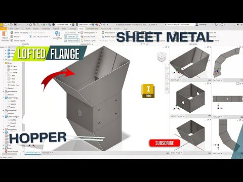
Master Sheet Metal Hopper Design in Inventor 3D: A Step-by-Step Guide

Monday, October 12, 2026

Designing custom sheet metal components can be a daunting task if you do not use the right CAD workflows. Whether you are creating material handling systems, ductwork, or industrial machinery, learning how to model a sheet metal hopper efficiently is an essential skill. By leveraging the powerful capabilities of Inventor 3D software, engineers and designers can seamlessly bridge the gap between initial 3D concept modeling and real-world fabrication.

Understanding the Power of the Lofted Flange

One of the most efficient tools for creating sheet metal hoppers and transition pieces is the Lofted Flange command. Unlike standard flanges that extend directly from straight edges, a lofted flange allows you to join two distinct closed or open profiles across separate work planes.

When designing complex sheet metal transitions in Inventor 3D, the Lofted Flange tool automatically calculates the necessary bends, material thickness, and relief cuts required for accurate manufacturing. This ensures that your model isn't just a visually appealing shape, but a functional, fabricable component ready for the shop floor.

Key Steps in the Hopper Fabrication Workflow

To build a professional-grade sheet metal hopper using real fabrication techniques, follow this streamlined CAD workflow:

  1. Set Up Offset Planes: Create parallel work planes representing the top opening and the bottom discharge outlet of your hopper.
  2. Draw Profile Sketches: Sketch the required geometry on each plane (such as a large rectangle on top and a smaller circle or square at the bottom). Apply sketch fillets to ensure smooth press brake or roll-forming bends.
  3. Apply Sheet Metal Rules: Define your material type, sheet thickness, and unfold rules beforehand to maintain accurate design intent.
  4. Generate the Lofted Flange: Select your two profiles using the Lofted Flange tool, specifying your preferred forming method (die-formed or press-brake bent).
  5. Create the Flat Pattern: Convert your 3D model into a 2D flat pattern with a single click to generate precise cutting templates for laser or plasma cutting machines.

Streamline Your Fabrication Process Today

Taking the time to master these practical workflow techniques in Inventor 3D will save you hours during production, eliminate material waste, and improve overall design accuracy. Start incorporating the Lofted Flange tool into your project routine today to take your sheet metal modeling skills to the next level!

Continue Reading | ความคิดเห็น

Mastering Autodesk 3D: How to Design a Main Shaft with Inner & Outer Splines

Saturday, October 10, 2026

Mechanical design often requires creating complex cylindrical components that transmit power efficiently. One of the most fundamental parts in power transmission systems is the main shaft, frequently customized with inner and outer splines to ensure seamless torque transfer. Whether you are a mechanical engineering student or a seasoned professional, mastering Autodesk 3D software is crucial for creating accurate and manufacturable shaft models.

Understanding Inner and Outer Splines

Splines are ridges or teeth on a drive shaft that mesh with matching grooves in a mating piece to transfer rotational motion and torque.

  • Outer Splines: Located on the external surface of the shaft, these teeth fit into the internal spline of a gear, hub, or coupling.
  • Inner Splines: Machined inside a hollow section or bore of the shaft, these allow secondary shafts or splined components to insert directly inside.

Designing both features on a single main shaft requires a structured workflow to maintain proper dimensions, strength, and tolerances.

Key Steps to Modeling a Splined Shaft

  1. Establish the Base Shaft Geometry: Start by creating the primary shaft body using basic revolve or extrude features. Ensure all primary reference planes are set correctly.
  2. Model the Outer Spline: Sketch the precise tooth profile on the outer diameter. Use circular pattern features to replicate the tooth profile uniformly around the central axis.
  3. Create the Inner Spline: Define a centered bore along the longitudinal axis. Sketch the internal spline profile and apply a cut-extrude command to form the inner teeth.
  4. Apply Stress Relief Features: Add fillets and chamfers at key transitions to minimize stress concentrations and prepare the design for manufacturing.

Creating splines efficiently requires a clean geometry setup in your Autodesk 3D workspace so that parameters can be easily updated later if design specifications change.

Essential Tips for Precise Mechanical Design

To ensure your 3D model is accurate and ready for simulation or production: * Use Parametric Constraints: Fully constrain your sketches using exact dimensions, pitch diameters, and tooth counts rather than visually estimating shapes. * Leverage Standard Libraries: Utilize built-in design accelerators whenever possible to generate standardized spline profiles according to ISO or ANSI standards.

With consistent practice, you can elevate your mechanical modeling expertise and streamline your engineering workflow using Autodesk 3D tools. Start building your main shaft model today to master these key techniques!

Continue Reading | ความคิดเห็น

Deutz F2L511 air cooled diesel engine | 3D Model CAD flie for download free.

Sunday, September 24, 2017


Details
Uploaded:September 4th, 2017
Softwares:Autodesk Inventor, Other, Rendering
Categories:Energy and Power
Tags:german, cooled, air, mechanical, diesel, engine


Downloads Cad flie : https://grabcad.com/library/deutz-f2l511-engine-1
Continue Reading | ความคิดเห็น

Butterfly valve DN100 Monoflange type. | 3D Model CAD flie for download free.

Saturday, September 23, 2017


Details
Uploaded:October 22nd, 2015
Softwares:AutoCAD, STEP / IGES, Rendering, Autodesk Inventor
Categories:Components, Industrial design, Piping
Tags:butterflyvalve, din, autodesk, valves, piping, inventor, butterfly, flow, autocad, valve, solidworks

Downloads Cad flie : https://grabcad.com/library/butterfly-valve-dn100-monoflange-type-1
Continue Reading | ความคิดเห็น

Multi-stage High Pressure pump coupled to Booster | 3D Model CAD flie for download free.

Sunday, September 10, 2017


Details
Uploaded:September 6th, 2015
Softwares:Autodesk Inventor, Rendering
Categories:Components, Industrial design, Machine design
Tags:booster, pump

Downloads Cad flie : https://grabcad.com/library/multi-stage-high-pressure-pump-coupled-to-booster-1
Continue Reading | ความคิดเห็น

Filter set Assey | 3D Model CAD flie for download free.


can be used on Reverse Osmosis Plants as secondary filters.

Details
Uploaded:September 6th, 2015
Softwares:Autodesk Inventor, STEP / IGES, Rendering
Categories:Components, Industrial design, Machine design
Tags:set, filter

Downloads Cad flie : https://grabcad.com/library/filter-set-assey-2
Continue Reading | ความคิดเห็น

Manifold with valves | 3D Model CAD flie for download free.


Details
Uploaded:October 10th, 2015
Softwares:Rendering, STEP / IGES
Categories:Components, Construction
Tags:manifold, water

Downloads Cad flie : https://grabcad.com/library/manifold-with-valves-1
Continue Reading | ความคิดเห็น

Water Distribution Manifold with Flange DN80-PE90-PN16 | 3D Model CAD flie for download free.


Details
Uploaded:October 12th, 2015
Softwares:Rendering, Autodesk Inventor
Categories:Components, Construction
Tags:distribution, water

Downloads Cad flie : https://grabcad.com/library/manifold-with-valves-1
Continue Reading | ความคิดเห็น

High Pressure Vessel Assey for Desalinaton Plant | 3D Model CAD flie for download free.


Details
Uploaded:October 12th, 2015
Softwares:Autodesk Inventor, Rendering
Categories:Components, Industrial design
Tags:desalination

Downloads Cad flie : https://grabcad.com/library/high-pressure-vessel-assey-for-desalinaton-plant-1
Continue Reading | ความคิดเห็น

The boundary wall is buried and with a curved roof. | 3D Model CAD flie for download free.


Details
Uploaded:October 13th, 2015
Softwares:Autodesk Inventor, Rendering
Categories:Architecture, Components, Construction
Tags:fuel, storage

Downloads Cad flie : https://grabcad.com/library/fuel-storage-with-boundary-1

Continue Reading | ความคิดเห็น

Curved Roof for general purpose.| 3D Model CAD flie for download free.


Details
Uploaded:October 13th, 2015
Softwares:Autodesk Inventor, Rendering
Categories:Architecture, Components, Construction
Tags:roof

Downloads Cad flie : https://grabcad.com/library/curved-roof-1
Continue Reading | ความคิดเห็น

Needle Valve 1000PSI, 1/2" | 3D Model CAD flie for download free.


Needle Valve 1000PSI, 1/2".
can be used on reverse osmosis systems.


Details
Uploaded:September 8th, 2017
Softwares:Autodesk Inventor, STEP / IGES, Rendering
Categories:Components
Tags:1000psi, 1-2, valve, needle

Downloads Cad flie : https://grabcad.com/library/needle-valve-1000psi-1-2-1
Continue Reading | ความคิดเห็น

hydraulic Directional Valve Solenoid Operated DHG-04 | 3D Model CAD flie for download free.


Details
Uploaded:September 10th, 2015
Softwares:Autodesk Inventor, Rendering
Categories:
Tags:directional, valve

Downloads Cad flie : https://grabcad.com/library/hydraulic-directional-valve-solenoid-operated-dhg-04-1
Continue Reading | ความคิดเห็น

DN40 BW NO - Metal 3-piece ball valve | 3D Model CAD flie for download free.

Saturday, September 9, 2017


Details
Uploaded:April 15th, 2016
Softwares:Other, Autodesk Inventor, Rendering
Categories:Components, Industrial design, Piping
Tags:dn40, content, library, center, fittings, autodesk, valves, ball, model, inventor, cad, 3d, valve

3D CAD model for Autodesk Inventor
■ Three piece ball valve with buttwelding ends
■ Diameter: DN40
■ Operation: manual
■ Position: open

Full range 3D CAD libraries for Autodesk Inventor can be found on our website:

http://www.wyalo.com
Continue Reading | ความคิดเห็น

Three piece ball valve DN50 PN16 | 3D Model CAD flie for download free.


Details
Uploaded:September 7th, 2015
Softwares:AutoCAD, STEP / IGES, Rendering
Categories:Components, Industrial design, Piping
Tags:ballvalves, ballvalve, din, free, autodesk, valves, ball, inventor, autocad, valve, solidworks

Three piece ball valve, DN50 PN16 flanges

The download includes an "open" and a "closed" version of the ball valve.

Free 3d model in step and Autocad dwg file format.

Wyalo on Google+:

https://plus.google.com/+Wyalo3Dcadmodels/posts

Wyalo website: www.wyalo.com
Continue Reading | ความคิดเห็น

Popular Posts Today

 
Support : 3Dcadbrowser | Grabcad | 3Dcontentcentral | D | E | F | G
Copyright © 2028. Engineering 3DCad Appication - All Rights Reserved