Cad 3D Category

Showing posts with label Product Design. Show all posts

Mastering Bottle Modeling: Final Steps to Perfect Your 3D CAD Design

Monday, September 7, 2026
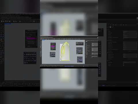
Creating sleek, functional industrial products requires precision, patience, and the right digital tools. Designing a custom bottle involves mastering curvature, surface continuity, and ergonomic details. In this final installment of our modeling series, we wrap up our bottle project and explore how modern 3D CAD tools allow designers to take concepts from a simple sketch to a manufacturing-ready 3D model.

Perfecting the Details in Industrial Design

The final stage of any product modeling workflow is where the true craftsmanship shows. Fine-tuning edge fillets, ensuring smooth surface transitions, and finalizing bottle threading are critical steps. Utilizing powerful 3D CAD software like Rhinoceros (Rhino) ensures that every curve is mathematically precise, eliminating potential manufacturing defects long before physical prototyping begins.

During this concluding phase, designers focus on several essential elements: - Surface Continuity: Achieving seamless blends between complex surfaces for a clean, premium visual aesthetic. - Precision Tolerances: Fine-tuning wall thickness and neck closures so structural components fit together effortlessly. - Product Visualization: Applying realistic materials and lighting to evaluate ergonomics and overall brand appeal.

Why Master 3D CAD for Packaging Design?

Packaging design is a dynamic industry where technical accuracy and high visual impact are equally important. By leveraging advanced 3D CAD techniques, industrial designers gain complete control over intricate geometries. This makes it far easier to iterate, refine, and present bottle containers, closures, and labeling surfaces with professional accuracy.

Watch the Full Video Tutorial

Ready to see the entire step-by-step workflow in action? While this quick preview highlights the final touches, you can master every technique from start to finish in our comprehensive video guide.

Don't miss a single step—watch the complete walkthrough here: Watch the Full Rhino 3D Bottle Tutorial. Take your modeling expertise to the next level and start crafting production-ready product designs today!

Continue Reading | ความคิดเห็น

Fusion 360 Body vs. Component: The Ultimate 3D CAD Guide

Tuesday, September 1, 2026

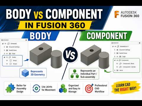
When diving into modern 3D CAD software like Autodesk Fusion 360, one of the first major hurdles beginners encounter is understanding the difference between a Body and a Component. While both represent 3D geometry on your screen, treating them as interchangeable is a common mistake that can derail your design workflow later on.

Let's break down these core concepts with practical examples so you can structure your models with confidence.

What is a Body?

In Fusion 360, a Body is a single, continuous 3D solid or surface object. Think of a body as a lump of clay or a solid block of material. You can extrude, cut, combine, and fillet bodies to build complex physical geometry.

However, bodies have strict structural limitations: - They cannot have motion joints applied directly to them. - They do not possess their own independent coordinate system (origin). - They are best suited for initial modeling steps, single-part designs, or temporary geometric tools.

What is a Component?

A Component is a self-contained organizational unit that holds geometry (bodies), sketches, construction planes, and its own unique origin. If a body is a single piece of material, a component is a complete functional part or sub-assembly.

Key features of components include: - Joints and Motion: Components can be moved relative to each other using joints to simulate real-world mechanical motion. - Assembly Structure: Components appear as distinct items in Bills of Materials (BOM) and technical drawings. - Reusability: You can create multiple instances of a component; editing one automatically updates all other instances.

Key Differences at a Glance

To streamline your 3D CAD workflow, keep these distinctions in mind: 1. Motion & Mechanics: Need your parts to articulate or move? You must use components to apply joints. 2. Drawings & Metadata: Creating detailed assembly documentation? Only components carry distinct part numbers and metadata. 3. Hierarchy: Bodies reside inside components. A component can contain multiple bodies, but a body cannot contain a component.

Best Practice: The Golden Rule

A great rule of thumb in Fusion 360 is to create a new component before you start sketching whenever you are designing a multi-part assembly. This habit keeps your browser tree organized, avoids timeline errors, and builds a professional 3D CAD design structure from the very beginning.

By mastering when to use bodies versus components, you'll create cleaner, more flexible, and fully functional 3D models every time!

3D CAD
Continue Reading | ความคิดเห็น

From 3D CAD to Reality: How 3D Printing Accelerates Product Development

Monday, August 17, 2026

In today’s fast-paced market, the ability to rapidly iterate on a design is what separates successful brands from the rest. The journey from a conceptual sketch to a tangible, functional product used to take months of back-and-forth with manufacturers. However, the integration of additive manufacturing has revolutionized this timeline, allowing designers to fail fast and innovate even faster.

The Foundation: Starting with 3D CAD

Before a single layer of material is printed, every great product begins in a digital environment. Using 3D CAD (Computer-Aided Design) software, engineers and designers can visualize complex geometries, test mechanical fitments, and ensure that every component works in harmony. This digital blueprint serves as the essential roadmap; without a precise model, the transition to a physical prototype would be impossible.

Choosing the Right 3D Printing Technology

Once your 3D CAD model is finalized, the next step is selecting the printing technology that best suits your goals. Not all 3D printers are created equal, and the choice depends on whether you need a visual model or a functional part:

  • FDM (Fused Deposition Modeling): The most common and cost-effective method, ideal for basic form testing and durable, low-cost structural parts.
  • SLA (Stereolithography): This technology uses a resin and a laser to create incredibly high-detail prototypes with smooth surface finishes, perfect for consumer electronics and jewelry.
  • SLS (Selective Laser Sintering): Utilizing a powder bed, SLS produces functional, end-use parts with high strength and heat resistance, often used for industrial applications.

Bridging the Gap to Production

3D printing bridges the gap between a digital file and a functional prototype. By utilizing 3D CAD data to create physical samples in-house, companies can identify design flaws early in the cycle, saving thousands of dollars in potential tooling costs. This iterative process allows for real-world testing, ergonomic evaluation, and stakeholder feedback long before the final production run.

Whether you are an individual inventor or part of a large engineering team, understanding the synergy between digital design and 3D printing is the key to turning your next big idea into a reality. By mastering these tools, you can ensure your product development process is as efficient and cost-effective as possible.

3D CAD
Continue Reading | ความคิดเห็น

Popular Posts Today

 
Support : 3Dcadbrowser | Grabcad | 3Dcontentcentral | D | E | F | G
Copyright © 2028. Engineering 3DCad Appication - All Rights Reserved