Cad 3D Category

Showing posts with label AutoCAD Tips. Show all posts

Boost Your Efficiency in 3D CAD: The Power of AutoCAD's Stretch Command

Saturday, September 5, 2026
In the fast-paced world of digital design, drafting efficiency is everything. Whether you are an architect, engineer, or student mastering 3D CAD software, learning how to streamline your workflow can save you hours of tedious editing. One of the most underrated yet powerful tools in AutoCAD is the STRETCH command—a feature that seamlessly combines the actions of both 'Move' and 'Extend' into a single, effortless operation.

Why the Stretch Command is a Game-Changer

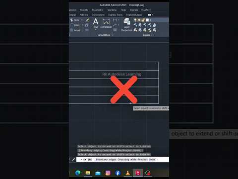
Traditionally, modifying a drawing or design element involves multiple steps. If you need to lengthen a section of a component, you might find yourself moving a boundary line first and then using the 'Extend' command to bridge the remaining gap. This repetitive process disrupts your creative flow and slows down project delivery.

The STRETCH command solves this problem instantly. By using an intelligent selection method, it moves chosen vertices while extending connected geometry simultaneously. This dual functionality allows 3D CAD professionals and 2D drafters alike to modify complex drawings with surgical precision in half the time.

How It Works: Combining Move and Extend

To execute the STRETCH command effectively, the secret lies in how you select your objects:

  1. Activate the Command: Type STRETCH (or the shortcut S) into the command line and press Enter.
  2. Use a Crossing Window: Click and drag a crossing selection box from right to left (the green selection window). Ensure you enclose the endpoints or vertices you want to move, while crossing the line segments you want to stretch.
  3. Specify a Base Point: Click a base point in your workspace to begin the movement.
  4. Perform the Action: Drag your cursor in the desired direction or input an exact dimension for exact placement.

As you drag the base point, the selected endpoints move to the new location, while the crossing lines automatically extend or contract to stay connected.

Elevate Your Design Workflow

Incorporating smart command shortcuts into your daily routine drastically improves overall modeling productivity. Instead of constantly switching between basic editing functions, utilizing the combined power of STRETCH lets you maintain focus on precision and design innovation. Apply this simple trick to your next 3D CAD or drafting project to experience a cleaner, faster design workflow!

Continue Reading | ความคิดเห็น

Precision Design: How to Clean Up Extra Lines in AutoCAD and 3D CAD Projects

Friday, September 4, 2026

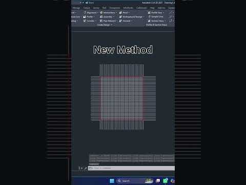
Precision is the name of the game when it comes to technical drafting. Whether you are working on a simple 2D floor plan or a complex 3D CAD model, stray lines can clutter your workspace and lead to costly errors. Learning how to efficiently remove these unwanted elements is a fundamental skill that separates amateur hobbyists from professional designers.

Why Line Management Matters

Keeping your drawing "clean" isn't just about aesthetics; it is about data integrity. In the world of professional engineering, extra lines can interfere with object snapping, bloat your file sizes, and cause significant confusion during the rendering phase. If you plan to export your 2D geometry into a more robust 3D CAD environment for extrusion or assembly, those tiny overlapping lines can prevent surfaces from closing properly, resulting in broken geometry that is difficult to fix later.

Essential Commands: Erase and Trim

The most straightforward way to remove an object is the ERASE command (shortcut: E). Simply select the line and hit enter. However, you often don't want to delete an entire entity, but rather a segment that extends too far beyond an intersection. This is where the TRIM command (shortcut: TR) becomes your most valuable tool.

In modern versions of AutoCAD, the Trim tool features a "Quick Mode" by default. This allows you to simply click or "fence" across any line segment to remove it instantly without needing to manually select cutting edges first. For those working on intricate 3D CAD layouts, holding the Shift key while using the Trim command allows you to instantly toggle to the EXTEND command, making it a versatile workflow for cleaning up messy intersections on the fly.

Using the Overkill Command for a Perfect Finish

Sometimes, extra lines aren't visible because they are hidden directly on top of each other. These "duplicate" lines are a common headache in drafting. To solve this, use the OVERKILL command. This powerful tool searches your entire workspace and automatically deletes overlapping or redundant geometry.

By mastering these simple deletion and trimming techniques, you ensure that your projects remain lightweight, professional, and ready for any advanced design stage. Whether you are a student or a seasoned pro, a clean drawing is the foundation of a successful project.

Continue Reading | ความคิดเห็น

Master AutoCAD: How to Quickly Delete Extra Lines in 3D CAD Projects

A cluttered drawing canvas can slow down your design workflow, waste system resources, and lead to frustrating modeling errors. Whether you are drafting simple 2D schematics or preparing precise geometry for complex 3D CAD models, keeping your linework clean and organized is an essential skill for every designer and engineer.

In this quick guide, we will explore the most efficient ways to delete unwanted or extra lines in AutoCAD using simple, high-speed commands.

Essential Commands for Quick Line Deletion

When working on a detailed layout, you will frequently encounter stray line segments that need to be trimmed or completely removed. Here are the primary tools to get the job done:

  1. The TRIM Command (Shortcut: TR) The TRIM tool is ideal when you want to snip off sections of a line that extend past an intersection without removing the whole object.
  2. How to use it: Type TR and press Enter. In modern AutoCAD versions, simply click or drag across any line segment you wish to trim away.

  3. The ERASE Command (Shortcut: E) If a line is completely redundant, trimming it piece-by-piece is inefficient.

  4. How to use it: Select the unwanted lines with your cursor and press Delete, or type E and press Enter to erase them instantly.

Advanced Cleanup: Eliminating Overlapping Lines

Extra lines are not always visible at first glance—sometimes duplicate geometry sits directly underneath your visible drawing. Overlapping geometry can create major headache when converting 2D sketches into a solid 3D CAD shape.

To clear hidden duplicates, use the powerful OVERKILL command: * Type OVERKILL into the command line and press Enter. * Select your entire drawing or specific target objects. * Adjust the settings in the dialogue window to automatically join collinear lines and delete duplicate objects.

Final Thoughts

Mastering these core line-deletion techniques will dramatically increase your drafting speed and overall drawing accuracy. Maintaining clean, duplicate-free linework from the start ensures seamless transitions into advanced 3D CAD workflows. Apply these tips to your next AutoCAD project to keep your workspace tidy and efficient!

3D CAD
Continue Reading | ความคิดเห็น

Mastering Precision: How to Separate Polyline Segments in 3D CAD

Wednesday, September 2, 2026

In the world of digital drafting and modeling, efficiency is just as important as accuracy. One of the most common entities you will encounter when working with professional design software is the polyline—a connected sequence of segments created as a single object. While polylines are incredibly useful for maintaining continuity in a design, there are many instances where you need to isolate or separate a single line from the group.

Whether you are cleaning up a floor plan or preparing a complex geometric shape for a 3D CAD project, knowing how to manipulate these lines is a fundamental skill. In this guide, we will explore the most effective ways to separate polyline segments without losing your design’s integrity.

Why Separate Polylines?

When working within a 3D CAD environment, you might find that a single polyline is preventing you from applying specific offsets, extrusions, or fillets to just one part of your model. By breaking the polyline into individual segments, you gain granular control over your geometry. This allows for more detailed editing, such as changing the layer, color, or thickness of just one specific section of what was previously a unified shape.

The "Explode" vs. "Break" Method

There are two primary ways to handle this task depending on your specific needs:

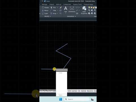
  1. The Explode Command: If you need to turn the entire polyline into individual, independent lines, the "EXPLODE" command is your quickest option. Simply select the polyline, type EXPLODE (or X), and press enter. Every segment will now be its own entity.
  2. The Edit Polyline (PEDIT) Method: If you only want to remove or disconnect one specific segment while keeping the rest of the polyline intact, the PEDIT command is superior. Within this tool, you can use the "Break" option. This allows you to select two points on the polyline to create a gap, effectively separating the segments at a precise location.

Optimizing Your Workflow

Mastering these small but vital techniques significantly speeds up the drafting process. For those specializing in 3D CAD, maintaining a clean workspace by properly managing polylines ensures that your 3D models are built on a solid, error-free 2D foundation.

By understanding how to bridge the gap between unified shapes and individual segments, you can approach complex architectural or engineering tasks with much greater confidence. Start practicing these commands today to take your CAD skills to the next level!

3D CAD
Continue Reading | ความคิดเห็น

Master AutoCAD Polar Array: Create Precise Circular Patterns in 3D CAD

Wednesday, August 19, 2026

Designing symmetrical parts and mechanical components does not have to be a tedious, repetitive process. Whether you are drafting basic 2D gears, flange hole patterns, or intricate architectural features, mastering the AutoCAD Polar Array tool is an absolute game-changer. It allows designers to duplicate objects around a central axis instantly, saving valuable drafting time while ensuring mathematical precision.

What is the AutoCAD Polar Array Tool?

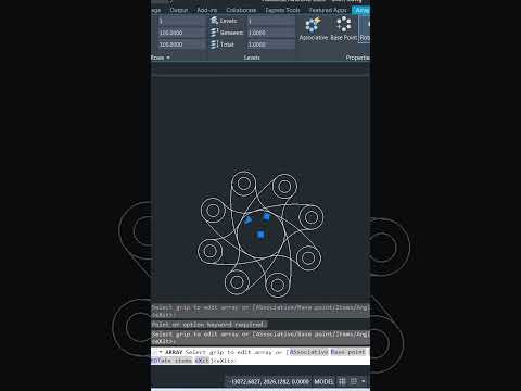
The Polar Array command automatically distributes copies of selected objects in a circular pattern around a specified center point. Instead of manually copying and rotating individual elements—a method prone to cumulative degree errors—the array tool calculates exact spacing and angles dynamically.

How to Create Perfect Circular Patterns Fast

Creating a polar array in AutoCAD is fast and intuitive. Follow these simple steps:

  1. Select the Object: Type ARRAYPOLAR in the command line (or choose the Polar Array icon from the Modify panel) and pick the geometry you want to repeat.
  2. Specify the Center Point: Click the precise central axis point around which your objects should rotate.
  3. Adjust the Settings: Use the contextual ribbon tab to set the total number of items, fill angle (such as 360 degrees for a full circle), and row count.
  4. Close the Array: Review the dynamic real-time preview and click Close Array to finalize your pattern.

Elevating Efficiency in Modern 3D CAD Workflows

While polar arrays are a staple of 2D drafting, they play a vital role when transitioning your concepts into robust 3D CAD modeling environments. Precision at the initial sketch stage directly impacts the success of subsequent 3D operations, such as extruding circular bolt patterns, lofting complex geometries, or building rotational assemblies.

By utilizing dynamic associative arrays, you can easily tweak object counts or radial dimensions at any point later in your design pipeline. Integrating these smart circular patterns into your daily 3D CAD workflow eliminates guesswork, drastically minimizes drawing errors, and accelerates your overall project delivery. Give the polar array command a try on your next project to instantly boost your drafting productivity!

3D CAD
Continue Reading | ความคิดเห็น

Popular Posts Today

 
Support : 3Dcadbrowser | Grabcad | 3Dcontentcentral | D | E | F | G
Copyright © 2028. Engineering 3DCad Appication - All Rights Reserved