Cad 3D Category

Showing posts with label Design Workflow. Show all posts

Mastering Advanced Sketching: Pro Tips and Tricks for CAD Software Users

Sunday, September 13, 2026
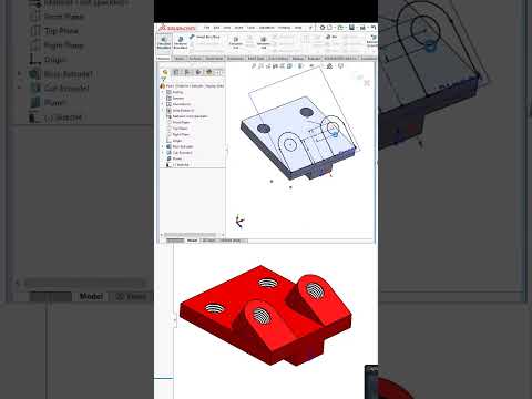
Sketching is the fundamental building block of any 3D model. Whether you are designing a simple bracket or a complex mechanical assembly, the efficiency and stability of your final product depend heavily on how you approach the initial 2D layout. For professionals and hobbyists alike, mastering the nuances of your CAD software is the secret to moving from basic designs to high-level engineering.

Rethinking Your Sketching Strategy

Many users fall into the habit of using the same basic tools for every project. However, advanced sketching is about more than just drawing lines and circles; it is about intent and flexibility. Instead of manually dimensioning every single entity, advanced users leverage geometric relations to define how shapes interact. By "thinking a different way," you can create sketches that are easier to modify later, preventing your model from "breaking" when a single dimension changes.

Efficiency Through Advanced Techniques

When working with professional-grade CAD software, speed is often just as important as accuracy. One of the best ways to improve your workflow is to utilize shortcut keys and mouse gestures for common sketch entities. Furthermore, exploring non-traditional methods—such as using construction geometry to drive complex patterns or employing the "Path Length" dimension—can solve design challenges that standard sketching simply cannot handle.

Another "pro tip" involves minimizing the number of entities in a single sketch. By breaking complex parts into several simpler features, you maintain better control over the design intent. This modular approach is a hallmark of an expert user who knows how to harness the full potential of their digital tools.

Why Mastering These Skills Matters

The transition from a beginner to an advanced user requires a shift in mindset. It’s about understanding the underlying logic of the program. By mastering these advanced tips and tricks, you aren't just drawing; you are programmatically defining a physical object.

As you continue to refine your skills within your CAD software, you will find that your design process becomes more intuitive and significantly faster. This not only makes you a more valuable engineer or designer but also allows you to focus more on the creative aspects of innovation rather than the technical hurdles of the interface. Keep experimenting with different sketching methods, and you will soon see a massive improvement in your 3D modeling precision.

Continue Reading | ความคิดเห็น

Mastering Precision: How to Separate Polyline Segments in 3D CAD

Wednesday, September 2, 2026

In the world of digital drafting and modeling, efficiency is just as important as accuracy. One of the most common entities you will encounter when working with professional design software is the polyline—a connected sequence of segments created as a single object. While polylines are incredibly useful for maintaining continuity in a design, there are many instances where you need to isolate or separate a single line from the group.

Whether you are cleaning up a floor plan or preparing a complex geometric shape for a 3D CAD project, knowing how to manipulate these lines is a fundamental skill. In this guide, we will explore the most effective ways to separate polyline segments without losing your design’s integrity.

Why Separate Polylines?

When working within a 3D CAD environment, you might find that a single polyline is preventing you from applying specific offsets, extrusions, or fillets to just one part of your model. By breaking the polyline into individual segments, you gain granular control over your geometry. This allows for more detailed editing, such as changing the layer, color, or thickness of just one specific section of what was previously a unified shape.

The "Explode" vs. "Break" Method

There are two primary ways to handle this task depending on your specific needs:

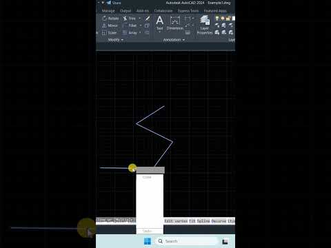
  1. The Explode Command: If you need to turn the entire polyline into individual, independent lines, the "EXPLODE" command is your quickest option. Simply select the polyline, type EXPLODE (or X), and press enter. Every segment will now be its own entity.
  2. The Edit Polyline (PEDIT) Method: If you only want to remove or disconnect one specific segment while keeping the rest of the polyline intact, the PEDIT command is superior. Within this tool, you can use the "Break" option. This allows you to select two points on the polyline to create a gap, effectively separating the segments at a precise location.

Optimizing Your Workflow

Mastering these small but vital techniques significantly speeds up the drafting process. For those specializing in 3D CAD, maintaining a clean workspace by properly managing polylines ensures that your 3D models are built on a solid, error-free 2D foundation.

By understanding how to bridge the gap between unified shapes and individual segments, you can approach complex architectural or engineering tasks with much greater confidence. Start practicing these commands today to take your CAD skills to the next level!

3D CAD
Continue Reading | ความคิดเห็น

Popular Posts Today

 
Support : 3Dcadbrowser | Grabcad | 3Dcontentcentral | D | E | F | G
Copyright © 2028. Engineering 3DCad Appication - All Rights Reserved