
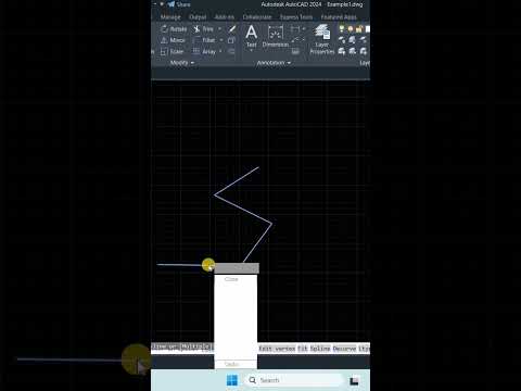
In the world of digital drafting and modeling, efficiency is just as important as accuracy. One of the most common entities you will encounter when working with professional design software is the polyline—a connected sequence of segments created as a single object. While polylines are incredibly useful for maintaining continuity in a design, there are many instances where you need to isolate or separate a single line from the group.
Whether you are cleaning up a floor plan or preparing a complex geometric shape for a 3D CAD project, knowing how to manipulate these lines is a fundamental skill. In this guide, we will explore the most effective ways to separate polyline segments without losing your design’s integrity.
Why Separate Polylines?
When working within a 3D CAD environment, you might find that a single polyline is preventing you from applying specific offsets, extrusions, or fillets to just one part of your model. By breaking the polyline into individual segments, you gain granular control over your geometry. This allows for more detailed editing, such as changing the layer, color, or thickness of just one specific section of what was previously a unified shape.
The "Explode" vs. "Break" Method
There are two primary ways to handle this task depending on your specific needs:
- The Explode Command: If you need to turn the entire polyline into individual, independent lines, the "EXPLODE" command is your quickest option. Simply select the polyline, type
EXPLODE(orX), and press enter. Every segment will now be its own entity. - The Edit Polyline (PEDIT) Method: If you only want to remove or disconnect one specific segment while keeping the rest of the polyline intact, the
PEDITcommand is superior. Within this tool, you can use the "Break" option. This allows you to select two points on the polyline to create a gap, effectively separating the segments at a precise location.
Optimizing Your Workflow
Mastering these small but vital techniques significantly speeds up the drafting process. For those specializing in 3D CAD, maintaining a clean workspace by properly managing polylines ensures that your 3D models are built on a solid, error-free 2D foundation.
By understanding how to bridge the gap between unified shapes and individual segments, you can approach complex architectural or engineering tasks with much greater confidence. Start practicing these commands today to take your CAD skills to the next level!

