
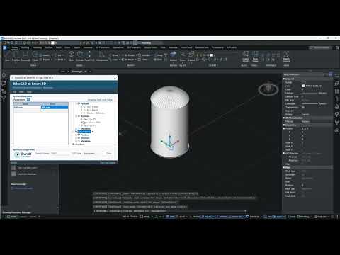
In the world of industrial plant design, speed, precision, and software interoperability are crucial. Combining the robust drafting capabilities of BricsCAD with the industry-standard execution of Intergraph Smart 3D offers engineers an unbeatably efficient modeling workflow.
If you want to streamline your equipment creation process, learning how to build and deploy intelligent models between these platforms is key. Here is a practical overview of how to build a vertical vessel symbol in BricsCAD and export it straight into Smart 3D.
Step 1: Designing a Parametric Vertical Vessel in BricsCAD
Creating custom equipment shapes from scratch for every project can be time-consuming. However, by leveraging parametric modeling techniques within BricsCAD, designers can define flexible geometric constraints and dimensional parameters for complex components like Vertical Vessels.
Instead of redrawing equipment whenever project specifications change, a single dynamic model can adapt to varying heights, diameters, and nozzle placements instantly. BricsCAD provides an intuitive environment for setting up these rules, ensuring your 3D models remain versatile and easy to update.
Step 2: Seamless Integration into Intergraph Smart 3D
Once your vessel symbol is configured, the next step is deploying it into Intergraph Smart 3D. Traditional file conversions often lead to lost metadata or static, non-editable shapes.
Fortunately, direct deployment methodologies allow you to transfer the component while preserving its intelligence. By importing your parametric symbols directly into Smart 3D's catalog environment, your engineering team gains access to rich equipment assets ready for piping, layout, and structural placement without starting from scratch.
Key Benefits for Plant Design Workflows
Integrating BricsCAD dynamic symbols into your Smart 3D ecosystem delivers several immediate advantages: * Enhanced Efficiency: Utilizing parametric components eliminates repetitive modeling tasks, saving hours of manual labor. * Data Consistency: Assets retain vital dimensional data and connection attributes needed for downstream piping workflows. * Design Flexibility: Quick adjustments can be made at any stage of the detailed engineering phase without compromising project timelines.
Final Thoughts
Bridging the gap between preliminary CAD design and comprehensive plant execution doesn't have to be complicated. By mastering the workflow from BricsCAD to Intergraph Smart 3D, you empower your engineering team with scalable, intelligent equipment symbols that boost productivity across every project.
