
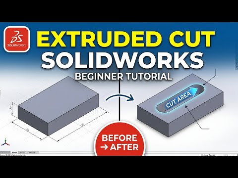
Navigating the world of 3D CAD design can feel overwhelming at first, but mastering core tools in SOLIDWORKS is the best way to build a solid foundation. One of the most essential features every designer needs to learn early on is the Extruded Cut tool. Whether you are creating simple mounting holes or complex custom pockets in a model, understanding how to subtract material efficiently is crucial for successful digital prototyping.
In this step-by-step guide, we will walk you through everything you need to know to confidently use the Extruded Cut feature in SOLIDWORKS.
What is the Extruded Cut Feature?
In 3D CAD modeling, while an Extruded Boss/Base adds material to a part, an Extruded Cut does the exact opposite: it removes material. It takes a 2D profile sketched on a flat face or plane and projects it through a solid body to cut away shape geometry.
Step-by-Step Guide to Using Extruded Cut
Follow these simple steps to perform your first extruded cut:
- Select a Face and Create a Sketch: Click on the flat surface of your 3D model where you want to remove material. Open a new Sketch and draw your desired 2D shape (such as a circle for a bolt hole or a rectangle for a slot).
- Activate the Extruded Cut Tool: With your 2D sketch active, switch to the Features tab on the CommandManager and click Extruded Cut.
- Set the End Condition: In the PropertyManager on the left, select how deep you want the cut to extend:
- Blind: Specify an exact depth dimension.
- Through All: Cuts completely through the entire object regardless of thickness.
- Up To Next: Cuts until it reaches the next surface encountered.
- Confirm the Cut: Click the green checkmark to apply the feature. Your model will instantly update with the cut-out shape!
Essential Tips for Beginners
To elevate your proficiency in 3D CAD software, always consider your "design intent" when choosing end conditions. Using dynamic options like Through All or Up To Surface ensures your cut automatically adjusts if you change the thickness of your original part later.
By mastering this fundamental technique, you will streamline your workflow and unlock endless possibilities in your 3D modeling projects. Grab your software, start practicing, and take your design skills to the next level!
