
In the rapidly evolving world of mechanical engineering, the ability to transform a conceptual 2D sketch into a functional, three-dimensional model is a critical skill. Whether you are a student or a seasoned professional, mastering 3D CAD software is essential for staying competitive in the design industry. In this guide, we will explore the foundational techniques used to create a mechanical mounting bracket, a common component found in various industrial applications.
Understanding the Component: The Mounting Bracket
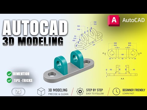
The project focuses on a 3D mechanical mounting bracket, a vital piece of hardware used to secure components in place. The design features a long, rounded rectangular base plate, which provides stability and a solid surface for attachment. This specific model serves as an excellent practice piece because it combines basic geometric shapes with precise technical requirements.
By focusing on the base plate first, designers can learn how to manage fillets (rounded corners) and ensure that the proportions are accurate before moving on to more complex features. Precision is the cornerstone of mechanical design, and practicing with these foundational shapes builds the necessary muscle memory for larger projects.
The 3D CAD Modeling Workflow
To create this bracket, the modeling process typically begins with a 2D profile. Using 3D CAD tools, the designer draws the footprint of the bracket, ensuring that the dimensions for the length and width are exact. Once the 2D sketch is finalized, the "Extrude" command is used to give the bracket its thickness.
Key steps in this workflow include: 1. Sketching the Base: Creating the rectangular profile with rounded ends. 2. Adding Mounting Holes: Positioning two mounting holes accurately to ensure the bracket can be bolted to a surface. 3. Applying 3D Transforms: Using subtraction or union tools to finalize the mechanical structure.
Why Practice Matters
Mechanical practice work, such as modeling this mounting bracket, is about more than just learning software buttons; it is about understanding spatial relationships and manufacturing constraints. Utilizing 3D CAD allows you to visualize potential interference issues and material thickness before a single part is ever manufactured.
As you continue your journey in AutoCAD and 3D modeling, remember that consistency is key. Exercises like these prepare you for complex assemblies, helping you bridge the gap between a simple idea and a professional-grade mechanical component.
