Cad 3D Category

Showing posts with label AutoCAD. Show all posts

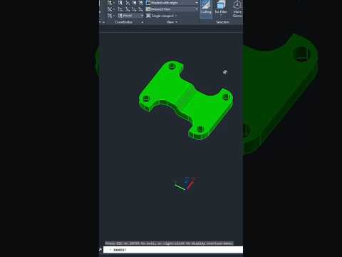
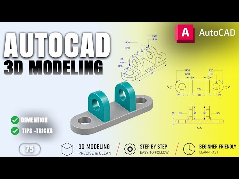
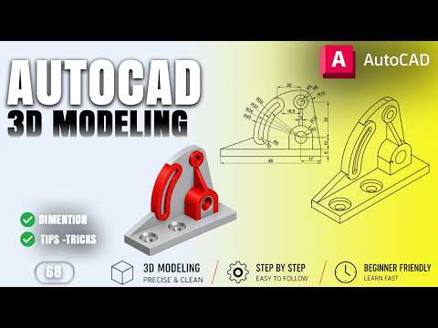
Mastering AutoCAD: How to Convert a 2D Engineering Drawing into a 3D Model

Sunday, September 27, 2026
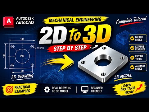
In the world of mechanical design and manufacturing, transforming a flat concept into a realistic spatial visualization is a fundamental skill. AutoCAD remains one of the premier software tools for turning a preliminary engineering drawing into a functional 3D object. Whether you are a mechanical engineering student or an aspiring CAD technician, learning how to seamlessly bridge the gap between 2D drafting and 3D modeling will dramatically enhance your workflow and design capabilities.

Step 1: Preparing Your 2D Layout in AutoCAD

Every successful 3D model begins with an accurate 2D foundation. Before jumping into extrusions and solid modeling, you must establish precise geometry on your drawing plane:

  • Establish Base Geometry: Draw the main profile of your component (such as an Auto Guide) using precise dimensions and coordinates.
  • Clean Up Boundaries: Trim unnecessary overlapping lines, close any open loops, and convert individual line segments into unified poly-lines using the JOIN command or create a single REGION.
  • Verify Precision: A clean and mathematically precise 2D engineering drawing prevents geometry errors during the 3D conversion process, ensuring seamless extrusions later on.

Step 2: Transitioning to the 3D Modeling Environment

Once your 2D geometric profiles are properly prepared and joined, it is time to shift your workspace from 2D Drafting & Annotation to 3D Modeling:

  • Change View Angles: Switch your viewport to a 3D perspective, such as SW Isometric, and set your visual style to Shaded or Conceptual for better depth perception.
  • Utilize Extrude and Presspull: Select your closed 2D shapes and apply commands like EXTRUDE or PRESSPULL to give height and volume to your base profiles.
  • Apply Boolean Operations: Combine different shapes or create cuts (such as mounting holes or internal slots) using the UNION and SUBTRACT tools to achieve the final mechanical shape.

Conclusion

Mastering the transition from a 2D engineering drawing to a detailed 3D model is essential for modern product design and mechanical prototyping. By following a structured step-by-step approach in AutoCAD, you can efficiently transform complex flat schematics into highly accurate 3D models ready for analysis, presentation, or manufacturing.

Continue Reading | ความคิดเห็น

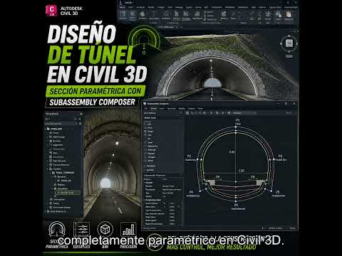
Mastering Tunnel Design: A Step-by-Step Guide Using 3D CAD and Civil 3D

Saturday, September 12, 2026

Designing a tunnel is often considered one of the most complex challenges in the fields of civil engineering and surveying. From managing underground clearances to ensuring structural integrity, the process demands an incredibly high level of precision. Fortunately, modern 3D CAD technology has revolutionized how we approach these projects. By utilizing Autodesk Civil 3D, engineers can transform complex data into accurate, data-rich models that streamline the entire construction workflow.

Defining the Path: Alignments and Profiles

The first step in any tunnel project within a 3D CAD environment is establishing a precise horizontal alignment and vertical profile. In Civil 3D, this involves more than just drawing lines; it is about creating a dynamic path that reflects the existing terrain and the specific depth requirements of the underground structure. These parameters serve as the backbone of your model, ensuring that every subsequent step—from structural modeling to volume calculations—is anchored to an accurate geometric reference.

The Power of Assemblies in Tunneling

What truly sets tunnel design apart from standard road design is the "Assembly." In Civil 3D, the assembly represents the cross-section of your tunnel. This includes the structural lining, waterproofing layers, and internal infrastructure such as ventilation, lighting, and drainage systems. Utilizing advanced 3D CAD tools allows you to customize these subassemblies to fit various shapes—whether you are designing a circular TBM (Tunnel Boring Machine) section, a horseshoe shape, or a rectangular box culvert. This flexibility is crucial for adapting to different geological conditions and specific engineering requirements.

Generating the Corridor and Final Visualization

Once the alignment, profile, and assembly are finalized, you can generate the "Corridor." This is the stage where your tunnel design truly comes to life in a three-dimensional space. The corridor integrates all your design data to create a comprehensive model that can be used for cross-section extraction, material takeoff, and clash detection.

By visualizing the tunnel within a professional 3D CAD framework, you can identify potential design flaws or utility conflicts long before the construction phase begins. Mastering these workflows in Civil 3D not only improves your efficiency as a designer but also ensures the highest level of accuracy for large-scale infrastructure projects. Whether you are a seasoned surveyor or a civil engineering student, learning these steps is essential for staying competitive in the modern industry.

Continue Reading | ความคิดเห็น

Unlocking the Power of 3D CAD: Quick AutoCAD Tricks Every Designer Should Know

Friday, September 11, 2026

In today’s fast-paced engineering and architectural industries, digital drafting is no longer just about 2D lines and basic shapes. Mastering 3D CAD software like AutoCAD has become an essential skill for professionals looking to bring complex ideas to life with precision and speed. Whether you are a beginner or a seasoned designer, optimizing your workflow can make a massive difference in your daily productivity.

Why 3D CAD Skills Matter in Modern Design

Transitioning from traditional 2D drafting to 3D CAD modeling opens up endless possibilities. It allows designers to visualize spatial relationships, detect structural errors early in the planning phase, and produce photo-realistic renders for clients. Beyond aesthetics, working in three dimensions ensures greater accuracy, making project handoffs smoother across multidisciplinary teams.

Essential AutoCAD Productivity Hacks

To create stunning models efficiently, you don't just need knowledge—you need speed. Here are a few quick tips to streamline your AutoCAD workflow:

  • Utilize Key Command Shortcuts: Relying on keyboard shortcuts like EXT (Extrude), PRESSPULL, and UNION saves valuable time compared to navigating menu icons manually.
  • Master Visual Styles: Switch seamlessly between Conceptual, Shaded, and Realistic views to inspect your model's geometry without slowing down system performance.
  • Implement Dynamic Blocks: Create parametric components that can be resized or altered quickly without redrawing elements from scratch.
  • Use the ViewCube Efficiently: Navigate your workspace effortlessly by customizing your ViewCube settings for fast orientation and angle adjustments.

Elevate Your Design Potential

Integrating these quick habits into your daily routine will drastically reduce drafting time while improving the quality of your output. As 3D CAD technology continues to evolve, staying updated with efficient modeling techniques will keep you ahead of the curve in the competitive design landscape. Start practicing these tricks today and transform your AutoCAD project workflow!

Continue Reading | ความคิดเห็น

Master 3D CAD: The Ultimate Professional Upgrade Guide for AutoCAD Users

Thursday, September 10, 2026

Transitioning from traditional 2D drafting to modern 3D CAD modeling is one of the most impactful upgrades a design professional can make. While 2D drawings have served as the industry standard for decades, today’s complex engineering and architectural demands require greater clarity, precision, and efficiency. Elevating your skills to three dimensions isn't just a technical upgrade—it is a major business advantage.

Why Upgrade from 2D to 3D Design?

Making the jump to 3D modeling fundamentally transforms how you deliver projects. Unlike flat, two-dimensional plans, three-dimensional models offer an immersive view of your design, allowing you to identify spatial conflicts, design flaws, and structural errors long before construction or manufacturing begins.

Key business benefits include: - Enhanced Visualization: Communicate your design intent clearly to clients and non-technical stakeholders who may struggle to interpret 2D schematics. - Fewer Costly Errors: Automated clash detection drastically reduces rework on the job site or shop floor. - Faster Revisions: Updating a single 3D component automatically reflects across all associated views, drawings, and documentation.

Essential Steps for a Seamless Transition

Moving from 2D lines and polylines to solid geometry requires a shift in how you conceptualize your work. Here is how to make the upgrade as smooth as possible:

  1. Shift Your Conceptual Mindset: Stop thinking in terms of separate flat views (Plan, Elevation, Section) and start building objects as unified, solid components.
  2. Master Navigation and the UCS: Get comfortable orbiting around objects and manipulating the User Coordinate System (UCS). Understanding workplanes is crucial for precise placement in a three-dimensional space.
  3. Start with Basic Primitives: Begin by creating simple shapes like boxes, cylinders, and extrusions. Once you master combining these simple solids, you can advance to more complex parametric features.

Unlocking the Full Potential of 3D CAD

Adopting a robust 3D CAD workflow allows you to extract precise 2D documentation, generate photorealistic renderings, and produce accurate bills of materials—all from a single source model. By investing the time to upgrade your AutoCAD skill set, you position yourself and your firm at the forefront of modern design, delivering superior quality while saving time and resources.

Continue Reading | ความคิดเห็น

From 2D Drafting to 3D CAD: The Professional’s Guide to Modern Modeling

In the competitive world of design and engineering, the shift from traditional 2D drafting to a robust 3D CAD environment is no longer just an optional skill—it is a business necessity. While AutoCAD has long been the gold standard for precision floor plans and technical schematics, upgrading your workflow to three dimensions can fundamentally change how you communicate ideas and deliver value to your clients.

The Business Case for Dimensional Depth

The primary advantage of moving beyond flat lines is the ability to visualize spatial relationships with absolute clarity. When you utilize 3D CAD software, you are essentially building a virtual prototype rather than just drawing a representation of one. This allows for early-stage clash detection, more accurate material estimation, and significantly more persuasive client presentations. Instead of asking a stakeholder to imagine the scale of a project through a flat blueprint, you can offer them a realistic digital walkthrough.

Boosting Precision and Efficiency

Transitioning to 3D doesn't mean discarding your 2D roots. In fact, professional-grade modeling often starts with a 2D sketch or foundation. However, the true power lies in the automation that three-dimensional environments provide. In a modern workflow, updates made to a model can automatically propagate through all associated elevations, sections, and schedules. This drastically reduces the manual labor associated with revisions and ensures that your documentation remains consistent across the board. By spending less time on manual updates, your team can focus more on design innovation.

Bridging the Professional Gap

Making the upgrade requires a strategic shift in mindset. You are moving from thinking in lines and arcs to thinking in volumes and surfaces. By integrating 3D CAD into your daily professional practice, you position yourself as a forward-thinking expert capable of handling the complexities of modern architecture, manufacturing, and engineering projects. While the learning curve may seem steep initially, the long-term return on investment in project clarity and delivery speed is undeniable. Now is the time to transform your flat drawings into immersive, functional models that set your business apart.

Continue Reading | ความคิดเห็น

Unlock the Power of 3D CAD: How to Use AutoCAD’s INTERSECT Command

Wednesday, September 9, 2026

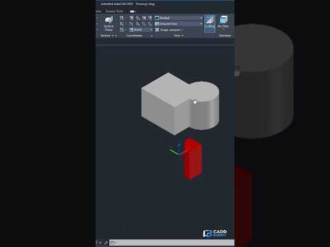
Creating complex models in modern design often requires combining basic shapes into intricate geometry. If you are working on modern 3D CAD projects in AutoCAD, knowing how to efficiently extract overlapping volumes is essential. Enter the INTERSECT command—a fundamental Boolean operation that dramatically streamlines your digital modeling workflow.

Understanding the AutoCAD INTERSECT Command

The INTERSECT command allows you to combine two or more existing 3D solids, surfaces, or 2D regions, generating a single new object from their shared volume or area. Instead of spending time manually trimming or reshaping geometry, INTERSECT automatically deletes all non-overlapping portions and preserves only the common intersection.

How to Use the INTERSECT Command Step-by-Step

Using this tool in AutoCAD is straightforward and intuitive:

  1. Prepare Your Geometry: Ensure that two or more 3D solids or 2D regions overlap each other in your drawing area.
  2. Activate the Command: Type INTERSECT (or its shortcut IN) in the command line and press Enter.
  3. Select Objects: Click on all the overlapping objects you wish to intersect.
  4. Complete the Action: Press Enter to execute the command.

In an instant, AutoCAD discards everything outside the overlapping zone, leaving behind only the newly formed solid or surface.

Pro-Tip: Ensure your objects actually intersect in three-dimensional space. If objects only appear to overlap visually in a 2D viewport but are separated along the Z-axis, the command will not generate a result.

Why INTERSECT is Essential for 3D CAD Modeling

Integrating Boolean commands into your 3D CAD workflow saves considerable design time. Whether you are drafting mechanical parts, architectural features, or complex industrial components, the INTERSECT tool guarantees absolute mathematical precision without tedious manual editing.

By mastering INTERSECT alongside complementary commands like UNION and SUBTRACT, any 3D CAD user can quickly transform basic geometric primitives into sophisticated, production-ready 3D models. Try it in your next AutoCAD session to speed up your modeling process!

Continue Reading | ความคิดเห็น

9mm Luger Cartridge 3D CAD Model | Multi-Format Download

Preview Image

Download a high-precision 3D CAD model of the standard 9mm Luger (9x19mm Parabellum) cartridge. Designed for mechanical engineers, defense designers, and CAD specialists who require accurate geometry for clearance testing, dynamic assemblies, visualization, and product design.

Key Features & Software Compatibility:

  • Broad File Format Support: Fully compatible with SolidWorks, AutoCAD, Autodesk Inventor, PTC Creo, CATIA, Siemens NX, and ACIS-supported software.
  • Precision Modeling: Scaled according to standard 9mm Luger dimensions for realistic rendering and mechanical fit.
  • Versatile Applications: Ideal for firearm accessory design, holster engineering, educational graphics, and ballistics simulations.

Enhance your technical project workflow by downloading this reliable 3D CAD asset today.


Continue Reading | ความคิดเห็น

Mastering Mechanical Design: A Step-by-Step Guide to 3D CAD Modeling for Mounting Brackets

In the rapidly evolving world of mechanical engineering, the ability to transform a conceptual 2D sketch into a functional, three-dimensional model is a critical skill. Whether you are a student or a seasoned professional, mastering 3D CAD software is essential for staying competitive in the design industry. In this guide, we will explore the foundational techniques used to create a mechanical mounting bracket, a common component found in various industrial applications.

Understanding the Component: The Mounting Bracket

The project focuses on a 3D mechanical mounting bracket, a vital piece of hardware used to secure components in place. The design features a long, rounded rectangular base plate, which provides stability and a solid surface for attachment. This specific model serves as an excellent practice piece because it combines basic geometric shapes with precise technical requirements.

By focusing on the base plate first, designers can learn how to manage fillets (rounded corners) and ensure that the proportions are accurate before moving on to more complex features. Precision is the cornerstone of mechanical design, and practicing with these foundational shapes builds the necessary muscle memory for larger projects.

The 3D CAD Modeling Workflow

To create this bracket, the modeling process typically begins with a 2D profile. Using 3D CAD tools, the designer draws the footprint of the bracket, ensuring that the dimensions for the length and width are exact. Once the 2D sketch is finalized, the "Extrude" command is used to give the bracket its thickness.

Key steps in this workflow include: 1. Sketching the Base: Creating the rectangular profile with rounded ends. 2. Adding Mounting Holes: Positioning two mounting holes accurately to ensure the bracket can be bolted to a surface. 3. Applying 3D Transforms: Using subtraction or union tools to finalize the mechanical structure.

Why Practice Matters

Mechanical practice work, such as modeling this mounting bracket, is about more than just learning software buttons; it is about understanding spatial relationships and manufacturing constraints. Utilizing 3D CAD allows you to visualize potential interference issues and material thickness before a single part is ever manufactured.

As you continue your journey in AutoCAD and 3D modeling, remember that consistency is key. Exercises like these prepare you for complex assemblies, helping you bridge the gap between a simple idea and a professional-grade mechanical component.

Continue Reading | ความคิดเห็น

Master AutoCAD: A Step-by-Step Guide to 3D CAD Modeling

Transitioning from traditional 2D drafting to the dynamic world of digital design can seem intimidating, but learning 3D CAD is one of the most rewarding skills for students, engineers, and designers alike. Whether you are completing a practical class assignment or building a professional design portfolio, creating three-dimensional figures is an essential step in modern CAD mastery.

In this guide, we will break down the core process of transforming simple concepts into fully realized solid models using AutoCAD.

Setting Up Your 3D Workspace

Before creating any object, you need to prepare your design environment. Switch your workspace from the standard "2D Drafting & Annotation" mode to "3D Modeling." This change gives you direct access to powerful modeling tools, such as solid primitives, extrusion features, and Boolean commands.

When working in a 3D CAD environment, dynamic navigation is critical. Learn to use the ViewCube and Navigation Bar to orbit around your workspace smoothly. Viewing your project from multiple angles ensures accurate alignment along the X, Y, and Z axes.

Key Steps to Construct a 3D Figure

Building a complex 3D figure typically follows a simple, structured workflow:

  1. Draw the 2D Outline: Start by creating a accurate 2D base profile using closed polylines. A clean 2D sketch forms the foundation of any solid model.
  2. Extrude or Presspull: Convert your flat sketch into a solid shape by giving it height. Use the Extrude or Presspull tool to extend the geometry along the Z-axis.
  3. Refine with Boolean Operations: Combine different shapes using the Union tool, or create cutouts, holes, and slots using the Subtract command.

Tips for an Efficient Workflow

To keep your design process smooth and organized, implement these quick tips: - Organize with Layers: Keep your original 2D construction lines, solid models, and annotations on separate layers. - Toggle Visual Styles: Switch between "2D Wireframe" for precise snapping and "Shaded with Edges" to preview your final 3D figure. - Practice with Hands-On Tasks: The fastest way to learn is by following practical tutorials and recreating real-world mechanical parts or geometric shapes.

By mastering these fundamental techniques, you will be well on your way to creating accurate, professional-grade models in 3D CAD. Open your software, try out these steps, and bring your designs to life today!

Continue Reading | ความคิดเห็น

How to Use the AutoCAD INTERSECT Command for Efficient 3D CAD Modeling

Tuesday, September 8, 2026

Creating complex shapes and geometry in modern design software doesn't have to be a slow, tedious process. If you are working on a 3D CAD project in AutoCAD, mastering Boolean operations can drastically speed up your modeling workflow. One of the most powerful yet straightforward tools in this set is the INTERSECT command.

What is the INTERSECT Command in AutoCAD?

The INTERSECT command allows you to combine two or more overlapping 3D solids or 2D regions to create a brand-new object. Instead of manually trimming lines or calculating complex angles, AutoCAD evaluates the overlapping volume of your selected shapes, deletes the surrounding non-overlapping portions, and leaves you with the exact shared geometric core.

Step-by-Step Guide to Using the INTERSECT Command

Using this feature is quick and intuitive. Follow these simple steps to isolate common areas easily:

  1. Create Overlapping Objects: Draw two or more overlapping 3D solids (such as a cylinder passing through a cube) or 2D regions on your workspace.
  2. Activate the Command: Type INTERSECT (or the keyboard shortcut IN) into the command line and press Enter.
  3. Select Your Objects: Click on all the overlapping objects you want to calculate the shared area for.
  4. Finalize the Operation: Press Enter. AutoCAD instantly removes the surrounding geometry, keeping only the intersecting shape.

Why Include INTERSECT in Your Design Workflow?

Boolean tools like Union, Subtract, and Intersect form the foundation of professional 3D CAD modeling. Integrating the INTERSECT tool into your daily drafting routine offers several key advantages:

  • Time Efficiency: Generate intricate, custom shapes in seconds without having to rebuild complex boundaries from scratch.
  • High Precision: Eliminate human error when finding the exact overlapping boundaries of curved or angled solids.
  • Design Versatility: Ideal for creating mechanical parts, custom architectural joints, and specialized industrial components.

Conclusion

Understanding how to extract common areas using the INTERSECT command is an essential skill for anyone looking to optimize their 3D CAD productivity. Try experimenting with different overlapping shapes in AutoCAD today to see how much time this practical feature can save you on your next design project!

Continue Reading | ความคิดเห็น

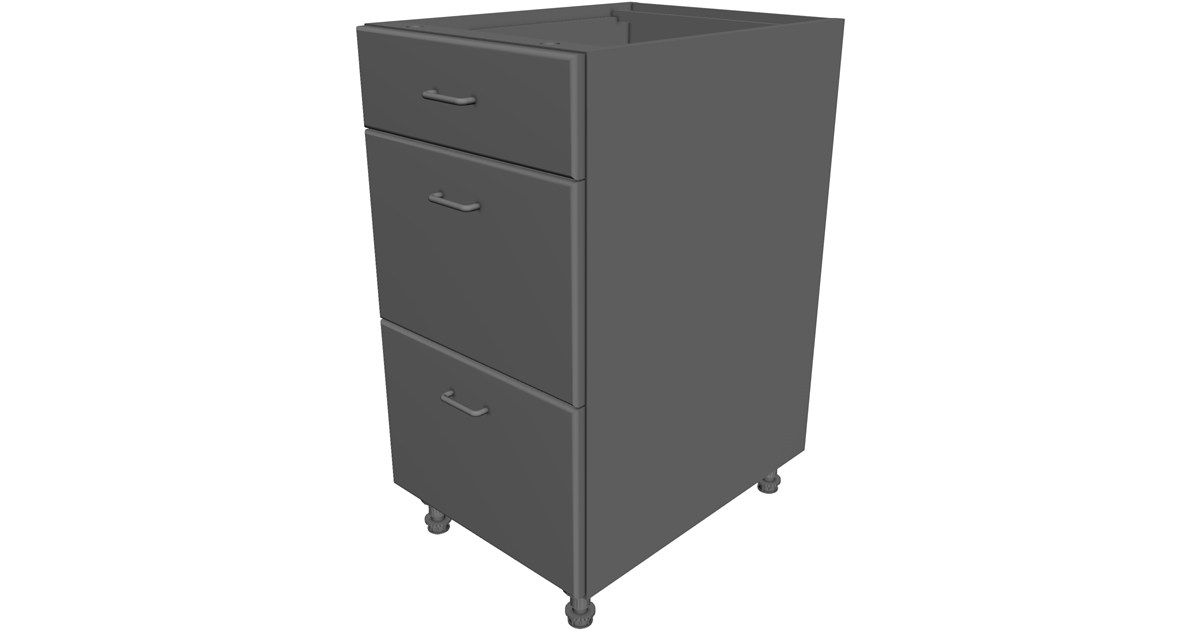
Download 3 Drawer Cabinet CAD Model (SolidWorks, AutoCAD & STEP)

Friday, September 4, 2026

Preview ImagePreview ImagePreview Image

Enhance your interior rendering, office layouts, and industrial storage projects with this high-quality 3 Drawer Cabinet CAD Model. Engineered for seamless integration across all major 3D design software, this model helps designers and engineers save valuable modeling time.

Key Highlights & Compatibility:

  • Universal Software Support: Ready to use in AutoCAD, SolidWorks, Autodesk Inventor, PTC Creo, Siemens NX, CATIA, ACIS, and more.
  • Multiple File Formats: Available in standard parametric and mesh formats for easy importing.
  • Versatile Application: Perfect for architectural visualization, workshop equipment design, and office space planning.

Download this 3D cabinet model today and optimize your CAD workflow.


Continue Reading | ความคิดเห็น

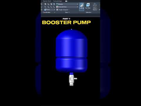
Mastering Mechanical Design: A Step-by-Step Guide to 3D CAD Booster Pump Assembly

Mechanical engineering and industrial design have been revolutionized by the power of digital modeling. If you have ever wondered how complex machinery, such as a high-performance booster pump, is constructed from the ground up, you are in the right place. In this first installment of our series, we dive deep into the technical process of building a booster pump assembly component by component.

The Foundation of Industrial Modeling

A booster pump is a vital piece of equipment used to increase the pressure of fluids in various systems, from residential water lines to massive industrial cooling towers. Modeling such a device requires a high level of precision and a systematic approach. By utilizing 3D CAD software, designers can create a digital twin of the pump, allowing them to test fitments, check tolerances, and visualize the final product before a single piece of metal is ever cast.

Precision Component Creation

The assembly process begins with the individual parts. In Part 1 of our guide, we focus on the foundational elements, such as the pump housing and the base plate. Using AutoCAD’s robust toolset, we transition from simple 2D sketches into complex three-dimensional geometries. This stage involves utilizing commands like Extrude, Revolve, and Sweep to give volume to our technical drawings.

The beauty of working within a 3D CAD environment is the ability to maintain absolute accuracy. Whether you are defining the diameter of a flange or the curvature of an impeller blade, the software ensures that every measurement is mathematically sound. This meticulous attention to detail is what separates a hobbyist from a professional designer.

Why Mastering Assembly Matters

Understanding how to assemble parts is just as important as knowing how to draw them. In this series, we don't just look at parts in isolation; we look at how they interact. We explore the constraints and alignments necessary to ensure that the motor, shaft, and housing align perfectly.

Developing these skills in 3D CAD is essential for anyone looking to excel in the fields of manufacturing or architecture. By following along with this booster pump project, you will gain a practical understanding of spatial relationships and mechanical constraints.

Stay tuned for the next part of this series, where we will continue to add complexity to our assembly, moving one step closer to a fully functional mechanical model. Whether you are a student or a seasoned pro, there is always something new to learn in the world of 3D design.

Continue Reading | ความคิดเห็น

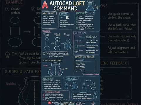
2D to 3D Made Easy: Mastering the AutoCAD PRESSPULL Command for 3D CAD

In the fast-paced world of digital design, the ability to transition quickly from a flat sketch to a complex model is a vital skill. If you are looking to excel in 3D CAD, understanding the tools that bridge the gap between 2D drafting and 3D visualization is essential. One of the most powerful and time-saving features available to designers today is the AutoCAD PRESSPULL command.

What Makes PRESSPULL So Powerful?

While many beginners rely solely on the "Extrude" command, the PRESSPULL tool offers a much more dynamic and versatile approach. It allows you to select a bounded area—even if it is not a closed polyline—and instantly pull it into the third dimension. This versatility makes it a cornerstone for anyone looking to streamline their workflow in 3D CAD.

Beyond just adding volume, PRESSPULL is dual-purpose. It can be used to subtract material by pushing a shape into an existing solid, making it an incredibly efficient tool for creating holes, slots, or recessed features without needing complex Boolean operations.

Step-by-Step: From 2D to 3D in Seconds

Mastering this command is straightforward. Follow these steps to speed up your modeling process: 1. Initialize the Command: Type PRESSPULL in the command line or select the icon from the Modeling tab. 2. Select the Area: Hover your cursor over the 2D shape or a bounded internal area. AutoCAD will automatically highlight the detected space. 3. Define the Height: Click and drag your mouse upward to add height, or move it inward to cut through a solid. 4. Precision Entry: For exact engineering specifications, simply type in the desired numerical value and hit Enter.

Why It Changes Your Workflow

Efficiency is the ultimate goal when working on complex 3D CAD projects. The PRESSPULL command eliminates the tedious step of joining individual lines into regions or polylines before they can be transformed. It intelligently recognizes internal boundaries, allowing you to create architectural walls with window cutouts or mechanical parts with pre-drilled holes in just a few clicks.

By incorporating this simple shortcut into your daily routine, you can significantly reduce your modeling time and focus more on the creative aspects of your design. Whether you are a beginner or a seasoned professional, the PRESSPULL command is a must-know feature that makes 3D modeling feel like second nature.

Continue Reading | ความคิดเห็น

Master Interference Checking in AutoCAD: A Guide to Flawless 3D CAD Modeling

Wednesday, September 2, 2026

When working on complex engineering or architectural designs, precision is everything. A single overlapping component can lead to costly errors during fabrication or construction. If you rely on AutoCAD for your 3D CAD projects, detecting spatial conflicts early is essential to maintaining model accuracy. Fortunately, AutoCAD features a powerful built-in tool specifically designed for clash detection: the INTERFERE command.

What is the INTERFERE Command in AutoCAD?

The INTERFERE command allows users to compare sets of 3D solid objects to check if they overlap or occupy the same physical space. Unlike standard Boolean operations such as SUBTRACT or UNION, which permanently alter your geometry, INTERFERE highlights overlapping volumes by generating temporary 3D solids. This lets you inspect and resolve design collisions without modifying your original components.

Step-by-Step: How to Perform an Interference Check

Running an interference check in AutoCAD is straightforward and fast:

  1. Activate the Command: Type INTERFERE into the command line and press Enter.
  2. Select First Object Set: Select the first group of 3D solids you want to check, then press Enter.
  3. Select Second Object Set: Choose the second set of 3D solids to compare against the first (or press Enter again to check for interferences among the first set alone).
  4. Review Results: AutoCAD opens the Interference Checking dialog box and temporarily highlights any overlapping geometry in red.
  5. Manage Clashes: Cycle through each interference point, zoom into specific conflict areas, and choose whether to delete or keep the generated interference solids for reference.

Why Clash Detection Matters for Your Workflow

Integrating regular clash detection into your 3D CAD workflow offers several key advantages:

  • Prevents Manufacturing Errors: Spotting physical overlaps early ensures components fit together seamlessly during actual assembly.
  • Saves Time and Money: Identifying errors during drafting takes seconds, whereas fixing mistakes on the shop floor or construction site is expensive and time-consuming.
  • Improves Model Quality: Clean geometry yields accurate mass property calculations, faster rendering, and seamless exports.

Mastering the INTERFERE command is one of the easiest ways to elevate the quality of your 3D CAD designs. Incorporate this quick check into your routine to ensure your 3D models are accurate, professional, and conflict-free!

3D CAD
Continue Reading | ความคิดเห็น

Mastering 3D CAD: How to Use the AutoCAD UNION Command to Combine Solids

Friday, August 28, 2026

When working in modern 3D CAD software like AutoCAD, creating complex shapes often starts with combining simpler geometry. Whether you are designing mechanical parts, architectural elements, or intricate 3D models, knowing how to merge distinct objects into a single continuous solid is a fundamental skill.

That is where the UNION command comes in. In this guide, we will break down how the UNION command works and how you can use it to streamline your 3D modeling workflow.

What is the UNION Command in AutoCAD?

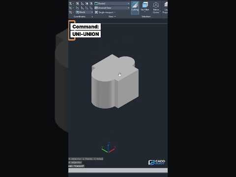
The UNION command in AutoCAD is a Boolean operation used to combine two or more overlapping or adjacent 3D solids, surfaces, or 2D regions into a single, unified object. Instead of managing dozens of individual shapes, UNION allows you to merge them so they act as one single piece.

This is essential for clean geometric design, accurate volume calculations, and preparing models for 3D printing or rendering.

Step-by-Step: How to Combine 3D Objects Using UNION

Combining 3D solids in AutoCAD is straightforward once you know the basic steps:

  1. Prepare Your Geometry: Place two or more 3D solid objects (such as boxes, cylinders, or spheres) so that they intersect or touch each other.
  2. Activate the Command: Type UNION (or UNI) in the command line and press Enter. Alternatively, click the Union tool located on the Solid Editing panel under the 3D Modeling workspace tab.
  3. Select Objects: Click on all the 3D solids you wish to combine. You can select them one by one or use a selection window.
  4. Execute: Press Enter or Spacebar to complete the operation.

Instantly, the intersecting inner lines between the objects will disappear, leaving you with one seamless 3D object.

Why the UNION Command is Essential for 3D CAD Professionals

Mastering Boolean operations like UNION drastically improves your efficiency when working on complex projects. Here are a few key benefits:

  • Simpler Object Management: Moving, rotating, or scaling a single merged object is much easier than selecting multiple separate components.
  • Clean Exporting: Many 3D printing and rendering tools require a watertight, unified mesh to process files correctly.
  • Improved Performance: Reducing the overall object count keeps your drawing files lighter and smoother to navigate.

Whether you are just getting started with 3D CAD or looking to sharpen your existing modeling skills, mastering the UNION command is a crucial step toward creating professional-grade 3D designs. Give it a try in your next AutoCAD project!

3D CAD
Continue Reading | ความคิดเห็น

Essential 3D CAD Practice: How to Model a Mechanical Mounting Bracket

Thursday, August 20, 2026

Designing mechanical components requires precision, efficiency, and a solid grasp of core modeling tools. Whether you are an aspiring mechanical engineer or a seasoned draftsman looking to sharpen your skills, practicing real-world component design is the best way to improve. In this guide, we explore how to create a detailed mechanical mounting bracket, offering an ideal exercise to strengthen your 3D CAD abilities.

Fundamental Tools for 3D Mechanical Modeling

Building complex mechanical parts in AutoCAD relies on mastering a few fundamental 3D commands. A mounting bracket, for instance, tests your ability to combine base shapes, create precise cutouts, and align geometries effectively.

Key operations featured in this practice exercise include: - Extrude: Transforming 2D cross-sections into 3D solid objects. - Subtract: Removing internal geometries to create mounting holes, counterbores, and slots. - Presspull: Dynamically modifying faces and extruding bounded areas for rapid design iteration. - Union: Combining multiple distinct solids into a unified, single component.

By understanding how these tools interact, you can approach even the most intricate mechanical blueprints with clarity and confidence.

Step-by-Step Approach to the Bracket Design

To begin modeling the bracket, start by establishing the primary 2D profile. Accuracy at this stage is critical, as any dimensional error in the base sketch will carry over to the final 3D model.

  1. Draft the Base Profile: Draw the foundational 2D outline of the bracket using accurate dimensions and centerlines.
  2. Convert to 3D Solids: Apply the EXTRUDE or PRESSPULL command to add depth to the base plate and upright support structures.
  3. Incorporate Feature Cutouts: Utilize boolean operations like SUBTRACT to carve out bolt mounting holes and center clearance slots.
  4. Refine and Inspect: Apply fillets or chamfers to sharp edges to optimize structural integrity, then switch visual styles to inspect your solid model from multiple angles.

Elevate Your Mechanical Design Skills

Mastering modern 3D CAD workflows isn't just about learning software commands; it is about developing a structured, logical approach to 3D spatial problem-solving. Completing practical hands-on exercises helps bridge the gap between theoretical knowledge and workplace execution.

Take time to work through this mechanical mounting bracket exercise, experiment with varied dimensions, and continue building your proficiency in 3D CAD modeling today!

3D CAD
Continue Reading | ความคิดเห็น

Master 3D CAD Modeling: AutoCAD Complete Tutorial Series Part 3

Tuesday, August 18, 2026

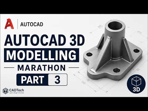
Are you ready to take your digital design skills to the next level? Welcome to Part 3 of our complete AutoCAD tutorial series, where we continue our deep dive into the world of spatial design. Whether you are an aspiring mechanical engineer, an architect, or a product designer, mastering modern 3D CAD software is an essential step toward turning your creative concepts into precise, real-world models.

Deepening Your 3D Modeling Expertise

In this third installment of our modeling marathon, we transition from basic geometric shapes into more complex solid modeling techniques. Understanding how to navigate a 3-dimensional workspace requires a solid grasp of User Coordinate Systems (UCS), dynamic viewports, and visual styles. This tutorial breaks down these fundamental concepts into manageable, easy-to-follow steps so you can design with clarity and confidence.

Core Tools and Techniques Covered

To build complex structures efficiently, you need to master AutoCAD's core 3D toolset. In this lesson, you will explore key features including:

  • Extrude and Presspull: Learn how to instantly transform flat 2D sketches into robust 3D solids.
  • Revolve and Sweep: Discover how to generate intricate rotational designs and path-based geometries effortlessly.
  • Boolean Operations: Combine, subtract, and intersect primary shapes to create sophisticated components with maximum accuracy.

By practicing these essential operations, you will significantly enhance your 3D CAD workflow and reduce drafting errors in complex engineering projects.

Streamlining Your Workflow from 2D to 3D

One of the biggest challenges designers face is shifting their technical mindset from traditional 2D drafting to a multi-dimensional spatial environment. Part 3 focuses heavily on practical exercises designed to bridge this exact gap. You will learn essential keyboard shortcuts, strategic layer management, and practical visualization tips that dramatically speed up your production time without sacrificing detail.

Step Up Your Design Skills Today

Mastering complex software takes practice, but following structured, hands-on tutorials accelerates your learning curve. Implementing these step-by-step methods will give you the confidence to tackle real-world drafting challenges in any professional 3D CAD environment. Watch the complete video guide, follow along with the exercises, and continue building your expertise today!

3D CAD
Continue Reading | ความคิดเห็น

Popular Posts Today

 
Support : 3Dcadbrowser | Grabcad | 3Dcontentcentral | D | E | F | G
Copyright © 2028. Engineering 3DCad Appication - All Rights Reserved