Cad 3D Category

Showing posts with label Mechanical Engineering. Show all posts

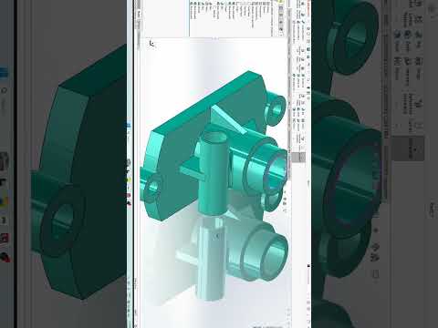
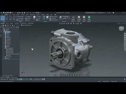
Mastering Mechanical Design: A Deep Dive into 3D CAD with SolidWorks (Day 49)

Sunday, October 25, 2026
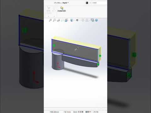
In the rapidly evolving world of industrial design, the ability to transform a conceptual sketch into a functional mechanical component is a vital skill. For many engineers and designers, the journey toward mastery is paved with consistent practice and the right tools. As we reach "Day 49" of our design challenge, we shift our focus toward the intricate details of machine part modeling, showcasing why SolidWorks remains the gold standard for professionals worldwide.

The Power of Precision with 3D CAD

Modern engineering demands more than just aesthetic appeal; it requires mathematical precision and structural integrity. Using 3D CAD software allows designers to simulate real-world conditions, test tolerances, and visualize complex assemblies before a single piece of hardware is ever manufactured. This digital-first approach significantly reduces production costs and accelerates the time-to-market for new machinery.

In today’s project, we explore the nuances of parametric modeling. By defining specific constraints and relationships between different geometric features, we create a robust model that can be easily updated or modified. Whether you are designing a simple bracket or a complex engine component, mastering these 3D CAD techniques ensures that your designs are both scalable and accurate.

Progressing Through the Day 49 Milestone

Reaching the halfway point of a 100-day challenge is a significant milestone. At this stage, the focus shifts from basic sketching to advanced features such as swept bosses, lofted cuts, and complex fillets. The "Day 49" model highlights the intersection of form and function, focusing on a machine part that requires specific load-bearing properties.

As you navigate through the SolidWorks interface, you begin to realize that the software is not just a drawing tool—it is an extension of the engineer's mind. Every extrude and revolve operation is a step toward solving a mechanical puzzle. For those looking to transition from a hobbyist to a professional level, consistently practicing with 3D CAD is the most effective way to build the muscle memory required for high-speed, high-accuracy modeling.

Conclusion: Elevate Your Design Workflow

The journey of a thousand models begins with a single sketch. By committing to a daily practice routine, you not only learn the software but also develop a deeper understanding of mechanical geometry. As we continue to push the boundaries of what is possible in the digital workspace, staying updated with the latest tools and techniques is essential for any aspiring designer.

Stay tuned as we continue this journey toward day 100, refining our skills and unlocking the full potential of industrial-grade modeling software.

Continue Reading | ความคิดเห็น

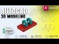
Mastering 3D CAD: How to Model a Mechanical Mounting Bracket in AutoCAD

Friday, September 11, 2026

In the evolving world of mechanical engineering, the ability to transform a 2D concept into a functional 3D model is an essential skill. One of the best ways to sharpen these skills is through practical, hands-on exercises that replicate real-world components. In this guide, we explore the process of creating a mechanical mounting bracket, a fundamental tool in the world of 3D CAD.

Starting with the Foundation: The Base Plate

Every great mechanical model begins with a solid foundation. For this mounting bracket project, we start by constructing a rectangular base plate. In AutoCAD, this involves using primitive shapes or extruding a 2D rectangle to a specific thickness. By assigning a distinct color—such as a vibrant red—designers can easily differentiate between various components within a complex assembly. This level of visual clarity is one of the many advantages of using professional 3D CAD software for mechanical practice.

Precision Engineering and Mounting Holes

A mounting bracket is only as functional as its connectivity. The next critical step in the modeling process is the addition of four precise mounting holes located at the corners of the base. This requires careful measurement and the use of the "Subtract" command to create clean, accurate voids. This stage of the project emphasizes the importance of geometric constraints and precision, ensuring that the digital part would theoretically fit perfectly into a real-world mechanical assembly.

Why Practice Work is Essential

Whether you are a student or an aspiring engineer, consistent practice is the key to proficiency. Transitioning from basic shapes to complex mechanical parts helps users understand the workspace, the Z-axis, and the various shortcuts that speed up the design process. Utilizing 3D CAD for these practice sessions allows you to experiment with different materials, lighting, and viewing angles before moving on to more intricate industrial designs.

Conclusion

Modeling a mechanical mounting bracket is more than just a basic exercise; it is a stepping stone to mastering industrial design. By following these fundamental principles in AutoCAD, you can build a strong portfolio of mechanical parts and gain the confidence needed to tackle large-scale engineering projects. Keep practicing, keep designing, and unlock the full potential of your technical creativity!

Continue Reading | ความคิดเห็น

9mm Luger Cartridge 3D CAD Model | Multi-Format Download

Wednesday, September 9, 2026

Preview Image

Download a high-precision 3D CAD model of the standard 9mm Luger (9x19mm Parabellum) cartridge. Designed for mechanical engineers, defense designers, and CAD specialists who require accurate geometry for clearance testing, dynamic assemblies, visualization, and product design.

Key Features & Software Compatibility:

  • Broad File Format Support: Fully compatible with SolidWorks, AutoCAD, Autodesk Inventor, PTC Creo, CATIA, Siemens NX, and ACIS-supported software.
  • Precision Modeling: Scaled according to standard 9mm Luger dimensions for realistic rendering and mechanical fit.
  • Versatile Applications: Ideal for firearm accessory design, holster engineering, educational graphics, and ballistics simulations.

Enhance your technical project workflow by downloading this reliable 3D CAD asset today.


Continue Reading | ความคิดเห็น

Mastering SolidWorks: A Beginner’s Guide to 3D CAD for Complex Mechanical Parts

Sunday, September 6, 2026

From Basic Sketches to Complex Mechanical Designs

Transitioning from simple 2D sketches to intricate 3D models can feel overwhelming for newcomers. However, mastering essential skills in modern 3D CAD software like SolidWorks opens up endless possibilities for engineers, product designers, and makers alike. Whether you are designing industrial machinery, automotive components, or custom mechanical parts, understanding how to properly structure your modeling workflow is the secret to creating clean, professional designs.

Key Steps to Modeling Complex Mechanical Components

When tackling an intricate mechanical part in SolidWorks, breaking the design down into basic geometric features makes the process manageable. Here is the proven step-by-step approach:

  1. Establish a Strong Base Sketch: Always start on a primary plane (Front, Top, or Right). Focus on creating accurate profile lines and ensure your initial sketch is fully defined using precise dimensions and geometric relations.
  2. Build the Primary Geometry: Convert your 2D sketches into solid 3D shapes using core features such as Boss-Extrude, Revolve, or Loft. For complex parts, adding material incrementally gives you maximum control over the model structure.
  3. Add Secondary Cutouts and Features: Use Extruded Cuts, Revolved Cuts, and the Hole Wizard to create functional features like internal cavities, thread locations, and keyways.
  4. Apply Finishing Touches: Round sharp edges and smooth out stress points by adding Fillets and Chamfers. Applying these features at the very end keeps your model's performance smooth and responsive.

Best Practices for 3D CAD Beginners

Building complex parts requires more than just knowing where the buttons are; it demands smart modeling habits. For anyone starting out, mastering 3D CAD tools requires strategic planning. Always keep your FeatureManager design tree organized and logically structured. Renaming key features and keeping sketches simple will save you hours of troubleshooting whenever design modifications are required later in the project.

Take Your Engineering Skills to the Next Level

With consistent practice, constructing detailed 3D mechanical components will naturally become second nature. By following hands-on practical exercises and building complex parts step-by-step, you will gain the confidence needed to turn your engineering ideas into precise, production-ready digital models and elevate your overall 3D CAD skills to the next level.

Continue Reading | ความคิดเห็น

3-Axis Linear Module CAD Model | Free Multi-Format Download

Saturday, September 5, 2026

Preview Image

Accelerate your mechanical design process with this high-precision 3-Axis Linear Module CAD Model. Perfect for industrial automation, robotics, gantry systems, and CNC machinery, this versatile 3D assembly provides detailed geometry and accurate mounting references for Cartesian positioning systems.

Key Features & Details:

  • System Type: 3-Axis (X-Y-Z) Linear Motion Assembly / Cartesian Module.
  • Applications: Ideal for pick-and-place mechanisms, automated inspection systems, CNC tooling, and custom industrial machinery.
  • Software Compatibility: Fully compatible with AutoCAD, SolidWorks, Autodesk Inventor, PTC Creo, CATIA, Siemens NX, ProE, ACIS, STEP, and IGES.
  • Time-Saving: Pre-modeled assembly ready for direct integration into your larger mechanical layouts.

Download this essential linear actuator CAD model today to streamline your structural design and prototyping workflow.


Continue Reading | ความคิดเห็น

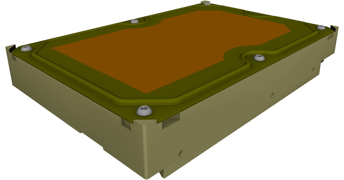
3.5-Inch SATA Hard Drive 3D CAD Model Free Download

Preview Image

Accelerate your mechanical design process with this precision 3.5-inch SATA Hard Disk Drive (HDD) CAD Model. Ideal for computer chassis planning, server rack design, custom enclosure development, and electronic hardware layout.

Key Features & Specifications:

  • Standard Form Factor: Exact exterior dimensions and mounting hole placements compliant with standard 3.5" drive specifications.
  • SATA Interface Detail: Accurately rendered SATA power and data connector positioning for precise backplane/cable routing.
  • Multi-Format Support: Fully compatible with leading 3D software platforms.

Supported CAD Packages:

Importable into SolidWorks, Autodesk Inventor, AutoCAD, PTC Creo, Siemens NX, CATIA, ACIS, and universal formats like STEP/IGES.


Continue Reading | ความคิดเห็น

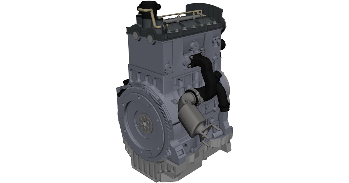
3 Cylinder Engine CAD Model | Free Multi-Format Download

Friday, September 4, 2026

Preview ImagePreview ImagePreview Image

Unlock a comprehensive 3 Cylinder Engine CAD Model engineered for mechanical designers, automotive engineers, and CAD professionals. This detailed 3D assembly provides an authentic look into modern internal combustion engine geometry, making it ideal for simulation, rendering, and design validation.

Key Features & Technical Specifications:

  • Detailed Mechanical Assembly: Includes core components such as the cylinder block, pistons, connecting rods, crankshaft, and valvetrain.
  • Optimized for Simulation: Perfect for performing Finite Element Analysis (FEA), Computational Fluid Dynamics (CFD), and kinematic motion studies.
  • High Precision: Accurate tolerances suitable for engineering reverse-engineering reference or educational prototyping.

Compatible CAD Packages:

This 3D model is compatible with all major parametric modeling software and neutral file formats, including:

  • SolidWorks, Autodesk Inventor, & AutoCAD
  • CATIA, PTC Creo, & Siemens NX
  • Universal formats: STEP, IGES, ACIS (SAT), and OBJ

Continue Reading | ความคิดเห็น

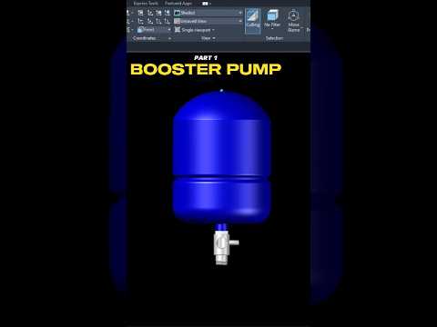
Mastering Mechanical Design: A Step-by-Step Guide to 3D CAD Booster Pump Assembly

Mechanical engineering and industrial design have been revolutionized by the power of digital modeling. If you have ever wondered how complex machinery, such as a high-performance booster pump, is constructed from the ground up, you are in the right place. In this first installment of our series, we dive deep into the technical process of building a booster pump assembly component by component.

The Foundation of Industrial Modeling

A booster pump is a vital piece of equipment used to increase the pressure of fluids in various systems, from residential water lines to massive industrial cooling towers. Modeling such a device requires a high level of precision and a systematic approach. By utilizing 3D CAD software, designers can create a digital twin of the pump, allowing them to test fitments, check tolerances, and visualize the final product before a single piece of metal is ever cast.

Precision Component Creation

The assembly process begins with the individual parts. In Part 1 of our guide, we focus on the foundational elements, such as the pump housing and the base plate. Using AutoCAD’s robust toolset, we transition from simple 2D sketches into complex three-dimensional geometries. This stage involves utilizing commands like Extrude, Revolve, and Sweep to give volume to our technical drawings.

The beauty of working within a 3D CAD environment is the ability to maintain absolute accuracy. Whether you are defining the diameter of a flange or the curvature of an impeller blade, the software ensures that every measurement is mathematically sound. This meticulous attention to detail is what separates a hobbyist from a professional designer.

Why Mastering Assembly Matters

Understanding how to assemble parts is just as important as knowing how to draw them. In this series, we don't just look at parts in isolation; we look at how they interact. We explore the constraints and alignments necessary to ensure that the motor, shaft, and housing align perfectly.

Developing these skills in 3D CAD is essential for anyone looking to excel in the fields of manufacturing or architecture. By following along with this booster pump project, you will gain a practical understanding of spatial relationships and mechanical constraints.

Stay tuned for the next part of this series, where we will continue to add complexity to our assembly, moving one step closer to a fully functional mechanical model. Whether you are a student or a seasoned pro, there is always something new to learn in the world of 3D design.

Continue Reading | ความคิดเห็น

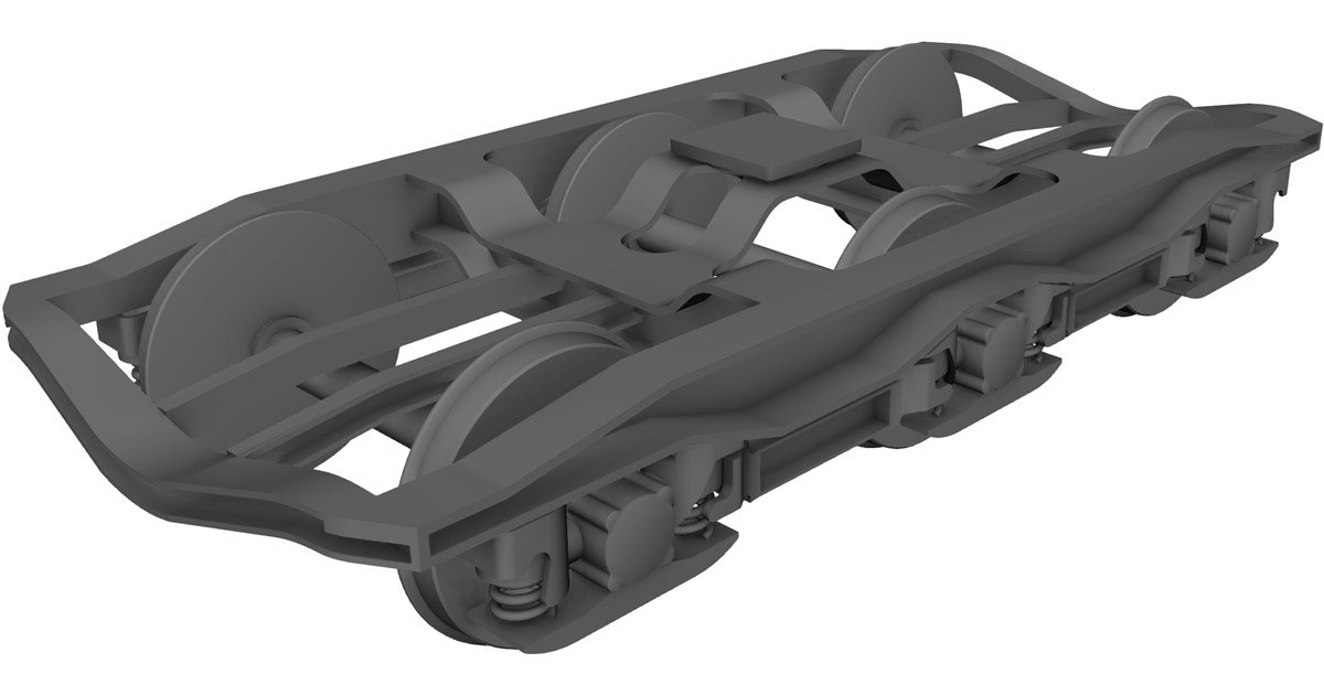
Download 3 Axle Rail Bogie 3D CAD Model (SolidWorks, CATIA, STEP)

Preview Image

Download a high-quality 3 Axle Rail Bogie CAD Model designed for heavy rail equipment, locomotive engineering, and mechanical simulations. This detailed 3D assembly model is an essential reference for engineers, designers, and students working on railway rolling stock design.

Key Features & Highlights:

  • Detailed Mechanical Assembly: Features a robust 3-axle configuration, complete wheelsets, suspension system frame, and braking assembly components.
  • Multi-Format Compatibility: Ready to use in AutoCAD, SolidWorks, Autodesk Inventor, PTC Creo, Siemens NX, CATIA, and ACIS formats.
  • Versatile Applications: Ideal for finite element analysis (FEA), dynamic simulation, vehicle integration, and academic research.

Streamline your heavy rail engineering workflow by integrating this precision 3D CAD model into your project today.


Continue Reading | ความคิดเห็น

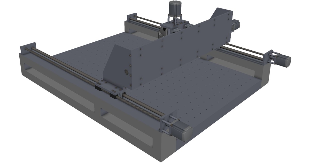
Download High-Precision 3-Axis CNC Machine CAD Model (Multi-Format)

Thursday, September 3, 2026

Preview Image

Elevate your engineering and manufacturing simulations with this highly detailed 3-Axis CNC Machine 3D CAD Model. Designed for accuracy, this model is ideal for mechanical engineers, machine designers, digital twin development, and workshop layout planning.

Key Features & Specifications

  • Detailed Geometry: Includes realistic structural assemblies, spindle mounting, linear motion guides, and frame components.
  • Multi-Software Support: Pre-formatted for seamless import into leading CAD/CAM software packages.
  • Versatile Applications: Ideal for motion simulation, toolpath collision checking, workshop floor layout design, and educational displays.

Supported CAD File Formats

This 3-axis CNC model can be integrated into your workflow using popular standard formats, including:

  • SolidWorks (.sldprt, .sldasm)
  • AutoCAD (.dwg, .dxf)
  • Autodesk Inventor (.ipt, .iam)
  • PTC Creo / Pro-ENGINEER
  • Siemens NX
  • CATIA
  • Universal/Neutral Formats: STEP, IGES, ACIS (.sat)

Download this essential 3D model today to streamline your machine design and virtual commissioning processes.


Continue Reading | ความคิดเห็น

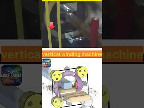
How Vertical Orbital Wrapping Machines Work: A Deep Dive into 3D CAD Engineering

In the world of modern packaging and industrial automation, vertical orbital wrapping machines play a vital role in securing products for safe transport. From long aluminum extrusions to bulky wooden panels, these mechanical systems wrap items quickly, tightly, and consistently. But have you ever wondered about the intricate mechanical movements operating beneath the surface?

By analyzing detailed 3D CAD models, we can unlock the fascinating engineering principles that make these machines so extraordinarily efficient.

Understanding the Vertical Orbital Wrapping Mechanism

A vertical orbital wrapping machine—often referred to as a ring wrapper—functions by rotating a roll of stretch film around a product as it moves horizontally through a central ring. Unlike traditional pallet wrappers, the product remains steady on a conveyor belt while the wrapping ring spins vertically around it.

This high-speed orbital rotation requires precise mechanical timing, durable bearing assemblies, and continuous tension control to ensure smooth film application without tearing or bunching.

Visualizing Mechanics Through 3D CAD

Understanding complex mechanical interactions can be difficult through 2D drawings alone. Utilizing advanced 3D CAD animations allows engineers, designers, and students to observe internal mechanics in real-time.

Through dynamic 3D modeling, you can clearly see: - Drive Systems: How rotational force is transferred from the drive motor directly to the large orbital ring. - Film Dispenser Dynamics: How pre-stretch carriage rollers optimize material usage while maintaining proper film tension. - Conveyor Synchronization: How linear product feeding aligns seamlessly with the ring's RPM for optimal wrapping coverage.

Furthermore, leveraging 3D CAD technology during the design phase enables mechanical engineers to perform motion studies, detect physical interference, and optimize components long before physical manufacturing begins.

The Value of Orbital Wrapping in Industrial Automation

Vertical orbital wrapping delivers exceptional protection against dust, moisture, and load shifting during transit. By automating this packaging stage, industrial facilities significantly boost throughput, reduce manual labor, and minimize material waste.

Whether you are a mechanical engineering enthusiast studying kinematic design or an industrial professional seeking modern packaging solutions, exploring these machines through accurate visual models offers deep insight into modern industrial automation.

3D CAD
Continue Reading | ความคิดเห็น

2-Axle Wheel Set 3D CAD Model | Multi-Format Engineering Download

Preview Image

Download a high-precision 2-Axle Wheel Set 3D CAD Model engineered for transport equipment designers, mechanical engineers, and industrial machinery developers. This structural assembly model provides an accurate geometric reference for railway bogies, heavy machinery chassis, and custom industrial carts.

Key Highlights & Engineering Features

  • Precise Geometry: Features detailed wheel hubs, axles, and mounting interfaces ready for assembly integration.
  • Simulation & Analysis Ready: Optimized for motion analysis, stress testing (FEA), and digital prototyping.
  • Multi-Platform Usability: Pre-configured for native and universal CAD environments to save design time.

Supported CAD Formats

This model is fully compatible with popular industry-standard software, including:

  • SolidWorks (.sldprt, .sldasm)
  • Autodesk Inventor (.ipt, .iam)
  • CATIA & PTC Creo / Pro-E
  • Siemens NX
  • AutoCAD & ACIS (.sat, .dwg)
  • Neutral Formats: STEP (.stp), IGES (.igs)

Continue Reading | ความคิดเห็น

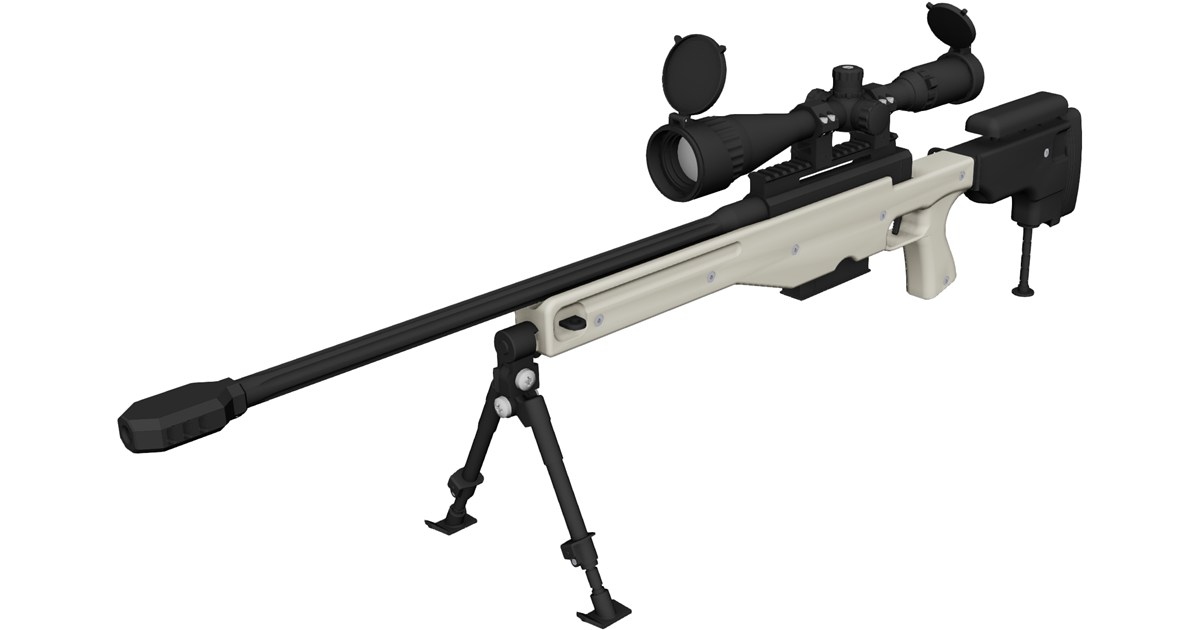
.338 Lapua Magnum Sniper Rifle 3D CAD Model | SolidWorks, CATIA & STEP

Wednesday, September 2, 2026

Preview Image

Looking for a highly detailed 3D model of the .338 Lapua Magnum Sniper Rifle for your mechanical engineering, simulation, or visualization projects? Download this precision-engineered CAD assembly ready for multi-platform integration.

Key Features:

  • Accurate Mechanical Design: Ideal for ergonomics analysis, component placement, clearance testing, and high-quality rendering.
  • Universal Software Compatibility: Fully adaptable across major CAD environments for quick workflow integration.

Supported CAD Formats:

Compatible with SolidWorks, Autodesk Inventor, CATIA, Siemens NX, PTC Creo, AutoCAD, Pro/ENGINEER, ACIS (SAT), and STEP/IGES format viewers.


Continue Reading | ความคิดเห็น

.338 Lapua Magnum Bullpup SD 3D CAD Model Download

Tuesday, September 1, 2026

Preview Image

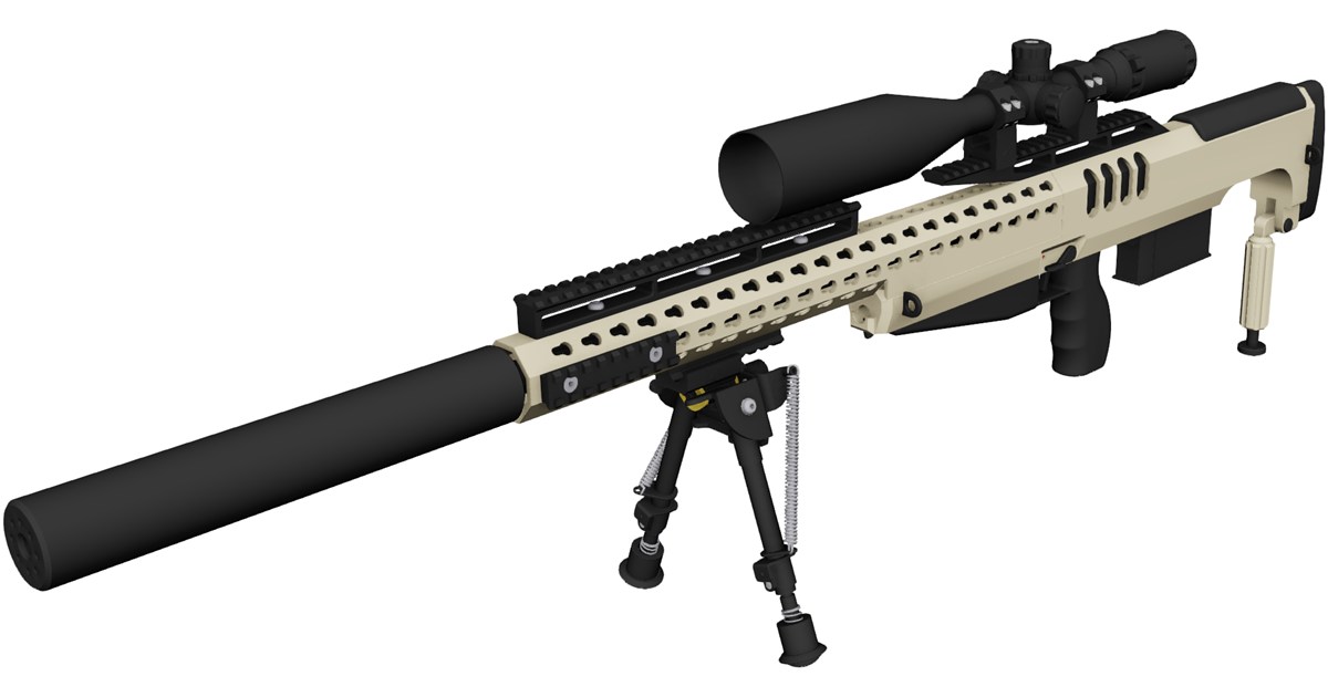
Download a high-precision 3D CAD model of the .338 Lapua Magnum Bullpup SD rifle assembly. Designed for mechanical engineers, product designers, and 3D modeling professionals, this model provides accurate component geometry suitable for digital mockups, ergonomic testing, and rendering.

Key Features & Software Compatibility:

  • Multi-Format Support: Compatible with major CAD software including SolidWorks, AutoCAD, Autodesk Inventor, PTC Creo (Pro/E), Siemens NX, CATIA, and ACIS formats.
  • Detailed Mechanical Layout: Captures the compact, suppressed (SD) bullpup configuration chambered in the powerful .338 Lapua Magnum cartridge.
  • Engineering & Design Ready: Ideal for visual rendering, structural studies, component fitting, and simulation environments.

Continue Reading | ความคิดเห็น

.338 Lapua Magnum Bullpup 3D CAD Model: High-Precision Design Files

Preview Image

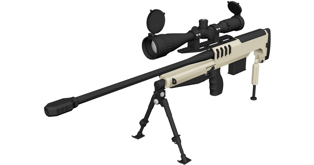
Explore and download a detailed .338 Lapua Magnum Bullpup 3D CAD model tailored for mechanical engineers, product designers, and 3D modeling enthusiasts. This high-precision model captures the ergonomic efficiency of the bullpup configuration combined with the robust specs of the .338 Lapua Magnum platform.

Key Features & Specifications

  • Configuration: Compact bullpup layout featuring integrated receiver, barrel, and stock geometry.
  • High Precision: Modeled with accurate proportions suitable for digital prototyping, spatial analysis, and rendering.
  • Universal Interoperability: Formatted for seamless import into top-tier CAD and BIM workflows.

Supported File Formats & Software

This 3D model is compatible with a wide array of industry-standard computer-aided design software, including:

  • SolidWorks, Autodesk Inventor, AutoCAD
  • PTC Creo / Pro/ENGINEER
  • Siemens NX, CATIA
  • ACIS (.sat) and standard neutral exchange formats

Perfect for engineering study, ergonomic research, and high-quality 3D visualization projects.


Continue Reading | ความคิดเห็น

Unlocking the Power of 3D CAD: How Mechanical Assemblies Come to Life

Wednesday, August 26, 2026

In the fast-paced world of modern engineering and product design, static 2D blueprints are rapidly becoming a thing of the past. Today, complex machinery and intricate mechanical parts rely heavily on sophisticated visualization tools to ensure perfection before physical production ever begins. This is where modern 3D CAD (Computer-Aided Design) technology plays a pivotal role, transforming abstract concepts into fully interactive, functional mechanical assemblies.

Understanding Mechanical Assemblies in Motion

Designing an individual component is only the first step in product development. The true test of engineering lies in how various moving parts interact within a complete mechanism. Through digital assembly, designers can simulate motion, test real-world constraints, and identify potential mechanical interferences early in the design cycle. Seeing a machine come alive through realistic 3D animations not only accelerates the design process but also drastically reduces costly manufacturing errors.

Why Mastering 3D CAD is Essential for Engineers

Whether you are a student, a professional mechanical engineer, or a passionate hobbyist, developing strong proficiency in 3D CAD opens up limitless possibilities. Modern software allows creators to:

  • Build highly precise 3D geometry and parametric models.
  • Perform virtual stress tests and dynamic motion simulations.
  • Streamline collaboration between design, engineering, and manufacturing teams.

With step-by-step practical learning, mastering complex concepts like gear mechanisms, linkage assemblies, and automated machinery becomes significantly easier and more accessible.

Transform Your Creative Workflow Today

Bridging the gap between theoretical engineering and practical application requires hands-on practice and clear, accessible visual guides. By leveraging modern digital tools and high-quality tutorial content, you can easily turn complex mechanical challenges into seamless, practical design solutions. Start exploring realistic mechanical models today and elevate your engineering capabilities to the next level!

3D CAD
Continue Reading | ความคิดเห็น

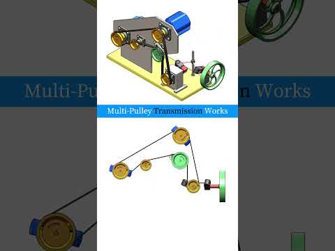
Understanding Multi-Pulley Transmission Systems Through 3D CAD

Tuesday, August 25, 2026

Mechanical power transmission is at the heart of modern machinery, driving everything from household appliances to massive industrial equipment. Among the various methods used to transfer rotational energy, multi-pulley systems stand out for their efficiency, versatility, and mechanical advantage. But how exactly do these intricate systems work under the hood?

The Mechanics Behind Multi-Pulley Systems

A multi-pulley transmission relies on a series of interlinked wheels (pulleys) connected by belts or cables. By altering the relative diameters of these pulleys, mechanical engineers can precisely control speed and torque outputs throughout a machine.

When a smaller drive pulley rotates a larger driven pulley, the output speed decreases while torque increases. Conversely, driving a smaller pulley increases rotational speed at the cost of torque. Combining multiple pulleys allows machines to achieve complex gear ratios, distribute force across multiple axes, and change the direction of rotation seamlessly.

Visualizing Complex Assemblies with 3D CAD

Historically, understanding and designing intricate mechanical assemblies required physical prototypes and manual draft sketches. Today, modern engineers leverage advanced 3D CAD software to model, simulate, and optimize power transmission systems with extreme accuracy.

By breaking down a multi-pulley setup inside a 3D CAD environment, designers can visualize belt tension, analyze stress distribution, and check for spatial clearance issues long before reaching the production floor. This digital precision drastically reduces engineering errors, minimizes material waste, and accelerates the product development cycle.

Practical Applications in Modern Engineering

Multi-pulley transmission systems are ubiquitous across various industries due to their smooth operation and shock-absorption capabilities:

  • Automotive Engines: Serpentine belt systems utilize multiple pulleys to drive the alternator, power steering pump, and air conditioning compressor simultaneously.
  • Industrial Machinery: Manufacturing equipment relies on multi-pulley setups to regulate conveyor belt speeds and drive heavy machinery.
  • Workshop Tools: Drill presses and metal lathes frequently use stepped multi-pulley drives to allow easy speed adjustments depending on the material being worked on.

Conclusion

Whether you are a student, hobbyist, or professional mechanical designer, mastering how power flows through pulley assemblies is fundamental. By utilizing modern 3D CAD tools, complex mechanical concepts become intuitive visual experiences, bridging the gap between theoretical engineering and real-world application.

3D CAD
Continue Reading | ความคิดเห็น

Mastering Mechanical Design: Step-by-Step 3D CAD Assembly & Technical Drawing Guide

Tuesday, August 18, 2026

Mechanical engineering relies heavily on turning complex concepts into tangible, functional components. Whether you are an aspiring engineer, student, or seasoned designer, mastering the full workflow in modern 3D CAD software is essential for bringing your ideas to life with speed and precision.

In this comprehensive breakdown, we explore an end-to-end mechanical design process—from part inspection to complex mechanical assembly and detailed technical drawing generation.

Navigating the Mechanical Assembly Workflow

Building a multi-part mechanical system requires more than just creating individual 3D geometries; it demands a clear understanding of how components interact. During the assembly phase, designers must apply correct mate conditions, mechanical constraints, and alignment checks to ensure smooth kinematic performance.

By utilizing advanced 3D CAD tools, engineers can inspect internal clearances, analyze dynamic motion, and detect component interference long before a physical prototype is manufactured. This digital prototyping phase significantly minimizes material waste and speeds up development cycles.

Translating 3D Models into Precise Technical Drawings

Once your 3D mechanical assembly is finalized, the next crucial step is generating shop-ready manufacturing documentation. A functional digital model relies on standardized 2D blueprints so machinists and technicians can produce parts accurately.

Key aspects of the drawing breakdown include: - Orthographic & Section Views: Generating top, front, and cross-sectional views to reveal internal geometry. - Exploded Views & BOMs: Creating detailed Bill of Materials (BOM) tables and exploded assembly views for seamless assembly lines. - Dimensioning & Tolerancing: Applying essential geometric dimensions and tolerances (GD&T) to guarantee perfect fit and function.

Elevate Your Engineering Workflow

Adopting an integrated, parametric workflow ensures that your design intent remains intact throughout the project lifecycle. When a single parameter changes in a part model, your high-level assembly and 2D blueprints automatically update. Developing proficiency in 3D CAD empowers you to deliver professional, industry-standard engineering deliverables efficiently.

3D CAD
Continue Reading | ความคิดเห็น

Popular Posts Today

 
Support : 3Dcadbrowser | Grabcad | 3Dcontentcentral | D | E | F | G
Copyright © 2028. Engineering 3DCad Appication - All Rights Reserved