
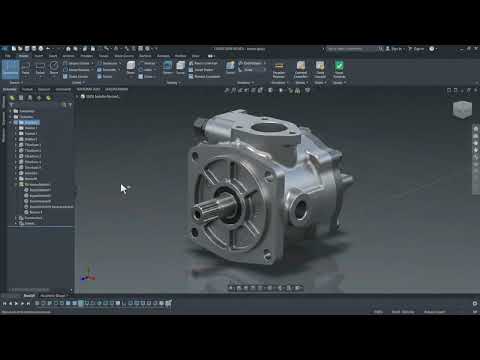
Mechanical engineering relies heavily on turning complex concepts into tangible, functional components. Whether you are an aspiring engineer, student, or seasoned designer, mastering the full workflow in modern 3D CAD software is essential for bringing your ideas to life with speed and precision.
In this comprehensive breakdown, we explore an end-to-end mechanical design process—from part inspection to complex mechanical assembly and detailed technical drawing generation.
Navigating the Mechanical Assembly Workflow
Building a multi-part mechanical system requires more than just creating individual 3D geometries; it demands a clear understanding of how components interact. During the assembly phase, designers must apply correct mate conditions, mechanical constraints, and alignment checks to ensure smooth kinematic performance.
By utilizing advanced 3D CAD tools, engineers can inspect internal clearances, analyze dynamic motion, and detect component interference long before a physical prototype is manufactured. This digital prototyping phase significantly minimizes material waste and speeds up development cycles.
Translating 3D Models into Precise Technical Drawings
Once your 3D mechanical assembly is finalized, the next crucial step is generating shop-ready manufacturing documentation. A functional digital model relies on standardized 2D blueprints so machinists and technicians can produce parts accurately.
Key aspects of the drawing breakdown include: - Orthographic & Section Views: Generating top, front, and cross-sectional views to reveal internal geometry. - Exploded Views & BOMs: Creating detailed Bill of Materials (BOM) tables and exploded assembly views for seamless assembly lines. - Dimensioning & Tolerancing: Applying essential geometric dimensions and tolerances (GD&T) to guarantee perfect fit and function.
Elevate Your Engineering Workflow
Adopting an integrated, parametric workflow ensures that your design intent remains intact throughout the project lifecycle. When a single parameter changes in a part model, your high-level assembly and 2D blueprints automatically update. Developing proficiency in 3D CAD empowers you to deliver professional, industry-standard engineering deliverables efficiently.

