
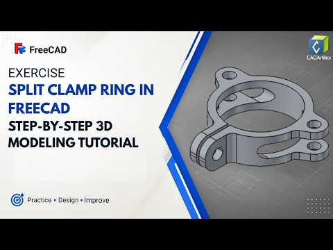
Split clamp rings are fundamental components in mechanical engineering, widely used to secure parts along shafts without causing surface damage. Whether you are building custom robotics, modifying industrial machinery, or 3D printing functional hardware at home, learning how to model this essential part is a valuable skill.
In this step-by-step tutorial, we demonstrate how to design a fully functional Split Clamp Ring using FreeCAD—one of the most powerful open-source 3D CAD software options available today.
Why Learn Split Clamp Ring Design?
Unlike standard solid collar rings that rely on set screws, split clamp rings use clamping force via mechanical fasteners to lock onto a shaft firmly. This design provides superior holding power and prevents wear on the shaft.
Modeling this specific geometry requires a solid grasp of parametric design, geometric constraints, and feature creation, making it an ideal practice project for anyone looking to build confidence in technical design.
Key Steps to Model the Clamp Ring in FreeCAD
- Setting Up the Base Profile: Start in the Part Design Workbench. Create a new body and draw two concentric circles in the Sketcher to define the inner shaft diameter and outer collar dimension.
- Extruding the Main Solid: Pad the sketch to your required height to create the primary cylindrical ring.
- Adding Mounting Lugs & Screw Holes: Create reference planes to model the clamping ears, counterbored screw holes, and threaded receiver holes for your hardware.
- Creating the Split: Use a thin rectangular pocket cut to remove a small section of material through one side of the ring, giving it the flexibility needed to clamp down when tightened.
Best Practices for Parametric Modeling
- Fully Constrain Your Sketches: Always ensure your sketch dimensions and geometric constraints are fully defined. This guarantees stability when modifying your model later.
- Leverage Parametric Flexibility: Design with variables in mind so you can quickly scale the inner diameter for different shaft sizes in future 3D CAD projects.
Conclusion
By mastering these fundamental modeling techniques in FreeCAD, you will gain practical experience that translates directly to real-world mechanical design. Watch the step-by-step video tutorial to follow along, refine your workflow, and take your modern 3D CAD skills to the next level!

