
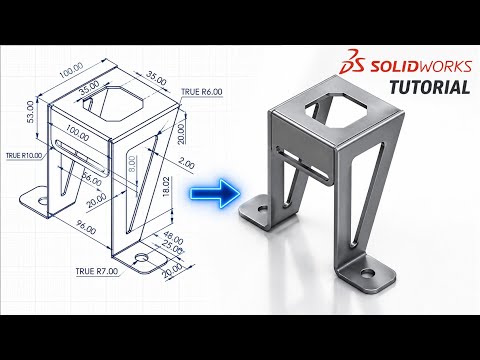
Transitioning from 2D engineering drawings to fully realized 3D models is a crucial skill for modern design engineers, fabricators, and draftspersons. Whether you are upgrading legacy blueprints or streamlining your manufacturing workflow, leveraging modern 3D CAD software like SOLIDWORKS can significantly boost design accuracy and productivity.
In this article, we explore how to seamlessly transform a detailed 2D engineering drawing into an accurate, production-ready 3D sheet metal bracket.
The Advantage of 3D Sheet Metal Design
Why transition from traditional 2D blueprints to 3D modeling? Working directly in a 3D CAD environment allows designers to visualize complex spatial relationships, detect component interferences early, and automatically calculate sheet metal bend allowances.
When manufacturing sheet metal parts like mounting brackets, precision is everything. A single miscalculated bend angle or incorrect flat pattern layout in 2D can result in wasted material and costly shop-floor delays. Translating these designs into 3D guarantees that every flange, hole cutout, and bend line aligns perfectly before reaching production.
Key Steps to Convert a 2D Drawing into a 3D Model
To turn a standard 2D drawing into a parametric 3D sheet metal bracket, follow this simplified workflow inside SOLIDWORKS:
- Analyze the Blueprint: Carefully review all dimensions, material thickness callouts, and inside bend radii specified in the original 2D engineering draft.
- Establish the Base Profile: Recreate or import the foundational view as a fully defined 2D sketch.
- Generate Sheet Metal Features: Use the Base Flange/Tab tool to establish the initial sheet thickness. From there, build the bracket's structure using Edge Flanges and Miter Flanges matching the blueprint specs.
- Detail Cutouts and Hole Patterns: Add mounting holes, slots, or weight-reduction cuts using standard feature cuts across the sheet metal faces.
- Verify the Flat Pattern: Switch to the flattened state to confirm that bend lines, relief cuts, and overall blank dimensions match manufacturing requirements.
Elevate Your Design Capabilities
Mastering the transition from flat 2D drafts to functional 3D models is an invaluable asset for any engineer. By incorporating advanced 3D CAD workflows into your daily operations, you reduce physical prototyping costs, minimize manufacturing errors, and accelerate product development from concept to final assembly.

