
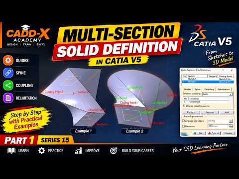
In the world of computer-aided design (CAD), mastering advanced solid modeling techniques is essential for creating complex, organic, and aerodynamic shapes. CATIA V5 remains an industry standard for engineers and designers, offering a vast array of powerful features. Among these, the Multi-Section Solid tool stands out as one of the most versatile functions for creating intricate 3D geometry between multiple profile sections.
Whether you are designing automotive body panels, turbine blades, or consumer products, understanding how to control cross-sectional transitions is crucial for clean, manufacturable models.
Understanding the Multi-Section Solid Tool
The Multi-Section Solid tool allows designers to build a solid body by connecting two or more planar profiles along a designated path. While basic extrusions and pads handle simple prismatic shapes, advanced solid modeling requires precise control over how surfaces blend between distinct cross-sections.
To achieve predictable, smooth geometry without unwanted twists or surface tears, you must master three fundamental elements: Spines, Guides, and Coupling.
Key Components: Spines, Guides, and Coupling
- Spines: The spine acts as the structural backbone of your multi-section feature. It controls the orientation and normal alignment of intermediate sections along the shape's length, ensuring balanced material distribution.
- Guides: Guide curves are user-defined paths that govern the outer boundaries of the solid. They dictate how the edge profile morphs from one section to another, giving you complete engineering control over the outer contour.
- Coupling: Coupling establishes how points on one profile connect to corresponding points on the next profile. Proper coupling prevents surface distortion, self-intersection, and topological errors.
Best Practices for Error-Free Geometry
To achieve consistent success in your solid modeling projects within CATIA V5, keep these practical tips in mind:
- Align Closing Points: Always verify that the closing point vectors on all selected profiles point in the same relative direction. Opposite directions will cause the feature to twist or fail entirely.
- Maintain Vertex Consistency: Whenever possible, create profiles with an equal number of vertices. This simplifies point coupling and ensures cleaner geometry.
- Ensure Smooth Guide Curves: Make sure your guide curves maintain tangency and continuity to prevent sharp breaks or surface errors on the final model.
Conclusion
Mastering the Multi-Section Solid tool is a key milestone for any CAD designer. By understanding how to combine spines, guides, and coupling options effectively, you can tackle complex design challenges and produce professional-grade 3D models with confidence.
