Cad 3D Category

Showing posts with label Solid modeling. Show all posts

Mastering Solid Modeling in CATIA V5: The Ultimate Multi-Section Solid Guide

Friday, September 18, 2026
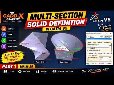
In the world of computer-aided design (CAD), mastering advanced solid modeling techniques is essential for creating complex, organic, and aerodynamic shapes. CATIA V5 remains an industry standard for engineers and designers, offering a vast array of powerful features. Among these, the Multi-Section Solid tool stands out as one of the most versatile functions for creating intricate 3D geometry between multiple profile sections.

Whether you are designing automotive body panels, turbine blades, or consumer products, understanding how to control cross-sectional transitions is crucial for clean, manufacturable models.

Understanding the Multi-Section Solid Tool

The Multi-Section Solid tool allows designers to build a solid body by connecting two or more planar profiles along a designated path. While basic extrusions and pads handle simple prismatic shapes, advanced solid modeling requires precise control over how surfaces blend between distinct cross-sections.

To achieve predictable, smooth geometry without unwanted twists or surface tears, you must master three fundamental elements: Spines, Guides, and Coupling.

Key Components: Spines, Guides, and Coupling

  • Spines: The spine acts as the structural backbone of your multi-section feature. It controls the orientation and normal alignment of intermediate sections along the shape's length, ensuring balanced material distribution.
  • Guides: Guide curves are user-defined paths that govern the outer boundaries of the solid. They dictate how the edge profile morphs from one section to another, giving you complete engineering control over the outer contour.
  • Coupling: Coupling establishes how points on one profile connect to corresponding points on the next profile. Proper coupling prevents surface distortion, self-intersection, and topological errors.

Best Practices for Error-Free Geometry

To achieve consistent success in your solid modeling projects within CATIA V5, keep these practical tips in mind:

  1. Align Closing Points: Always verify that the closing point vectors on all selected profiles point in the same relative direction. Opposite directions will cause the feature to twist or fail entirely.
  2. Maintain Vertex Consistency: Whenever possible, create profiles with an equal number of vertices. This simplifies point coupling and ensures cleaner geometry.
  3. Ensure Smooth Guide Curves: Make sure your guide curves maintain tangency and continuity to prevent sharp breaks or surface errors on the final model.

Conclusion

Mastering the Multi-Section Solid tool is a key milestone for any CAD designer. By understanding how to combine spines, guides, and coupling options effectively, you can tackle complex design challenges and produce professional-grade 3D models with confidence.

Continue Reading | ความคิดเห็น

Mastering Solid Modeling: A Step-by-Step CATIA V5 Tutorial for Beginners

Wednesday, September 16, 2026

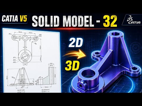
CATIA V5 remains one of the most powerful and widely used software suites in the aerospace and automotive industries. For aspiring engineers and designers, mastering solid modeling is a fundamental step toward professional proficiency. In this latest installment of our tutorial series, we break down Exercise 32, focusing on the seamless transition from a 2D engineering drawing to a fully realized 3D part.

Transitioning from 2D Drawings to 3D Geometry

The core of any mechanical design starts with a blueprint. Understanding how to interpret dimensions, tolerances, and views is crucial before you even touch the software. In this tutorial, we demonstrate how to analyze a 2D technical drawing and plan your sketching strategy. By identifying the primary features of the part first, you can build a more stable and editable model.

The Core Principles of Solid Modeling

In the world of Computer-Aided Design (CAD), solid modeling is about more than just creating shapes; it is about defining the volume, mass, and physical properties of a component. Using CATIA V5’s Sketcher workbench, we start by creating a "constrained" profile. This ensures that your design remains robust—meaning that if you change a single dimension later, the entire model updates correctly without errors.

Once the 2D sketch is finalized, we utilize essential features such as the Pad tool to extrude material and the Pocket tool to remove it. These boolean-like operations are the building blocks of 3D design, allowing you to sculpt your model with surgical precision.

Refining Your Professional Workflow

To move from a beginner to an intermediate level, you must focus on design intent and tree organization. This tutorial covers how to properly name your features and organize your Part Body. We also explore the application of dress-up features like fillets and chamfers, which provide the final engineering touches necessary for a production-ready model.

Whether you are a student or a professional looking to refresh your skills, practicing these exercises is the most effective way to gain confidence in the software. By the end of this guide, you will have a much stronger grasp of solid modeling and be better prepared to tackle complex industrial design challenges.

Continue Reading | ความคิดเห็น

Popular Posts Today

 
Support : 3Dcadbrowser | Grabcad | 3Dcontentcentral | D | E | F | G
Copyright © 2028. Engineering 3DCad Appication - All Rights Reserved