Cad 3D Category

Showing posts with label Reverse Engineering. Show all posts

From Physical Part to CAD: Unlocking the Power of 3D Scanning in Reverse Engineering

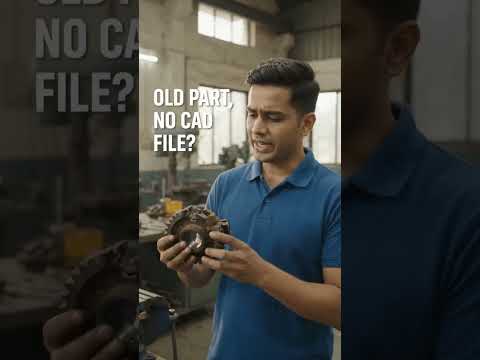
Tuesday, October 27, 2026
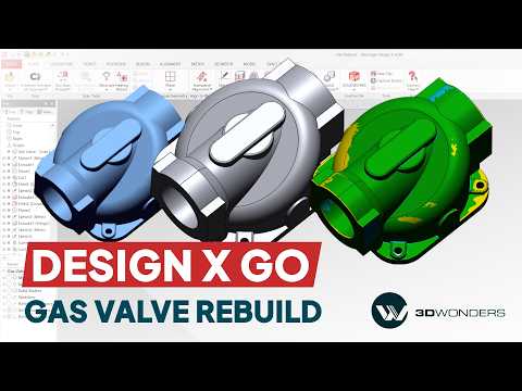
Have you ever wondered how to accurately recreate complex mechanical components when original CAD files are unavailable? Whether you are redesigning legacy hardware or replacing worn-out industrial machinery, reverse engineering provides the ultimate solution. By leveraging modern 3D scanning techniques alongside specialized software, engineers can quickly turn physical objects into fully editable, parametric CAD models.

In this workflow guide, we explore how a complex mechanical gas valve can be accurately reconstructed using Geomagic Design X Go.

Bridging the Gap Between Physical Parts and Digital CAD

Converting raw scan data into usable digital geometry used to be a tedious, manual process. Today, tools like Geomagic Design X Go streamline the entire Scan-to-CAD pipeline. The software accepts dense polygon meshes generated by high-resolution scanners and provides powerful tools to extract feature curves, surfaces, and solid bodies.

When dealing with intricate components such as a gas valve—complete with internal flow channels, precision threads, and mounting flanges—3D scanning captures exact real-world dimensions without destructive testing or manual measurement errors.

Reconstructing the Gas Valve: Key Steps in the Workflow

  1. Data Import and Alignment: The process begins by importing the triangular mesh of the gas valve. The scan is aligned to a logical coordinate system using geometric primitives like planes and cylinders extracted directly from the mesh.
  2. Feature Extraction: Automated region segmentation identifies key functional areas such as valve seats and port openings. Sketch planes are then positioned to extract precise cross-sectional profiles.
  3. Solid Modeling: Using standard parametric modeling operations—such as extrusions, revolves, and sweeps—the full 3D geometry of the gas valve is built step-by-step over the reference mesh.

Why Reverse Engineering Matters for Manufacturing

Integrating robust 3D scanning solutions into your product development workflow significantly reduces prototyping time, eliminates measurement bottlenecks, and enables precise modification of legacy parts. Software like Geomagic Design X Go ensures that your reverse-engineered models maintain a complete parametric feature tree, making future modifications fast and intuitive.

Whether you are restoring critical infrastructure or improving product design, combining digital scan data with powerful CAD reconstruction software is the fastest path from a physical part to a production-ready model.


Continue Reading | ความคิดเห็น

3D Scanning Explained: Bridging the Gap Between Physical Parts and 3D CAD

Tuesday, September 8, 2026

In today's fast-paced engineering landscape, capturing the exact geometry of a physical object is essential for redesign, quality control, and reverse engineering. Whether you need to reproduce a legacy mechanical component without original blueprints or analyze a complex prototype, 3D scanning provides the ultimate solution. This technology seamlessly bridges the gap between the physical world and digital design, transforming tangible parts into workable 3D CAD data.

How 3D Scanning Digitizes Physical Parts

3D scanning works by capturing the surface measurements of a physical object using lasers, structured light, or photogrammetry. As the scanner projects light or laser lines onto the component, advanced sensors calculate millions of spatial data points in seconds.

This process generates a dense "point cloud," which is then connected to form a polygon mesh—a high-fidelity digital representation of the physical object's exterior geometry. From intricate automotive components to custom medical devices, 3D scanners capture complex organic curves and fine details that traditional measuring tools like calipers simply cannot match.

Transforming Raw Scans into Parametric Models

While a raw 3D scan provides an accurate visual surface mesh, it isn't immediately ready for parametric manufacturing or mechanical modification. To unlock its full potential, engineers transfer the mesh data into professional 3D CAD software for reverse engineering.

In this stage, the scanned mesh serves as a precise digital blueprint. Designers use specialized modeling tools within their 3D CAD environment to extract geometric features, align mechanical axes, and rebuild clean, editable solid geometry. This allows engineering teams to modify dimensions, add mounting features, or optimize the design for modern production methods such as 3D printing and CNC machining.

Why Digital Integration Matters for Manufacturing

Connecting physical hardware with digital workflows offers powerful competitive advantages: - Accelerated Product Development: Drastically reduce the time required to measure, model, and iterate existing components. - Legacy Part Preservation: Effortlessly archive and re-manufacture obsolete parts that lack original technical drawings. - Enhanced Quality Inspection: Overlay scanned physical parts against their original digital blueprints to instantly detect manufacturing deviations and tolerances.

By converting physical components into versatile digital assets, modern scanning technology combined with CAD software empowers engineers to innovate faster, improve accuracy, and streamline the entire product lifecycle.

Continue Reading | ความคิดเห็น

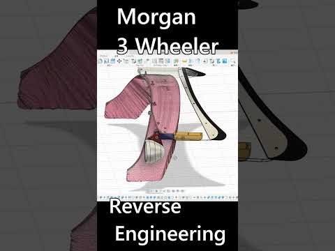
Reverse Engineering Classic Style: Customizing a Morgan 3 Wheeler with 3D CAD

Monday, September 7, 2026

The Morgan 3 Wheeler is an iconic blend of vintage charm and raw motoring enthusiasm. However, when it comes to custom aftermarket modifications, off-the-shelf parts rarely exist. To overcome this challenge, modern automotive builders are turning to digital workflows to design bespoke components—such as a custom folding windscreen—with surgical precision.

From Physical Car to Digital Scan

The reverse engineering process begins by capturing the unique, organic contours of the vehicle. Using high-precision 3D optical scanners, millions of data points are collected to generate a highly accurate point cloud of the car’s front bodywork and cowl section. This non-destructive scanning process ensures every subtle curve and factory mounting point is recorded down to the millimeter, creating a flawless digital foundation.

Refining the Design with 3D CAD

Once the physical geometry is digitized, the scan data is imported into modern 3D CAD software. Working within a parametric digital environment allows engineers to transform raw mesh data into clean, functional solid models.

When designing a complex feature like a custom folding windscreen, 3D CAD provides the ultimate platform to simulate mechanical movement, test hinge clearances, and refine aesthetics. Engineers can evaluate how the glass tilts, verify frame alignment, and make real-time adjustments before committing to physical prototyping or CNC machining. This digital sandbox drastically cuts down on trial-and-error, saving both time and expensive materials.

Bringing Custom Concepts to Life

By combining state-of-the-art scanning tools with advanced 3D CAD design techniques, custom fabrication enters a new era of speed and accuracy. Whether you are building a custom folding windscreen or prototyping intricate engine components, digital reverse engineering eliminates guesswork and delivers a factory-quality finish for custom automotive builds.

Continue Reading | ความคิดเห็น

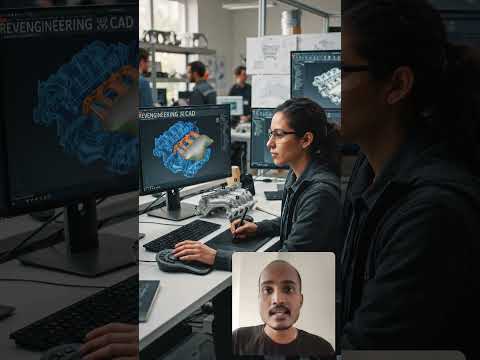
3D Scanning Explained: How to Turn Physical Objects into 3D CAD Models

Sunday, September 6, 2026

Ever wondered how engineers digitize complex, existing mechanical components without starting from scratch? Whether you are dealing with a legacy part that lacks original blueprints or looking to inspect a manufactured piece for quality control, 3D scanning provides the ultimate solution. By bridging the gap between the physical world and digital design environments, this technology has revolutionized modern manufacturing and engineering.

How Does 3D Scanning Work?

3D scanning is the process of analyzing a real-world object or environment to collect precise data on its shape and appearance. Using lasers, structured light, or tactile sensors, the scanner captures millions of measurements from the object's surface.

These measurements form a dense "point cloud," which software connects into a polygonal mesh. From there, specialized reverse-engineering tools process the mesh to create a fully functional, parametric 3D CAD model. This transition allows designers to edit, modify, or analyze the physical part inside their standard design software.

Key Benefits of Digitizing Physical Parts

Converting real components into digital assets opens up endless possibilities for product development:

  • Reverse Engineering: Effortlessly recreate legacy components that no longer have original engineering drawings or design data.
  • Quality Control & Inspection: Compare high-resolution scan data directly against original 3D CAD files to detect manufacturing defects, deformation, or surface wear.
  • Faster Product Iteration: Scan physical hand-made prototypes to rapidly refine and optimize designs digitally before mass production.

Integrating Scan Data into Your Engineering Workflow

Transitioning physical components into a digital format drastically reduces manual measurement errors and accelerates project timelines. Once your scan data is successfully transformed into a clean 3D CAD file, you can easily perform finite element analysis (FEA), optimize geometry for lightweighting, prepare parts for 3D printing, or generate toolpaths for CNC machining.

Final Thoughts

As modern engineering continues toward full digital transformation, 3D scanning stands out as an indispensable bridge between physical reality and digital innovation. By turning real-world components into accurate 3D models, teams save time, enhance accuracy, and streamline their entire product lifecycle.

Continue Reading | ความคิดเห็น

Mastering Surface Reverse Engineering in 3D CAD: A Complete Guide

Tuesday, August 25, 2026

In today’s fast-paced product development landscape, bringing physical objects into the digital realm is more essential than ever. Surface reverse engineering bridges this gap by allowing engineers and designers to convert physical components into accurate digital models using advanced 3D CAD technology.

Whether you are working with legacy mechanical parts or intricate organic shapes, understanding how surface reverse engineering works can dramatically streamline your design workflow.

What is Surface Reverse Engineering?

Surface reverse engineering is the process of capturing a physical object’s exact geometry using 3D scanners, then reconstructing those surfaces into a parametric digital model. Unlike basic solid modeling, surface modeling focuses on complex curves, freeform shapes, and aesthetic surfaces that cannot easily be recreated using standard geometric primitives.

By acquiring point cloud or mesh data from a scan, engineers create clean, mathematically precise non-uniform rational B-splines (NURBS) surfaces over the scanned mesh, recreating the physical product with high dimensional accuracy.

Why Is It Essential for Mechanical Design?

Reverse engineering plays a pivotal role across various industries, including automotive, aerospace, industrial design, and consumer electronics. Here is why it is so valuable:

  • Legacy Part Recreation: Fabricate replacement parts for older machinery where original blueprints or digital files no longer exist.
  • Competitive Analysis: Analyze existing market products to improve performance, ergonomics, or manufacturability.
  • Rapid Prototyping: Transition seamlessly between physical clay prototypes and digital designs in modern 3D CAD software environments.
  • Quality Inspection: Compare manufactured physical parts against original design specifications to ensure tight tolerances.

Key Steps in the Reverse Engineering Process

  1. Data Acquisition: High-resolution 3D scanning generates a detailed point cloud or polygon mesh of the physical part.
  2. Mesh Optimization: Clean up noise, fill gaps, and smooth out irregularities in the scanned mesh.
  3. Surface Fitting: Extract key features and build smooth patches over the mesh to capture complex surface contours.
  4. Parametric Integration: Import the reconstructed surfaces into your 3D CAD program (such as SolidWorks) to build fully functional solid models ready for production.

Final Thoughts

Mastering surface reverse engineering unlocks endless possibilities for mechanical design and product innovation. By leveraging high-precision scanning alongside robust modeling tools, engineers can turn physical concepts into digital reality faster and more efficiently than ever before.

3D CAD
Continue Reading | ความคิดเห็น

Popular Posts Today

 
Support : 3Dcadbrowser | Grabcad | 3Dcontentcentral | D | E | F | G
Copyright © 2028. Engineering 3DCad Appication - All Rights Reserved