Cad 3D Category

Showing posts with label Structural Design. Show all posts

Beneath the Surface: How 3D Engineering Reveals the Secrets of Bridge Foundations

Thursday, October 8, 2026

Have you ever stood atop a massive bridge and wondered how it effortlessly supports thousands of tons of traffic while resisting raging river currents? While soaring arches and steel cables capture our imagination, the true marvel of bridge design lies hidden deep underwater and underground.

Understanding how these giant structures stay upright against unrelenting natural forces requires looking beneath the surface—where modern structural analysis plays a crucial role.

The Hidden Challenge Beneath the Waves

Bridge foundations face an extraordinary combination of dynamic loads. In addition to carrying the static weight of the bridge itself and the constant impact of moving vehicles, underwater foundations must endure intense hydrostatic pressure, shifting soil, and scour—the erosion of riverbed sediment around support piers.

To ensure safety, civil engineers design deep foundation systems such as driven piles, drilled shafts, and submerged caissons. These structures transfer heavy loads down through weak upper soil layers directly into solid bedrock.

Simulating Complex Forces with 3D Engineering

In traditional civil design, engineers relied heavily on two-dimensional blueprints and manual structural calculations. Today, advanced 3D engineering software revolutionizes how foundation systems are evaluated. Through three-dimensional modeling and Finite Element Analysis (FEA), engineers can visualize stress distributions, fluid dynamics, and soil-structure interactions in real time.

By integrating 3D engineering tools into the design phase, engineering teams can simulate extreme scenario loads—such as severe flooding or seismic events—long before construction begins. This allows for precise optimization of foundation depth, material thickness, and structural reinforcement, drastically reducing safety risks and project costs.

Building Safer Infrastructure for Tomorrow

As infrastructure demands grow and environmental conditions become increasingly unpredictable, accurate structural modeling is essential. Leveraging state-of-the-art 3D engineering empowers engineers to build resilient, long-lasting bridges capable of standing strong for generations.

The next time you cross a massive bridge, remember that the most impressive feat of engineering is the invisible foundation holding it all together.


Continue Reading | ความคิดเห็น

One-Way vs. Two-Way Slabs Explained: A Guide to Visualization with Civil 3D

Wednesday, September 30, 2026

Concrete slabs are fundamental structural components in civil engineering, forming the floors, roofs, and decks of modern buildings. When planning and visualizing these elements in advanced drafting workflows like Civil 3D, understanding the key differences between one-way and two-way slabs is essential for structural integrity, accurate load estimation, and cost efficiency.

Here is a clear breakdown of how one-way and two-way slabs work, how they differ, and why their design matters.

What is a One-Way Slab?

A one-way slab is a structural element supported primarily on two opposite sides by parallel beams or walls. Because of this support configuration, structural loads are transferred along a single direction.

  • Span Ratio: A slab is categorized as one-way when the ratio of the longer span ($L_y$) to the shorter span ($L_x$) is equal to or greater than 2 ($L_y / L_x \ge 2$).
  • Bending Behavior: The slab bends primarily along its shorter span, forming a cylindrical shape under load.
  • Reinforcement: Main reinforcement steel bars are placed along the shorter direction to resist bending moments, while secondary (distribution) steel is placed along the longer span to withstand temperature changes and shrinkage.

What is a Two-Way Slab?

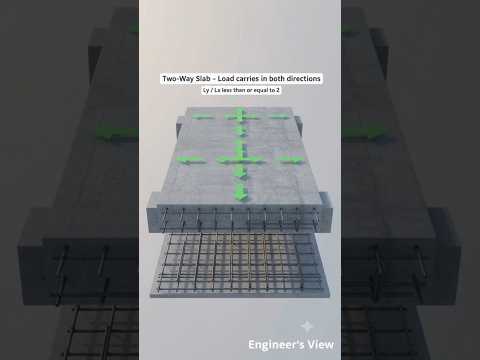
A two-way slab is supported along all four edges by beams or structural walls. As a result, the loads applied to the slab surface are distributed in both orthogonal directions.

  • Span Ratio: A slab acts as a two-way slab when the ratio of the longer span ($L_y$) to the shorter span ($L_x$) is less than 2 ($L_y / L_x < 2$).
  • Bending Behavior: The slab bends in both directions, forming a dish-like or spherical shape under load.
  • Reinforcement: Main reinforcement steel is provided in both directions to accommodate bending moments occurring along both axes.

Key Differences at a Glance

  1. Load Distribution: One-way slabs transfer loads to two supporting beams, whereas two-way slabs distribute loads across four surrounding supports.
  2. Thickness & Material Savings: Two-way slabs are generally thinner and require less concrete volume for the same load capacity due to efficient multidirectional load transfer.
  3. Application: One-way slabs are ideal for long, narrow rectangular spaces (like hallways and verandas), while two-way slabs are commonly used for square or nearly square rooms.

Bridging Structural Analysis and 3D Modeling

Incorporating accurate structural geometries into broader infrastructure and land development project models using Civil 3D allows engineers and site planners to better visualize spatial arrangements, manage elevations, and ensure seamless coordination between civil and structural design teams.

Whether designing small residential platforms or large commercial floor systems, mastering the fundamentals of slab behavior ensures safer, more cost-effective engineering decisions from initial concept to final construction.

Continue Reading | ความคิดเห็น

Popular Posts Today

 
Support : 3Dcadbrowser | Grabcad | 3Dcontentcentral | D | E | F | G
Copyright © 2028. Engineering 3DCad Appication - All Rights Reserved