Cad 3D Category

Showing posts with label Revit 3D. Show all posts

Step-by-Step Guide: How to Create a Custom Ceiling Dome Camera in Revit 3D

Thursday, October 22, 2026
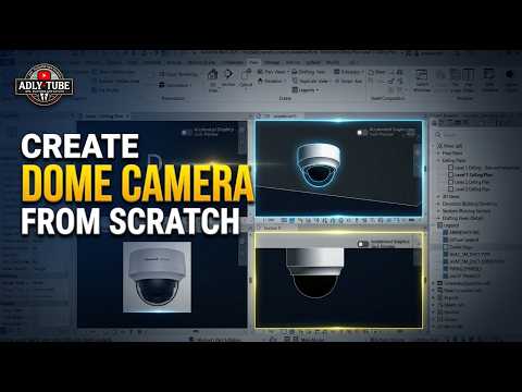
Designing security systems in Building Information Modeling (BIM) requires accurate and detailed components. While default software libraries offer standard elements, learning how to build custom parametric families gives you full control over your project aesthetics and data integrity. In this guide, we will walk you through the step-by-step process of creating a custom ceiling-mounted dome CCTV camera using Revit 3D.

Step 1: Setting Up the Ceiling-Based Family Template

To begin, open Autodesk Revit and create a new family project. Since this security camera attaches directly to a ceiling, select the Metric Electrical Fixture ceiling based or Generic Model ceiling based template. Once loaded, set up your reference planes for height, width, and radius. Establishing a robust reference framework early ensures your camera geometry resizes correctly when adding parametric controls.

Step 2: Modeling the Base and Glass Dome

With your skeleton framework in place, switch to elevation and 3D views to start modeling the camera components: - The Camera Base: Use the Extrusion or Revolve tool to create the cylindrical mounting base that attaches flush to the ceiling surface. - The Camera Dome: Select the Revolve command to sketch half of the spherical lens shield. Draw an axis line and revolve the profile 360 degrees. Assign a glass or transparent plastic material to this geometry so it renders realistically.

Utilizing these core modeling tools allows you to craft high-precision components within Revit 3D, keeping your file sizes lightweight while maintaining visual fidelity.

Step 3: Assigning Materials and Data Connectors

A functional BIM model goes beyond visual geometry—it must contain intelligent project data. - Material Parameters: Assign instance or type parameters to the base and dome materials. This allows team members to easily swap colors or surface finishes in the main project environment. - Electrical/Data Connectors: Add a Security or Electrical Data Connector to the top of the mounting base. Configure the system classification so engineers can connect the camera to security panels and power circuits.

Conclusion

Creating custom families like a ceiling-mounted dome camera boosts both the accuracy and professional presentation of your BIM models. By mastering these parametric modeling techniques, you can tailor any security fixture to your exact project specifications and elevate your overall workflow in Revit 3D. Start building your custom family library today!

Continue Reading | ความคิดเห็น

Master Revit 3D: A Beginner’s Guide to Views, Templates, and Units

Monday, September 28, 2026

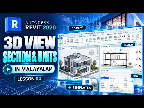
Autodesk Revit is one of the most powerful Building Information Modeling (BIM) software tools used by architects, engineers, and designers worldwide. Whether you are just starting your BIM journey or looking to refine your digital modeling workflow, understanding fundamental project controls is essential. In this guide, we will cover the core steps to set up project templates, configure units, and create detailed views to build stunning Revit 3D models efficiently.

Setting Up Project Templates and Units

Before diving into geometry and wall placements, establishing correct project settings is crucial. Starting with the right project template ensures you have access to pre-configured families, line weights, and view settings tailored to your specific discipline.

Once your template is loaded, setting your project units is the immediate next step. Whether working in millimeters, meters, or feet and inches, configuring units at the beginning prevents costly scaling mistakes later in the design process.

Navigating and Mastering Revit 3D Views

Visualizing your design in a three-dimensional space brings project concepts to life. When working in Revit 3D, spatial awareness is everything. Revit allows users to dynamically rotate, pan, and zoom around building components, giving you total control over design visibility.

Creating dedicated 3D views enables designers to focus on specific building elements, perform shadow studies, or prepare isometric views for presentations. You can easily adjust display styles—from wireframe to realistic rendering—to evaluate how materials and geometry interact in real-world conditions.

Utilizing Section Views for Technical Accuracy

While 3D views give an overall perspective, section views reveal the internal logic of a structure. By cutting a section plane through your floor plan, you gain immediate access to vertical alignment, slab thicknesses, ceiling heights, and structural connections. Section views automatically update in real-time alongside any plan modifications, ensuring your project documentation remains fully synchronized.

Conclusion

Mastering these foundational concepts—templates, project units, 3D navigation, and section detailing—is key to seamless architectural drafting. Implementing these techniques will significantly elevate your BIM workflow and empower you to create precise Revit 3D designs with confidence. Start applying these tools today to build cleaner, more accurate digital models!

Continue Reading | ความคิดเห็น

Popular Posts Today

 
Support : 3Dcadbrowser | Grabcad | 3Dcontentcentral | D | E | F | G
Copyright © 2028. Engineering 3DCad Appication - All Rights Reserved