

Saturday, October 10, 2026
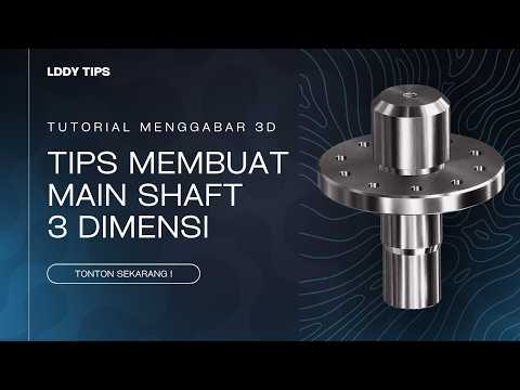
Mechanical design often requires creating complex cylindrical components that transmit power efficiently. One of the most fundamental parts in power transmission systems is the main shaft, frequently customized with inner and outer splines to ensure seamless torque transfer. Whether you are a mechanical engineering student or a seasoned professional, mastering Autodesk 3D software is crucial for creating accurate and manufacturable shaft models.
Understanding Inner and Outer Splines
Splines are ridges or teeth on a drive shaft that mesh with matching grooves in a mating piece to transfer rotational motion and torque.
- Outer Splines: Located on the external surface of the shaft, these teeth fit into the internal spline of a gear, hub, or coupling.
- Inner Splines: Machined inside a hollow section or bore of the shaft, these allow secondary shafts or splined components to insert directly inside.
Designing both features on a single main shaft requires a structured workflow to maintain proper dimensions, strength, and tolerances.
Key Steps to Modeling a Splined Shaft
- Establish the Base Shaft Geometry: Start by creating the primary shaft body using basic revolve or extrude features. Ensure all primary reference planes are set correctly.
- Model the Outer Spline: Sketch the precise tooth profile on the outer diameter. Use circular pattern features to replicate the tooth profile uniformly around the central axis.
- Create the Inner Spline: Define a centered bore along the longitudinal axis. Sketch the internal spline profile and apply a cut-extrude command to form the inner teeth.
- Apply Stress Relief Features: Add fillets and chamfers at key transitions to minimize stress concentrations and prepare the design for manufacturing.
Creating splines efficiently requires a clean geometry setup in your Autodesk 3D workspace so that parameters can be easily updated later if design specifications change.
Essential Tips for Precise Mechanical Design
To ensure your 3D model is accurate and ready for simulation or production: * Use Parametric Constraints: Fully constrain your sketches using exact dimensions, pitch diameters, and tooth counts rather than visually estimating shapes. * Leverage Standard Libraries: Utilize built-in design accelerators whenever possible to generate standardized spline profiles according to ISO or ANSI standards.
With consistent practice, you can elevate your mechanical modeling expertise and streamline your engineering workflow using Autodesk 3D tools. Start building your main shaft model today to master these key techniques!


