Cad 3D Category

Showing posts with label Autodesk Revit. Show all posts

How to Create Bridge Pillars and Abutments Using 3D BIM in Autodesk Revit

Monday, October 26, 2026
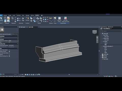
Modern civil engineering relies heavily on digital workflows to ensure precision, structural integrity, and efficient project delivery. When designing complex transportation infrastructure like highways and bridges, utilizing 3D BIM (Building Information Modeling) methodologies has become the industry standard. In bridge engineering, modeling critical substructure elements—such as piers, pillars, and abutments—demands accurate geometry and seamless structural coordination.

Why Use Autodesk Revit for Bridge Substructures?

Piers and abutments serve as the backbone of bridge structures, bearing heavy loads and transferring them safely to the foundation. Traditional 2D CAD drafting often falls short in visualizing complex geometric intersections and reinforcement details. By implementing 3D BIM workflows inside Autodesk Revit, structural engineers and students alike can construct dynamic, parametric digital models that automatically update across all plans, elevations, and section views.

Key advantages include: - Clash Detection: Spot structural spatial conflicts early in the design phase. - Parametric Flexibility: Easily adjust pier heights, footing sizes, and abutment dimensions. - Accurate Quantity Takeoffs: Generate precise concrete and structural schedules automatically.

Key Steps to Modeling Piers and Abutments

  1. Establish Levels and Grids: Begin by setting up project datum elements, including reference elevations for foundation footings, pier caps, and bridge deck levels.
  2. Model Abutments with Precision: Use parametric wall or structural foundation families to build the end-support abutments, ensuring proper wingwall alignment and bearing seat placement.
  3. Construct Support Pillars: Place middle piers and columns, tailoring their geometry—whether cylindrical, rectangular, or tapered—to withstand environmental and structural load demands.
  4. Integrate Reinforcement and Annotations: Apply structural rebar detailing inside the 3D model to create comprehensive construction documentation.

Final Thoughts

Whether you are a student showcasing an academic bridge construction project or a professional structural designer, mastering 3D BIM with Autodesk Revit significantly elevates the quality and accuracy of your work. Embracing these advanced digital workflows ultimately bridges the gap between conceptual design and real-world construction success.

Continue Reading | ความคิดเห็น

Master Revit 3D: A Beginner’s Guide to Views, Templates, and Units

Monday, September 28, 2026

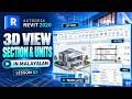
Autodesk Revit is one of the most powerful Building Information Modeling (BIM) software tools used by architects, engineers, and designers worldwide. Whether you are just starting your BIM journey or looking to refine your digital modeling workflow, understanding fundamental project controls is essential. In this guide, we will cover the core steps to set up project templates, configure units, and create detailed views to build stunning Revit 3D models efficiently.

Setting Up Project Templates and Units

Before diving into geometry and wall placements, establishing correct project settings is crucial. Starting with the right project template ensures you have access to pre-configured families, line weights, and view settings tailored to your specific discipline.

Once your template is loaded, setting your project units is the immediate next step. Whether working in millimeters, meters, or feet and inches, configuring units at the beginning prevents costly scaling mistakes later in the design process.

Navigating and Mastering Revit 3D Views

Visualizing your design in a three-dimensional space brings project concepts to life. When working in Revit 3D, spatial awareness is everything. Revit allows users to dynamically rotate, pan, and zoom around building components, giving you total control over design visibility.

Creating dedicated 3D views enables designers to focus on specific building elements, perform shadow studies, or prepare isometric views for presentations. You can easily adjust display styles—from wireframe to realistic rendering—to evaluate how materials and geometry interact in real-world conditions.

Utilizing Section Views for Technical Accuracy

While 3D views give an overall perspective, section views reveal the internal logic of a structure. By cutting a section plane through your floor plan, you gain immediate access to vertical alignment, slab thicknesses, ceiling heights, and structural connections. Section views automatically update in real-time alongside any plan modifications, ensuring your project documentation remains fully synchronized.

Conclusion

Mastering these foundational concepts—templates, project units, 3D navigation, and section detailing—is key to seamless architectural drafting. Implementing these techniques will significantly elevate your BIM workflow and empower you to create precise Revit 3D designs with confidence. Start applying these tools today to build cleaner, more accurate digital models!

Continue Reading | ความคิดเห็น

Popular Posts Today

 
Support : 3Dcadbrowser | Grabcad | 3Dcontentcentral | D | E | F | G
Copyright © 2028. Engineering 3DCad Appication - All Rights Reserved