Cad 3D Category

Showing posts with label Engineering CAD. Show all posts

Streamline Your Engineering CAD Workflows: Eliminate Revision Drift and Project Delays

Saturday, October 31, 2026
In today’s fast-paced technical landscape, managing complex engineering projects requires precision, speed, and seamless team collaboration. However, many organizations still struggle with the friction caused by inefficient document control systems. From lost drawings to chaotic file versions, mismanaged engineering CAD data frequently leads to project bottlenecks, costly rework, and missed deadlines.

The Hidden Cost of Fragmented Reviews and Revision Drift

One of the biggest hurdles technical teams face is revision drift. When multiple engineers, project managers, and external contractors collaborate across disparate channels, keeping track of the latest design iteration becomes a major operational headache. Fragmented team reviews conducted via scattered email threads and disjointed markup tools only aggravate the issue.

Without a centralized control hub, critical updates get overlooked, and team members end up working on outdated files. To keep projects moving forward smoothly, modern firms need a robust platform tailored specifically for engineering CAD management and document control.

Smarter Engineering Document Control with WiseINDEX

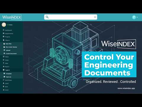
WiseINDEX directly addresses these pain points by providing a streamlined, intelligent approach to document control. Instead of losing valuable time searching for correct files or untangling conflicting feedback, WiseINDEX centralizes your project assets into an intuitive, secure ecosystem.

Key benefits of optimizing your workflow with WiseINDEX include:

  • A Single Source of Truth: Eliminate version confusion by ensuring every stakeholder accesses the correct, up-to-date drawings and specifications at all times.
  • Unified Team Collaboration: Consolidate reviews into a shared, transparent environment, replacing fragmented email chains with actionable design feedback.
  • Controlled Revision History: Automatically track every modification to prevent costly errors during fabrication or construction.

Accelerate Your Project Timelines

Managing your engineering CAD environment shouldn't slow your team down. By adopting specialized document management tools like WiseINDEX, you can eliminate structural inefficiencies, minimize project risks, and significantly boost your team’s productivity.

Ready to see how it works? Watch our complete walkthrough to discover how WiseINDEX transforms complex document management into an effortless, reliable workflow.


Continue Reading | ความคิดเห็น

Mastering Engineering CAD: The Ultimate Guide from Digital Blueprint to Physical Reality

Saturday, October 10, 2026

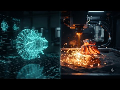
In today's fast-paced industrial landscape, the journey from a spark of an idea to a tangible product is a feat of modern technological synergy. This seamless transition is powered by the evolution of digital manufacturing tools that have redefined how we conceive and create. At the heart of this revolution lies Engineering CAD, the sophisticated software that allows designers to build, test, and refine blueprints in a virtual environment before a single atom of material is moved.

The Digital Blueprint: Where Innovation Begins

The process begins with Computer-Aided Design. Gone are the days of manual drafting tables; modern Engineering CAD provides a high-fidelity, multi-dimensional workspace where every measurement is precise and every mechanical constraint is calculated. This digital blueprint serves as more than just a visual guide—it is a comprehensive data set that defines the geometry, material properties, and functional limits of a component. By utilizing these advanced tools, engineers can simulate real-world stresses and thermal dynamics, ensuring the final product is optimized for peak performance.

Bridging the Gap: The Role of CAM

Once the digital model is perfected, the next critical step is Computer-Aided Manufacturing (CAM). CAM acts as the essential bridge between the virtual world and the factory floor. It takes the complex data from your Engineering CAD file and translates it into G-code—the specialized language that tells CNC machines or 3D printers exactly how to move, cut, or extrude. This automated workflow minimizes human error and significantly accelerates the production cycle, enabling rapid prototyping and the creation of complex geometries that were once deemed impossible.

Physical Reality: The Power of 3D Printing

The final stage of the journey is the physical realization of the object. While subtractive manufacturing remains vital, additive manufacturing (3D printing) has revolutionized the industry by allowing for unprecedented design freedom. Whether you are creating a custom medical implant or a lightweight aerospace bracket, the transition from software to hardware is now faster than ever. By mastering the integrated workflow of CAD, CAM, and 3D printing, creators can push the boundaries of innovation, turning visionary digital concepts into high-quality physical realities.

Continue Reading | ความคิดเห็น

Master the Textmask Command: Essential Engineering CAD Tips for Cleaner Drawings

Sunday, September 27, 2026

When working on complex technical drawings, clarity is the most important factor. There is nothing more frustrating than trying to read critical dimensions or annotations that are obscured by hatch patterns, grid lines, or overlapping geometry. In the professional world of Engineering CAD, maintaining a clean and readable workspace is a hallmark of a high-quality project.

One of the most effective yet underutilized tools to solve this problem is the TEXTMASK command. In this guide, we will explore how this feature can transform your workflow and improve the professional quality of your documentation.

What is Textmask in AutoCAD?

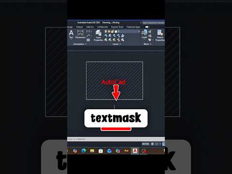
The Textmask command creates a "mask" or a hidden background behind your text or MText objects. This mask automatically hides any drawing elements (lines, circles, or hatches) that sit directly behind the text. Unlike simply moving text to an empty space, Textmask allows you to place annotations exactly where they need to be—even over busy areas—without sacrificing legibility.

How to Use the Textmask Command

Using this tool is straightforward and can be done in just a few seconds. Follow these steps: 1. Type the Command: Type TEXTMASK into the command line and press Enter. 2. Select the Text: Click on the text or multiline text (MText) objects you wish to mask. 3. Adjust Settings (Optional): You can enter 'O' for Options to choose the mask type (Wipeout, Solid, or 3D Face) and adjust the offset distance. 4. Apply: Press Enter again to complete the process.

Your text will now appear clearly with a clean buffer around it, ensuring that your Engineering CAD designs remain professional and easy to interpret for contractors and manufacturers.

Why Every CAD Drafter Should Use It

In a busy project, you often don't have the luxury of "dead space" to place your notes. Using Textmask ensures that your annotations stand out. Furthermore, if you need to revert the changes, the TEXTUNMASK command allows you to remove the background instantly without damaging the underlying geometry.

Mastering these small but powerful tips is what separates a beginner from a professional in the field of Engineering CAD. By implementing the Textmask command into your daily routine, you save time on manual trimming and ensure your final outputs are always top-tier.

Continue Reading | ความคิดเห็น

Popular Posts Today

 
Support : 3Dcadbrowser | Grabcad | 3Dcontentcentral | D | E | F | G
Copyright © 2028. Engineering 3DCad Appication - All Rights Reserved