Cad 3D Category

Showing posts with label Engineering Drawing. Show all posts

Cracking the Code: How to Ace Engineering Drawing Questions in Civil Engineering Interviews

Friday, November 13, 2026
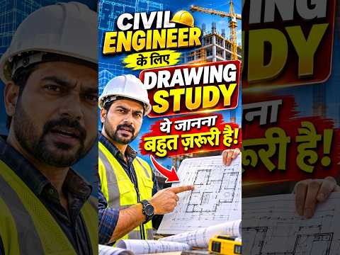
Landing your dream job as a civil engineer requires more than just theoretical knowledge; it demands practical, site-ready skills. During technical job interviews, interviewers often present candidates with structural plans to test their real-world expertise. If you want to stand out from the competition, mastering Engineering Drawing is one of the most critical steps you can take.

Many aspiring engineers stumble when asked to interpret blueprints on the spot. Here is a breakdown of why interviewers ask these questions, common pitfalls to avoid, and how you can prepare to ace your next technical round.

Why Interviewers Focus on Drawing Interpretation

In civil engineering, blueprints are the primary language of construction. Whether you are supervising a site, calculating material quantities, or coordinating with architects, your ability to interpret plans determines project success.

When recruiters present an Engineering Drawing during an interview, they are not just checking if you recognize basic shapes. They want to evaluate your attention to detail, spatial awareness, and your ability to spot critical site notes, scale variations, and structural specifications under pressure.

Common Interview Traps to Watch Out For

Interviewers often include tricky elements in drawing assessments to see if you are paying close attention. Some of the most common challenges include:

  • Overlooking General Notes: Candidates often jump straight to the plan view while ignoring crucial title block details, concrete grades, or rebar specifications.
  • Unit and Scale Errors: Confusing structural scale ratios or mixing up metric and imperial dimensions.
  • Sectional View Confusion: Struggling to project 2D cross-sections into 3D structural elements like beams, columns, and footings.

How to Prepare and Build Confidence

To ensure you are never caught off guard during an interview, follow these practical preparation steps:

  1. Practice with Real Site Plans: Move beyond basic textbook diagrams. Obtain real-world structural and architectural blueprints to practice reading legends, gridlines, and elevation views.
  2. Memorize Standard Symbols: Revisit standard symbols, line types, and hatch patterns used for different building materials.
  3. Double-Check Legends First: Make it a habit to examine the title block, revision history, and notes before answering any question about a plan.

With dedicated practice, you can confidently analyze any Engineering Drawing put in front of you and turn a potentially tricky interview question into your greatest strength.


Continue Reading | ความคิดเห็น

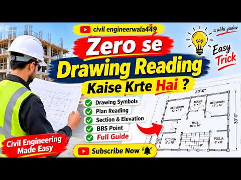
How to Read an Engineering Drawing: A Complete Beginner's Guide

Saturday, October 31, 2026

Stepping onto a construction site or opening a blueprint file for the first time can feel overwhelming. For students, fresh graduates, and site workers, mastering the skill of reading an engineering drawing from scratch is essential for career success. These technical drawings serve as the universal language of construction and design, translating complex architectural concepts into clear instructions for real-world execution.

Key Components Every Beginner Should Know

Before diving into complex site plans, it is important to understand the fundamental elements that make up a standard structural layout:

  • Title Block: Located at the bottom right corner, this section contains critical project metadata, including project name, drawing scale, author, date, and revision history.
  • Legend and Symbols: Drawings use standardized graphical symbols to represent materials, electrical points, plumbing lines, and structural members. Always refer to the legend to avoid misinterpretation.
  • Grid Lines and Dimensions: Numerical and alphabetical grid lines provide precise reference points across the site, allowing engineers to locate columns, walls, and foundations accurately.

A Step-by-Step Guide to Reading Blueprints

Interpreting a civil engineering drawing effectively requires a structured, step-by-step approach rather than trying to process the entire layout at once:

  1. Review the Title Block and General Notes: Always read the general notes first. They outline structural codes, material specifications, soil bearing capacities, and critical site instructions.
  2. Examine the Floor Plan View: The top-down plan view gives an overall understanding of spatial arrangements, room dimensions, wall thicknesses, and structural grid alignments.
  3. Analyze Elevations and Cross-Sections: While plan views show horizontal layouts, elevation drawings reveal vertical dimensions, floor heights, and structural levels. Cross-sections provide a deep look inside walls and foundations.
  4. Cross-Reference Detail Callouts: Small detail drawings explain complex structural connections, steel rebar arrangements, and material joining techniques.

Conclusion

Reading technical drawings with accuracy is a core competency that develops with practice. By breaking down drawings into digestible sections—starting with title blocks and moving through plans, elevations, and details—you can confidently navigate any construction blueprint on site.

Continue Reading | ความคิดเห็น

Essential Tools Every Student Needs for Engineering Drawing

Saturday, October 10, 2026

Whether you are an engineering student or a beginner in technical design, having the right equipment is essential for producing accurate, clean, and professional drafts. While computer-aided design (CAD) software dominates modern industry, mastering traditional manual engineering drawing remains a crucial foundational skill. It sharpens your spatial awareness, attention to detail, and overall understanding of geometric principles.

To help you get started, here is a guide to the most essential tools required for technical drafting.

1. Drawing Boards and T-Squares

A sturdy drawing board provides a smooth, rigid surface essential for keeping paper flat and stable. Paired with a standard T-square, it allows you to draw consistent horizontal lines easily while serving as a reliable guide for your other drafting tools.

2. Set Squares and Protractors

Set squares (typically 30-60 degree and 45-45 degree triangles) are essential for creating vertical and precise angled lines. When combined with a quality protractor, these tools ensure that every angle in your engineering drawing adheres strictly to exact specifications.

3. Precision Compasses and Dividers

Drawing clean circles and smooth arcs requires a high-grade drafting compass. A divider works alongside it to transfer measurements from your scale ruler directly onto your drawing paper without altering proportions.

4. Technical Pencils and Erasers

Graded graphite pencils are fundamental in technical sketching. Harder leads (such as 2H or 4H) create faint construction lines, while softer leads (like HB or B) are used to define final visible outlines. Using a quality vinyl eraser along with an erasing shield keeps your sheet clean and prevents smudging during corrections.

Conclusion

Equipping yourself with reliable drafting instruments makes a significant difference in the quality and precision of your technical work. By practicing regularly with these foundational tools, you will build a strong drafting discipline, taking your engineering drawing skills to a professional level.

Continue Reading | ความคิดเห็น

Mastering AutoCAD: How to Convert a 2D Engineering Drawing into a 3D Model

Sunday, September 27, 2026

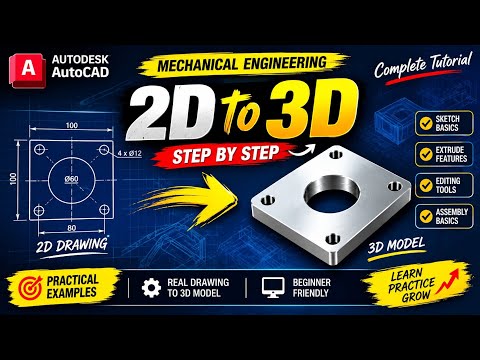
In the world of mechanical design and manufacturing, transforming a flat concept into a realistic spatial visualization is a fundamental skill. AutoCAD remains one of the premier software tools for turning a preliminary engineering drawing into a functional 3D object. Whether you are a mechanical engineering student or an aspiring CAD technician, learning how to seamlessly bridge the gap between 2D drafting and 3D modeling will dramatically enhance your workflow and design capabilities.

Step 1: Preparing Your 2D Layout in AutoCAD

Every successful 3D model begins with an accurate 2D foundation. Before jumping into extrusions and solid modeling, you must establish precise geometry on your drawing plane:

  • Establish Base Geometry: Draw the main profile of your component (such as an Auto Guide) using precise dimensions and coordinates.
  • Clean Up Boundaries: Trim unnecessary overlapping lines, close any open loops, and convert individual line segments into unified poly-lines using the JOIN command or create a single REGION.
  • Verify Precision: A clean and mathematically precise 2D engineering drawing prevents geometry errors during the 3D conversion process, ensuring seamless extrusions later on.

Step 2: Transitioning to the 3D Modeling Environment

Once your 2D geometric profiles are properly prepared and joined, it is time to shift your workspace from 2D Drafting & Annotation to 3D Modeling:

  • Change View Angles: Switch your viewport to a 3D perspective, such as SW Isometric, and set your visual style to Shaded or Conceptual for better depth perception.
  • Utilize Extrude and Presspull: Select your closed 2D shapes and apply commands like EXTRUDE or PRESSPULL to give height and volume to your base profiles.
  • Apply Boolean Operations: Combine different shapes or create cuts (such as mounting holes or internal slots) using the UNION and SUBTRACT tools to achieve the final mechanical shape.

Conclusion

Mastering the transition from a 2D engineering drawing to a detailed 3D model is essential for modern product design and mechanical prototyping. By following a structured step-by-step approach in AutoCAD, you can efficiently transform complex flat schematics into highly accurate 3D models ready for analysis, presentation, or manufacturing.

Continue Reading | ความคิดเห็น

Popular Posts Today

 
Support : 3Dcadbrowser | Grabcad | 3Dcontentcentral | D | E | F | G
Copyright © 2028. Engineering 3DCad Appication - All Rights Reserved