Cad 3D Category

Showing posts with label SolidWorks 3D. Show all posts

Mastering SolidWorks 3D: How to Design a Professional Hook in Just 60 Seconds

Wednesday, November 18, 2026

In the world of Computer-Aided Design (CAD), speed and precision are often seen as two sides of the same coin. Many beginners believe that complex industrial parts require hours of tedious labor, but with the right workflow in SolidWorks 3D, you can achieve professional results in a fraction of the time. Today, we’re looking at how a well-structured approach allows you to design a functional hook in just one minute.

The Secret Starts with a Perfect Sketch

The foundation of any high-quality 3D model is the 2D sketch (or "croquis"). As the saying goes, "A house is only as strong as its foundation." In the video, the speed of the design process is made possible because the initial sketch is fully defined. By utilizing geometric constraints—such as tangency, symmetry, and coincident points—you eliminate the guesswork.

When you start your project in SolidWorks 3D, focus on creating a clean path for the hook's body and a precise profile for its cross-section. If your sketch is "well-made" from the start, the transition to the third dimension becomes a simple click of a button.

Utilizing Advanced Features for Rapid Prototyping

To turn a flat drawing into a realistic hook, the "Sweep" or "Swept Boss/Base" tool is usually the star of the show. By selecting the path (the shape of the hook) and the profile (the thickness), SolidWorks 3D instantly generates the volume. This tool is essential for creating organic, curved industrial components that need to maintain a specific structural integrity.

Once the main body is created, adding finishing touches like fillets or chamfers takes only seconds. These small details are crucial not just for aesthetics, but for reducing stress concentrations in mechanical parts, ensuring the hook can withstand the loads it was designed for.

Efficiency is a Skill

Designing a hook in 60 seconds isn't just a party trick; it’s a testament to the power of modern engineering software and a disciplined workflow. By mastering shortcuts and understanding how features interact, you can significantly reduce your design cycle. Whether you are a student or a professional engineer, practicing these "speed designs" helps you internalize the tools and become a more proficient creator.

Ready to put your skills to the test? Open your workstation, set a timer, and see how fast you can bring your next idea to life!


Continue Reading | ความคิดเห็น

Streamlining CAD Workflows: Bill-Builder Walkthrough and SolidWorks 3D Integration

Wednesday, November 4, 2026

Designing complex engineering projects requires a smooth, stress-free workflow from concept to completion. If you are exploring the Bill-Builder environment for the first time, establishing a clear process is essential for maintaining model accuracy and design speed. In this guided walkthrough, we will explore how to navigate regions, verify cross-sections, and achieve a seamless handoff to your primary design software.

Navigating the Bill-Builder Environment

Starting out in Bill-Builder begins with a calm, methodical inspection of your model. Users can easily review specific regions, inspect cross-sections, and make necessary adjustments without disrupting the overall design hierarchy. The platform allows you to save your progress at any stage and reopen files effortlessly, ensuring that your data remains intact and secure throughout the design iteration process.

Taking time to verify sections early on prevents costly downstream errors and builds confidence in your digital assembly before transitioning to advanced modeling environments like SolidWorks 3D.

Executing the Handoff: STEP Files and Local Workflows

Once your structural layout is reviewed and finalized in Bill-Builder, the next critical step is transferring the project data into your main production workspace. Understanding how STEP files interact with local software setups is vital for a frictionless handoff.

By exporting standardized STEP files or leveraging direct local integration, engineers using SolidWorks 3D can effortlessly import components while preserving assembly structures and spatial relationships. This clean transfer eliminates manual remodeling, allowing team members to jump straight into detailed feature design, stress analysis, and manufacturing documentation.

Unlocking Peak Design Efficiency

A structured initial walkthrough combined with a reliable export pipeline transforms how teams manage CAD projects. By mastering the transition between layout tools and SolidWorks 3D, you reduce friction in your engineering pipeline, save valuable modeling time, and maintain complete accuracy from the first draft to the final build.

Continue Reading | ความคิดเห็น

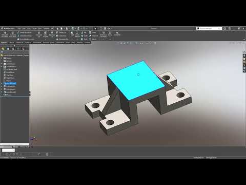
Getting Started with SolidWorks 3D: A Beginner’s Guide to Isometric Modeling

Wednesday, September 30, 2026

Whether you are an aspiring mechanical engineer, a product designer, or a 3D printing enthusiast, learning computer-aided design (CAD) is an essential skill. Among the leading tools in the industry, SolidWorks 3D stands out for its powerful parametric features and intuitive user interface. In this beginner-friendly guide, we will explore the fundamentals of isometric 3D modeling and show you how to turn basic 2D concepts into detailed three-dimensional models.

What is Isometric 3D Modeling?

Isometric modeling allows designers to represent three-dimensional objects clearly on a two-dimensional plane. Unlike perspective drawings, isometric views maintain parallel lines, making it significantly easier to measure dimensions accurately and visualize the spatial relationships between different features of a component. Mastering this technique provides a strong foundation for technical drawings, complex engineering assemblies, and rapid prototyping.

Core Steps to Create Your First Model

Getting started with SolidWorks 3D does not have to be overwhelming. By following a structured workflow, you can build clean, fully constrained models in just a few straightforward steps:

  1. Select the Orientation: Begin by choosing the appropriate reference plane (Front, Top, or Right) based on how your object will be viewed or manufactured.
  2. Draft the Base Sketch: Use basic geometry tools like lines, rectangles, and arcs to outline the primary shape. Always anchor your sketch to the origin point to maintain design stability.
  3. Apply Smart Dimensions and Constraints: Define precise measurements and geometric relations (such as parallel, perpendicular, or concentric) so your sketch is fully defined.
  4. Extrude into 3D: Use the Extruded Boss/Base feature to transform your 2D outline into a solid 3D object by specifying the required depth.
  5. Refine the Design: Add secondary features such as fillets, chamfers, or extruded cuts to finalize the detailed geometry of your part.

Key Practices for CAD Beginners

To maximize your modeling efficiency when using SolidWorks 3D, keep your initial sketches as simple as possible. It is always better to build up a complex part through multiple simple features rather than creating one overly complicated sketch. Furthermore, utilizing geometric relations instead of excessive manual dimensioning will save you valuable time when making future design revisions.

Start practicing today by recreating basic isometric shapes, and lay the groundwork for your journey into advanced 3D design!

Continue Reading | ความคิดเห็น

Popular Posts Today

 
Support : 3Dcadbrowser | Grabcad | 3Dcontentcentral | D | E | F | G
Copyright © 2028. Engineering 3DCad Appication - All Rights Reserved