Cad 3D Category

Showing posts with label 3D BIM. Show all posts

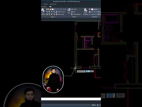
How to Easily Replicate Floor Plans in 3D BIM using Revit

Sunday, November 22, 2026
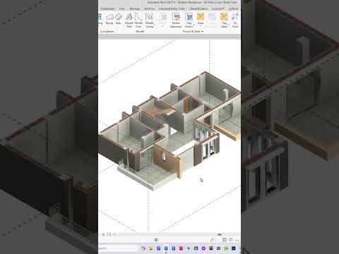
Transitioning from traditional 2D drafting to a comprehensive 3D BIM workflow can drastically improve architectural design efficiency. Autodesk Revit offers powerful tools that allow designers to quickly replicate existing 2D floor plans into dynamic 3D representations. Whether you are working with imported CAD files, image overlays, or multi-story buildings, mastering these essential Revit tips and tricks will significantly streamline your modeling process.

Preparing Your Floor Plan Baseline

Before diving into 3D replication, ensure your base drawing is clean and properly aligned. If you are importing an external DWG file or image reference: - Clean the CAD File: Purge unnecessary layers and line work from your CAD drawing before linking it into Revit. - Establish Project Levels: Set exact floor-to-floor heights in your Revit elevation views prior to drawing walls. - Pin Your References: Once linked, pin the baseline floor plan to prevent accidental movement while modeling.

Seamlessly Replicating 2D Plans into 3D

Revit provides intuitive features to transform flat drawings into intelligent parametric elements within a 3D BIM environment.

  1. Tracing with Pick Lines: Instead of manually drawing walls from scratch, use the Pick Lines tool while placing walls, doors, and windows over your linked floor plan. This guarantees high precision without tedious measuring.
  2. Multi-Story Replication: If your project features repetitive floor layouts—such as residential towers or office spaces—model one master level completely. Then, use the Copy to Clipboard tool and select Aligned to Selected Levels to instantly replicate the floor plan across multiple stories.

Best Practices for Revit Efficiency

To maintain high performance and accurate building data throughout the project lifecycle, keep these tips in mind: - Utilize Model Groups: Group recurring unit layouts so changes made on one floor automatically update across all identical levels. - Verify Alignments in 3D Views: Frequently toggle between 2D plan views and 3D perspectives to identify misaligned walls or structural clashes early. - Clean Up Geometry: Use the Join Geometry and Trim/Extend tools to maintain clean wall intersections and accurate room areas.

Conclusion

Replicating floor plans in Revit isn't just about speed; it's about unlocking the full potential of 3D BIM for enhanced collaboration, accurate visual representations, and efficient project documentation. Start implementing these quick techniques today to elevate your architectural modeling workflow!

Continue Reading | ความคิดเห็น

The Ultimate Guide to 3D BIM and Modern Civil Engineering

Saturday, November 7, 2026

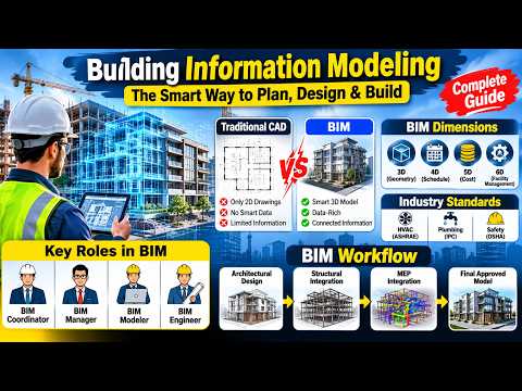
Building Information Modeling (BIM) has completely revolutionized the architecture, engineering, and construction (AEC) industry. Gone are the days of relying solely on 2D blueprints and disconnected hand-drawn schematics. Today, modern infrastructure projects demand intelligent, collaborative workflows that reduce errors, save costs, and streamline management from initial design to final operation.

What is 3D BIM?

At its core, 3D BIM is the digital representation of the physical and functional characteristics of a structure. Unlike traditional CAD drafting, 3D BIM goes beyond simple geometric shapes by embedding rich parametric data into every element. This allows civil engineers, architects, and contractors to visualize structural components, spatial relationships, and material properties in a real-time digital environment. As a result, cross-functional teams can perform clash detection early, catching design errors long before construction begins on-site.

Expanding the Dimensions: 4D and 5D BIM

While three-dimensional modeling lays the essential foundation, advanced BIM integration incorporates time and budget dimensions into the workflow:

  • 4D BIM (Time & Scheduling): Adds project scheduling and timeline data to the visual model. This enables engineers to simulate the construction process step-by-step, optimize logistical workflows, and prevent site delays.
  • 5D BIM (Cost & Quantity Takeoff): Integrates financial tracking and real-time cost estimation. Any alteration in the structural design automatically updates material quantities and budget calculations, helping managers maintain financial control.

Key Benefits for Civil Engineers

Adopting 3D BIM empowers civil engineering professionals to work faster, smarter, and with greater precision. Main benefits include:

  • Seamless Collaboration: A single source of truth ensures structural, mechanical, and electrical teams work off the same updated data.
  • Rework Reduction: Virtual clash detection drastically decreases costly field modifications and rework.
  • Enhanced Sustainability: Detailed spatial data helps optimize energy usage and material consumption for eco-friendly building practices.

Conclusion

Mastering Building Information Modeling is no longer just an advantage—it is an essential requirement for modern engineering. By combining 3D geometry with 4D scheduling and 5D cost management, construction professionals can deliver complex projects efficiently, on time, and within budget.

Continue Reading | ความคิดเห็น

How to Create Bridge Pillars and Abutments Using 3D BIM in Autodesk Revit

Monday, October 26, 2026

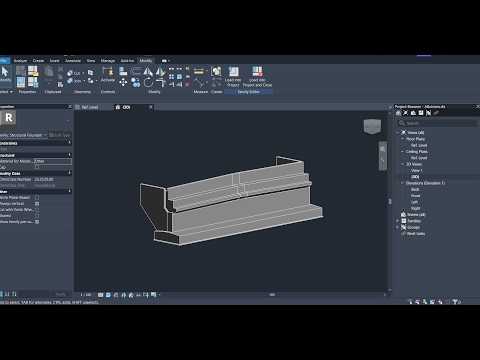
Modern civil engineering relies heavily on digital workflows to ensure precision, structural integrity, and efficient project delivery. When designing complex transportation infrastructure like highways and bridges, utilizing 3D BIM (Building Information Modeling) methodologies has become the industry standard. In bridge engineering, modeling critical substructure elements—such as piers, pillars, and abutments—demands accurate geometry and seamless structural coordination.

Why Use Autodesk Revit for Bridge Substructures?

Piers and abutments serve as the backbone of bridge structures, bearing heavy loads and transferring them safely to the foundation. Traditional 2D CAD drafting often falls short in visualizing complex geometric intersections and reinforcement details. By implementing 3D BIM workflows inside Autodesk Revit, structural engineers and students alike can construct dynamic, parametric digital models that automatically update across all plans, elevations, and section views.

Key advantages include: - Clash Detection: Spot structural spatial conflicts early in the design phase. - Parametric Flexibility: Easily adjust pier heights, footing sizes, and abutment dimensions. - Accurate Quantity Takeoffs: Generate precise concrete and structural schedules automatically.

Key Steps to Modeling Piers and Abutments

  1. Establish Levels and Grids: Begin by setting up project datum elements, including reference elevations for foundation footings, pier caps, and bridge deck levels.
  2. Model Abutments with Precision: Use parametric wall or structural foundation families to build the end-support abutments, ensuring proper wingwall alignment and bearing seat placement.
  3. Construct Support Pillars: Place middle piers and columns, tailoring their geometry—whether cylindrical, rectangular, or tapered—to withstand environmental and structural load demands.
  4. Integrate Reinforcement and Annotations: Apply structural rebar detailing inside the 3D model to create comprehensive construction documentation.

Final Thoughts

Whether you are a student showcasing an academic bridge construction project or a professional structural designer, mastering 3D BIM with Autodesk Revit significantly elevates the quality and accuracy of your work. Embracing these advanced digital workflows ultimately bridges the gap between conceptual design and real-world construction success.

Continue Reading | ความคิดเห็น

Mastering Site Coordinates: Survey Point and Project Base Point in 3D BIM

Friday, October 16, 2026

In the world of modern construction and digital design, precision is everything. When working within a 3D BIM environment, understanding how to position your model correctly can mean the difference between a seamless project execution and a costly coordination nightmare. To achieve total accuracy, every professional must master three core elements: the Internal Origin, the Project Base Point, and the Survey Point.

The Internal Origin: The Hidden Anchor

Every digital project begins at the Internal Origin. Think of this as the absolute (0,0,0) coordinate of your modeling software's universe. While it is often invisible, this point serves as the fixed basis for all geometry. When linking models from various disciplines—such as structural, MEP, and architectural—ensuring they share a common understanding of the Internal Origin is the first step toward a clash-free project.

Project Base Point: Your Building’s Local Reference

The Project Base Point is used to establish a local coordinate system relative to the building itself. It is typically placed at a recognizable spot on the structure, such as a major column intersection or a building corner. This point allows the design team to measure distances and offsets within the specific site context. Mastering the placement of this point is essential for effective 3D BIM workflows, as it simplifies the communication of dimensions and levels during the design and documentation phases.

Survey Point: Connecting to the Real World

While the Project Base Point handles the building, the Survey Point represents the real world. This point is usually tied to a physical landmark or a geographic coordinate provided by a professional surveyor (using Northing, Easting, and Elevation). By correctly setting the Survey Point, you ensure that your digital model sits exactly where it should on the Earth’s surface. This is vital for site planning, topography integration, and ensuring that the building aligns perfectly with existing infrastructure.

Why Coordinate Accuracy Matters

Whether you are using Revit, Navisworks, Tekla, or Archicad, aligning these coordinate points is the foundation of successful BIM coordination. Misalignment leads to "floating" buildings or overlapping structures when files are merged for interference checking. By mastering these coordinate systems, you ensure your 3D BIM project is built on a solid foundation of accuracy, allowing for better collaboration across all stakeholders and a smoother transition from the screen to the construction site.

Continue Reading | ความคิดเห็น

AI Meets 3D BIM: How GPT Control of FreeCAD Changes CAD Modeling Forever

Saturday, October 3, 2026

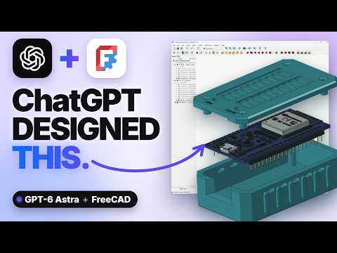
Imagine giving an AI total control over your CAD software and watching it design a complex, 3D-printable ESP32 enclosure without providing a single numerical dimension. That is precisely what happened when GPT-6 Astra was linked directly to FreeCAD. By utilizing contextual reasoning and spatial logic, the AI acted like an experienced engineer, creating an accurate, functional model from scratch.

This milestone isn't just exciting for 3D printing enthusiasts; it signals a massive paradigm shift for industrial design and modern 3D BIM (Building Information Modeling) processes.

AI as the New CAD Driver

Traditionally, Computer-Aided Design (CAD) requires tedious manual input: drawing sketches, constraining dimensions, and meticulously applying features like extrusions, fillets, or shell functions. However, connecting an advanced model like GPT-6 Astra directly to an open-source platform like FreeCAD fundamentally alters this dynamic.

Instead of demanding manual tolerance entries, the AI interprets functional requirements. It understands the physical layout of an ESP32 microcontroller, infers necessary port cutouts, ventilation grids, and mounting standoffs, and generates the Python scripts required to build the physical geometry autonomously.

Transforming 3D BIM and Engineering Workflows

The true power of autonomous AI design lies in its infinite scalability. When scaled up to large-scale infrastructure and architectural engineering, integrating generative intelligence into a 3D BIM pipeline can automate repetitive drafting tasks, optimize structural material usage, and proactively identify design flaws.

Just as GPT-6 Astra deduced the necessary spatial geometry for a small circuit board, AI-driven BIM software will soon generate full structural assemblies based purely on building code compliance, climate data, and functional space requirements. Engineers will transition from manual drafters to high-level strategic directors.

Bridging Generative AI and Physical Manufacturing

The seamless link between AI logic and parametric CAD tools demonstrates that generative models are rapidly expanding beyond text and image synthesis into functional, real-world geometry. As these intelligent systems continue to evolve, their inclusion in digital twin technologies and 3D BIM environments will radically accelerate hardware prototyping and modern construction.

The era of typing a descriptive prompt and receiving a fully parametric, production-ready 3D model is no longer a distant vision—it is officially reality.

Continue Reading | ความคิดเห็น

Popular Posts Today

 
Support : 3Dcadbrowser | Grabcad | 3Dcontentcentral | D | E | F | G
Copyright © 2028. Engineering 3DCad Appication - All Rights Reserved