Cad 3D Category

Showing posts with label AutoCAD 3D. Show all posts

Master Multiline Text: A Step-by-Step Guide for AutoCAD 3D Users

Sunday, November 1, 2026
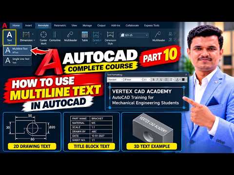
Clear communication is essential when creating precise engineering drawings and architectural plans. Whether you are drafting basic 2D floor plans or working on complex AutoCAD 3D models, adding detailed annotations, dimensions, and explanatory notes ensures your designs are correctly understood. One of the most powerful annotation tools available in AutoCAD is the Multiline Text (MTEXT) feature.

In this quick guide, you will learn how to efficiently use Multiline Text to streamline your documentation workflow.

Why Choose Multiline Text Over Single Line Text?

Unlike Single Line Text, Multiline Text (MTEXT) gives you complete control over paragraph formatting, word wrapping, alignment, and styling. Key advantages include:

  • Advanced Formatting: Adjust font styles, text height, colors, and line spacing within a single text block.
  • Bullets and Lists: Easily create numbered or bulleted specifications directly on your technical drawings.
  • Columns and Margins: Organize extensive notes into clean, readable multi-column layouts without manual line breaks.

Step-by-Step: How to Use Multiline Text in AutoCAD

Using the MTEXT command is straightforward and fits seamlessly into any workflow, whether you are focusing on traditional drafting or detailed AutoCAD 3D projects.

  1. Activate the Command: Type MTEXT or the shortcut MT into the command line and press Enter. Alternatively, select Multiline Text from the Annotation panel on the Home ribbon tab.
  2. Specify the Boundary: Click once in your workspace to set the first corner of your text frame, then drag and click again to set the opposite corner. This bounding box defines the width of your text paragraph.
  3. Enter Your Content: The Text Editor contextual tab will automatically open. Type your technical notes, descriptions, or instructions inside the frame.
  4. Format the Appearance: Highlight any portion of your text to change its font style, height, justification, or insert special symbols (such as degree, diameter, or plus/minus symbols).
  5. Close and Save: Click Close Text Editor on the ribbon or click anywhere outside the text boundary box to apply the changes.

Tips for Better Annotation Management

To maintain consistency across large AutoCAD 3D assemblies or standard floor plans, always utilize defined Text Styles (STYLE command). Additionally, placing your MTEXT on dedicated annotation layers allows you to manage object visibility and plotting properties effortlessly.

Conclusion

Mastering Multiline Text is a fundamental skill for any CAD designer looking to produce clean, professional-grade documentation. Start incorporating MTEXT into your daily routine to save time and elevate the quality of your AutoCAD projects today!

Continue Reading | ความคิดเห็น

Essential AutoCAD 3D Basic Settings: A Step-by-Step Beginner's Guide

Wednesday, October 21, 2026

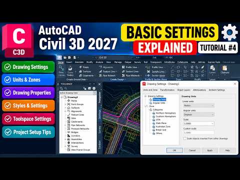
Starting any civil engineering or design project requires a solid foundation. Before you begin drawing lines, generating surfaces, or designing infrastructure, configuring your software workspace correctly is critical. Getting familiar with basic configuration options in Civil 3D 2027 ensures your workflows remain efficient, accurate, and standardized across your team.

Understanding Drawing Settings, Units, and Zones

Setting up your workspace properly prevents costly errors later in the project lifecycle. In modern AutoCAD 3D civil engineering workflows, defining the correct units (feet vs. meters) and drawing scales is the first step toward project accuracy.

Equally important is assigning the correct geographical zone and coordinate system. Setting up geographic transformation settings guarantees that your design aligns seamlessly with real-world spatial data, aerial imagery, and GIS databases.

Managing Drawing Properties and Metadata

Organizing your project data is just as vital as the technical drafting itself. Through the Drawing Properties menu, you can configure crucial metadata, including:

  • Project Title and Description
  • Author and Client details
  • Custom property fields for drawing automation

Maintaining accurate drawing properties streamlines document control, simplifies multi-user collaboration, and automates title block data across your drawing sheets.

Mastering Styles for Visual Consistency

Styles control how drawing elements—such as surfaces, alignments, points, and corridors—are displayed on your screen and in final print outputs. By mastering AutoCAD 3D object and label styles, you can maintain company design standards while keeping your drawing performance optimized. Setting up standard styles early allows you to quickly toggle visual displays on or off, helping you focus on design details without cluttering your drawing area.

Final Thoughts

Taking the time to configure drawing settings, units, properties, and visual styles before modeling will save you hours of troubleshooting later. A properly configured template in AutoCAD 3D gives you complete control over your project data, visual presentation, and spatial accuracy. Make sure to establish these basic settings as a standard practice for every new project!

Continue Reading | ความคิดเห็น

How to Change UCS in AutoCAD 3D: A Step-by-Step Guide for Beginners

Sunday, October 11, 2026

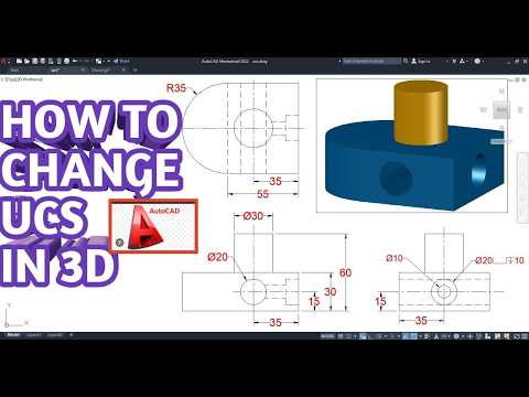
For anyone making the leap from 2D drafting to 3D design, learning how to navigate three-dimensional space is essential. One of the fundamental skills every beginner must master is controlling the User Coordinate System (UCS). Transitioning to AutoCAD 3D becomes significantly easier once you understand how to manipulate the UCS to draw on any plane or surface with confidence.

In this guide, we will break down what the UCS is, how to change it, and how to combine it with core modeling commands like Extrude and Subtract.

What is the UCS in AutoCAD?

By default, AutoCAD uses the World Coordinate System (WCS), which fixes the X and Y axes on a flat horizontal plane, with the Z-axis pointing vertically upward. However, when building complex 3D objects, you often need to draw shapes directly onto angled or vertical surfaces.

This is where changing the UCS comes in. By repositioning the User Coordinate System, you set any face or plane as your active X-Y working plane, allowing you to sketch 2D geometry directly on existing 3D models.

How to Change the UCS Easily

Changing the UCS is straightforward once you know the right steps. Here is a simple process to align your working plane:

  1. Type UCS in the Command Line: Press Enter to activate the command.
  2. Select the 'Face' Option: Type F (or choose "Face" from the prompt) and press Enter.
  3. Select a Surface: Click on the specific 3D face where you want to create your new sketch.
  4. Accept the Alignment: Press Enter to confirm the new orientation.

Now, your grid and drawing plane align perfectly with the selected face, showing why changing the UCS is a crucial skill for efficient AutoCAD 3D modeling.

Combining UCS with Extrude and Subtract

Once your UCS is properly aligned to a face, you can start creating complex features using basic 3D commands:

  • Extrude (EXT): Draw a 2D profile (like a circle or rectangle) on your new UCS plane, then use the EXTRUDE command to push or pull it into a 3D solid shape.
  • Subtract (SU): If you want to create holes, slots, or cutouts, place an extruded object intersecting your main model and use the SUBTRACT command to remove it from the base object.

Final Thoughts

Mastering coordinate systems is the key to unlocking a seamless workflow in 3D design. By learning how to reorient your working plane and combining it with basic extrusion and subtraction tools, mastering these core features will significantly boost your productivity in AutoCAD 3D. Keep practicing on different objects, and you will be modeling complex parts in no time!

Continue Reading | ความคิดเห็น

Building the Ultimate LEGO Hogwarts Castle in AutoCAD 3D

Sunday, September 27, 2026

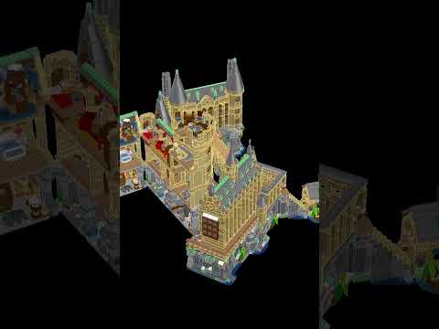
For fans of the Wizarding World and LEGO building, combining multiple Hogwarts sets into one massive, cohesive display is the ultimate dream. However, planning a mega-structure that seamlessly merges sets like 76426, 76435, 76454, 76463, and 76473 requires incredible spatial awareness and precision. That is where the power of AutoCAD 3D comes into play, bringing complex magical architecture to life in a digital workspace before physical construction even begins.

Merging Modular Magic into One Grand Design

Combining individual LEGO Harry Potter sets can be challenging due to varying connection points, heights, and architectural layouts. By recreating these popular sets digitally, builders can experiment with different custom layouts without taking up vast amounts of physical table space. Modeling iconic locations—from the Great Hall to the soaring spires—allows you to visualize the full grandeur of the castle, testing how each modular piece connects to form a unified Hogwarts layout.

Precision Engineering Meets Creative Fantasy

Why use professional drafting software for a brick project? Utilizing AutoCAD 3D offers unparalleled accuracy when aligning complex geometry, stud measurements, and intricate structural details. Designers can easily check spatial tolerances, adjust proportions, and rotate the model to view Hogwarts Castle from every conceivable angle. This digital blueprinting process ensures that every tower, courtyard, and hidden chamber fits together in perfect structural harmony.

Take Your LEGO Projects to the Next Level

Whether you are a master builder planning your next real-world room display or a CAD enthusiast looking for an exciting passion project, modeling multi-set builds in AutoCAD 3D bridges the gap between fantasy and technical design. It transforms standard building instructions into a truly interactive, three-dimensional architectural masterpiece.

Continue Reading | ความคิดเห็น

Popular Posts Today

 
Support : 3Dcadbrowser | Grabcad | 3Dcontentcentral | D | E | F | G
Copyright © 2028. Engineering 3DCad Appication - All Rights Reserved