
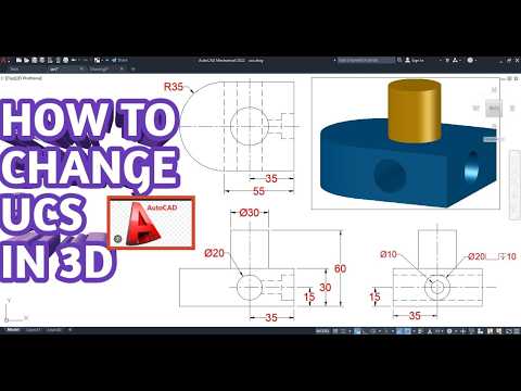
For anyone making the leap from 2D drafting to 3D design, learning how to navigate three-dimensional space is essential. One of the fundamental skills every beginner must master is controlling the User Coordinate System (UCS). Transitioning to AutoCAD 3D becomes significantly easier once you understand how to manipulate the UCS to draw on any plane or surface with confidence.
In this guide, we will break down what the UCS is, how to change it, and how to combine it with core modeling commands like Extrude and Subtract.
What is the UCS in AutoCAD?
By default, AutoCAD uses the World Coordinate System (WCS), which fixes the X and Y axes on a flat horizontal plane, with the Z-axis pointing vertically upward. However, when building complex 3D objects, you often need to draw shapes directly onto angled or vertical surfaces.
This is where changing the UCS comes in. By repositioning the User Coordinate System, you set any face or plane as your active X-Y working plane, allowing you to sketch 2D geometry directly on existing 3D models.
How to Change the UCS Easily
Changing the UCS is straightforward once you know the right steps. Here is a simple process to align your working plane:
- Type
UCSin the Command Line: Press Enter to activate the command. - Select the 'Face' Option: Type
F(or choose "Face" from the prompt) and press Enter. - Select a Surface: Click on the specific 3D face where you want to create your new sketch.
- Accept the Alignment: Press Enter to confirm the new orientation.
Now, your grid and drawing plane align perfectly with the selected face, showing why changing the UCS is a crucial skill for efficient AutoCAD 3D modeling.
Combining UCS with Extrude and Subtract
Once your UCS is properly aligned to a face, you can start creating complex features using basic 3D commands:
- Extrude (
EXT): Draw a 2D profile (like a circle or rectangle) on your new UCS plane, then use theEXTRUDEcommand to push or pull it into a 3D solid shape. - Subtract (
SU): If you want to create holes, slots, or cutouts, place an extruded object intersecting your main model and use theSUBTRACTcommand to remove it from the base object.
Final Thoughts
Mastering coordinate systems is the key to unlocking a seamless workflow in 3D design. By learning how to reorient your working plane and combining it with basic extrusion and subtraction tools, mastering these core features will significantly boost your productivity in AutoCAD 3D. Keep practicing on different objects, and you will be modeling complex parts in no time!
