Cad 3D Category

Showing posts with label CAD Modeling. Show all posts

Fast-Track Your CAD Skills: Designing a Modern Lamp in Inventor 3D

Monday, November 16, 2026

Whether you are a seasoned CAD professional or just starting your journey into mechanical design, watching a complex object come to life in seconds is always inspiring. In a recent quick-build demo, an intricate desk lamp was transformed from a blank digital canvas into a detailed model in just 11 minutes—and then condensed into a captivating 45-second time-lapse video.

Using the robust feature set of Inventor 3D, this project highlights how fast, efficient, and precise modern digital prototyping can be when you master core CAD techniques.

Bringing a Lamp to Life: The Design Process

Designing a functional product like a lamp requires a smart combination of sketching, parametric constraints, and feature management. The 11-minute build demonstrates a streamlined modeling workflow:

  • Base and Frame Creation: Starting with clean 2D sketches, simple geometric profiles are extruded and revolved to form a sturdy base and support arm.
  • Lampshade Geometry: Utilizing shell and loft operations, the lampshade is crafted to maintain realistic wall thickness while achieving a sleek aesthetic.
  • Detailing and Finishing: Mechanical joints, hardware details, and realistic material appearances are applied to give the model a polished, production-ready look.

Why Practice Speed Modeling in Inventor 3D?

While accuracy is paramount in engineering, engaging in short, timed modeling challenges is one of the best ways to sharpen your digital modeling proficiency. Practicing quick builds in Inventor 3D offers several key benefits:

  1. Hotkey Mastery: You naturally learn essential keyboard shortcuts and navigation tools, drastically speeding up daily tasks.
  2. Logical Feature Trees: Speed modeling forces you to plan your history tree efficiently so components remain easy to edit later.
  3. Rapid Prototyping: Being able to quickly turn a rough sketch into a 3D visualization helps communicate ideas effectively to clients or team members.

Elevate Your Design Workflow

A 45-second visual teaser is great for quick inspiration, but true mastery comes from following along step-by-step. If you are ready to build this model from scratch, check out the full step-by-step tutorial. Mastering tools within Inventor 3D will transform your design approach, allowing you to bring your creative concepts into reality faster than ever before.

Continue Reading | ความคิดเห็น

From Physical Part to CAD: Unlocking the Power of 3D Scanning in Reverse Engineering

Tuesday, October 27, 2026

Have you ever wondered how to accurately recreate complex mechanical components when original CAD files are unavailable? Whether you are redesigning legacy hardware or replacing worn-out industrial machinery, reverse engineering provides the ultimate solution. By leveraging modern 3D scanning techniques alongside specialized software, engineers can quickly turn physical objects into fully editable, parametric CAD models.

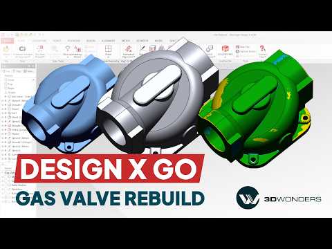
In this workflow guide, we explore how a complex mechanical gas valve can be accurately reconstructed using Geomagic Design X Go.

Bridging the Gap Between Physical Parts and Digital CAD

Converting raw scan data into usable digital geometry used to be a tedious, manual process. Today, tools like Geomagic Design X Go streamline the entire Scan-to-CAD pipeline. The software accepts dense polygon meshes generated by high-resolution scanners and provides powerful tools to extract feature curves, surfaces, and solid bodies.

When dealing with intricate components such as a gas valve—complete with internal flow channels, precision threads, and mounting flanges—3D scanning captures exact real-world dimensions without destructive testing or manual measurement errors.

Reconstructing the Gas Valve: Key Steps in the Workflow

  1. Data Import and Alignment: The process begins by importing the triangular mesh of the gas valve. The scan is aligned to a logical coordinate system using geometric primitives like planes and cylinders extracted directly from the mesh.
  2. Feature Extraction: Automated region segmentation identifies key functional areas such as valve seats and port openings. Sketch planes are then positioned to extract precise cross-sectional profiles.
  3. Solid Modeling: Using standard parametric modeling operations—such as extrusions, revolves, and sweeps—the full 3D geometry of the gas valve is built step-by-step over the reference mesh.

Why Reverse Engineering Matters for Manufacturing

Integrating robust 3D scanning solutions into your product development workflow significantly reduces prototyping time, eliminates measurement bottlenecks, and enables precise modification of legacy parts. Software like Geomagic Design X Go ensures that your reverse-engineered models maintain a complete parametric feature tree, making future modifications fast and intuitive.

Whether you are restoring critical infrastructure or improving product design, combining digital scan data with powerful CAD reconstruction software is the fastest path from a physical part to a production-ready model.

Continue Reading | ความคิดเห็น

How to Tame Desk Clutter with a Smart 3D Printing Magnet Pen

Tame the Clutter on Your Craft Bench

If you frequently work with small craft supplies, electronics, or tiny hardware, you know how easily loose magnets can end up scattered across your workspace. They stick to unwanted tools, get lost under papers, and turn an organized desk into a frustrating headache. Fortunately, makers are finding simple, practical ways to solve this problem—and the answer lies in custom tool creation.

Why a Magnet Pen is a Game-Changer

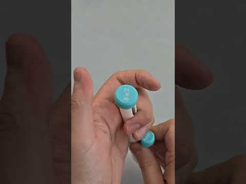
Enter the magnet pen: a clever DIY tool designed to hold, dispense, and organize small neodymium magnets with absolute precision. Instead of fumbling through a jumbled pile of sticking magnets, this ergonomic dispenser lets you pick up and place magnets exactly where you need them. Whether you are assembling miniature models, completing home repairs, or working on intricate electronic gadgets, a dedicated magnet applicator saves time and keeps your workstation tidy.

Through practical 3D printing, makers can design custom internal channels that align magnets in a single row. Paired with a simple spring or plunger mechanism, the pen delivers one magnet at a time, ensuring your workflow remains smooth and hassle-free.

Designing and Manufacturing Your Own Tool

Creating your own magnet dispenser is easier than ever thanks to accessible CAD software and high-speed desktop printers. By leveraging modern 3D printing technology, you can customize the barrel size to fit the exact diameter and thickness of the magnets you use most often.

  • Precision Fit: Model tight tolerances so the magnets slide smoothly without jamming.
  • Ergonomic Design: Add textured grips or a pocket clip for everyday convenience.
  • Material Selection: Standard PLA or PETG works perfectly for quick, durable, and cost-effective builds.

Upgrade Your DIY Workflow Today

Functional prints are among the most rewarding projects in the maker community. By combining smart 3D modeling with 3D printing, you can instantly turn chaotic loose parts into a streamlined, professional tool setup. Say goodbye to messy magnets once and for all, and upgrade your workshop with a custom-printed magnet pen today!

Continue Reading | ความคิดเห็น

Master 3D CAD: The Ultimate Professional Upgrade Guide for AutoCAD Users

Thursday, September 10, 2026

Transitioning from traditional 2D drafting to modern 3D CAD modeling is one of the most impactful upgrades a design professional can make. While 2D drawings have served as the industry standard for decades, today’s complex engineering and architectural demands require greater clarity, precision, and efficiency. Elevating your skills to three dimensions isn't just a technical upgrade—it is a major business advantage.

Why Upgrade from 2D to 3D Design?

Making the jump to 3D modeling fundamentally transforms how you deliver projects. Unlike flat, two-dimensional plans, three-dimensional models offer an immersive view of your design, allowing you to identify spatial conflicts, design flaws, and structural errors long before construction or manufacturing begins.

Key business benefits include: - Enhanced Visualization: Communicate your design intent clearly to clients and non-technical stakeholders who may struggle to interpret 2D schematics. - Fewer Costly Errors: Automated clash detection drastically reduces rework on the job site or shop floor. - Faster Revisions: Updating a single 3D component automatically reflects across all associated views, drawings, and documentation.

Essential Steps for a Seamless Transition

Moving from 2D lines and polylines to solid geometry requires a shift in how you conceptualize your work. Here is how to make the upgrade as smooth as possible:

  1. Shift Your Conceptual Mindset: Stop thinking in terms of separate flat views (Plan, Elevation, Section) and start building objects as unified, solid components.
  2. Master Navigation and the UCS: Get comfortable orbiting around objects and manipulating the User Coordinate System (UCS). Understanding workplanes is crucial for precise placement in a three-dimensional space.
  3. Start with Basic Primitives: Begin by creating simple shapes like boxes, cylinders, and extrusions. Once you master combining these simple solids, you can advance to more complex parametric features.

Unlocking the Full Potential of 3D CAD

Adopting a robust 3D CAD workflow allows you to extract precise 2D documentation, generate photorealistic renderings, and produce accurate bills of materials—all from a single source model. By investing the time to upgrade your AutoCAD skill set, you position yourself and your firm at the forefront of modern design, delivering superior quality while saving time and resources.

Continue Reading | ความคิดเห็น

Mastering 3D CAD to Slicer Precision for Professional 3D Printing

Transitioning a digital design into a physical object is the core of modern engineering and rapid prototyping. However, professionals frequently encounter a frustrating issue during this process: dimensional discrepancies between the original 3D CAD model and the sliced file prepared for 3D printing. Understanding and resolving these errors is critical for delivering high-precision components in professional projects.

Why Discrepancies Occur Between CAD and Slicer

When you export a parametric 3D CAD design into a mesh format like STL or OBJ, the software converts smooth curves into a network of flat triangles. This tessellation process inevitably introduces geometric approximations.

When this mesh file is imported into a slicer, additional variables come into play. Slicer settings—such as layer height, extrusion width, wall ordering, and material shrinkage—can further distort the original dimensions. In professional applications where tight tolerances are non-negotiable, even a 0.1mm deviation can prevent PCB assemblies or enclosure snaps from fitting together properly.

How to Eliminate Dimensional Errors

To bridge the gap between your digital design and the final 3D print, follow these key strategies:

  • Optimize Export Resolution: When saving your model in your design software, fine-tune the chord deviation and angle tolerance settings. High-density mesh exports reduce polygon approximation errors.
  • Calibrate Horizontal Expansion: Most modern slicers offer "Horizontal Expansion" or "Slicing Tolerance" features. Adjusting these settings helps compensate for wall swelling caused by plastic flow.
  • Account for Material Shrinkage: Filament types like ABS or PETG shrink as they cool. Scale your model slightly in the slicer to offset predicted material contraction.

Relying on Professional Fabrication Services

For complex, mission-critical projects where desktop printers fall short, turning to commercial manufacturing platforms can save both time and resources. Professional fabrication services, such as PCBWay, provide industrial-grade 3D printing and PCB prototyping solutions. By using high-end additive manufacturing equipment, these platforms ensure that your complex 3D CAD assemblies are manufactured with incredible accuracy, eliminating the trial-and-error phase of slicer calibration.

Conclusion

Achieving perfect alignment between your CAD design and slicer software is essential for professional manufacturing success. By refining your export settings, calibrating slicer offsets, and leveraging professional fabrication partners, you can ensure that your final printed parts match your engineering specifications every single time.

Continue Reading | ความคิดเห็น

Popular Posts Today

 
Support : 3Dcadbrowser | Grabcad | 3Dcontentcentral | D | E | F | G
Copyright © 2028. Engineering 3DCad Appication - All Rights Reserved