Cad 3D Category

Showing posts with label Engineering Design. Show all posts

Mastering Precision: How to Create a Centerline Between Two Polylines in Civil 3D

Friday, October 23, 2026
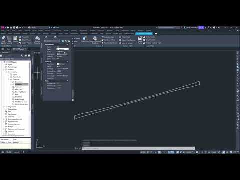
In the world of civil engineering and infrastructure design, precision is the foundation of every successful project. Whether you are mapping out a new roadway, defining a utility corridor, or establishing property boundaries, finding the exact midpoint between two linear features is a frequent necessity. If you are using Civil 3D, you don’t have to rely on manual offsets or tedious geometric calculations to find your center.

Why Automate Your Centerline Creation?

Manually drawing a centerline between two irregular polylines is not only time-consuming but also prone to human error. Even a slight deviation can impact earthwork calculations or drainage slopes. By leveraging the automated geometric tools within Civil 3D, you ensure that your design remains mathematically accurate and dynamically linked to your existing site data.

Step-by-Step: Generating a Centerline

Creating a centerline between two existing polylines is a straightforward process that can significantly speed up your drafting phase. Follow these steps to achieve a clean result:

  1. Prepare Your Source Data: Ensure that the two polylines representing your edges (such as a curb line or a ditch) are clean and do not contain unnecessary overlapping vertices.
  2. Access the Command: While there are various ways to achieve this, many professionals use the "Centerline" command found under the Annotate or Modify tabs, or specific geometric tools within the transparent commands.
  3. Select the Boundaries: Select your first polyline and then the second. The software will calculate the average distance between all corresponding points to generate a new line exactly in the middle.
  4. Refine the Result: Once the line is generated, you can convert it into an Alignment if you need to create profiles or cross-sections later in your design process.

Pro-Tips for Better Accuracy

To get the best results, ensure that your polylines are drawn in the same direction. If one polyline starts at the north and the other at the south, the software may struggle to calculate the relationship between the vertices. Additionally, simplifying the polyline (reducing the number of vertices) before creating the centerline can result in a much smoother, more manageable line.

Mastering these small but essential workflows in Civil 3D will not only improve the accuracy of your technical drawings but also save you hours of manual rework. Start implementing this technique today to streamline your site design and focus on what really matters—building better infrastructure.

Continue Reading | ความคิดเห็น

Beyond the Model: How to Create Flawless Technical Drawings in 3D Software

Saturday, September 26, 2026

Creating a stunning 3D model is a rewarding milestone for any designer or engineer, but does your design process stop there? For most real-world applications, the answer is a resounding no. Once your part is fully modeled, the next critical challenge begins: converting that digital asset into a clear, precise, and professional technical drawing.

Why Technical Drawings Are Still Essential

Even in an era dominated by advanced digital manufacturing, 2D technical drawings remain the universal language of the engineering world. A detailed blueprint communicates exact dimensions, geometric tolerances, surface finishes, and material specifications that a standalone digital model simply cannot convey on a factory floor. Without proper documentation, even the most innovative design risks misinterpretation, costly manufacturing errors, and delayed production schedules.

Seamlessly Transitioning from 3D to 2D

Mastering this transition is where your professional skills truly shine. Modern 3D software solutions are engineered to make this process efficient and accurate, allowing designers to generate associative 2D views directly from their solid models. This direct link ensures that whenever you modify your 3D geometry, your technical drawing updates automatically—saving valuable time and eliminating manual drafting errors.

To ensure your technical blueprints are manufacturing-ready, consider these key strategies:

  • Choose the Right Layout: Always include standard orthographic projection views (front, top, side) along with a shaded isometric view to give fabricators an instant visual reference.
  • Utilize Section and Detail Views: Avoid cluttering primary views with hidden lines. Use section cuts to expose internal features and detail views to magnify complex areas.
  • Apply Clean Dimensioning: Focus on clarity rather than clutter. Apply dimensions logically, avoiding redundancy and leveraging automated drafting tools inside your 3D software.

Take Your CAD Skills to the Next Level

Creating clear technical drawings isn't just a administrative chore; it is a vital skill that bridges concept and physical production. By leveraging the full drafting capabilities of your preferred 3D software, you can transform complex parts into clear, actionable technical drawings that suppliers and machinists can build with total confidence. Stop letting your designs end at the 3D modeling phase—start creating complete blueprints that bring your ideas to life.

Continue Reading | ความคิดเห็น

Beyond Organization: Unlock the True Power of Layers in CAD Software

Friday, September 18, 2026

When designing complex technical drawings, using modern CAD software is essential for precision and speed. However, many engineers and designers only use CAD layers as digital file folders to keep line work tidy. While organization is a major benefit, layers offer far more value than simple categorization.

If you want to optimize your workflow, improve design accuracy, and save hours of editing time, understanding the full potential of CAD layers is crucial. Here is why layers are the true backbone of efficient engineering design.

Effortless Editing of Complex Drawings

As technical drawings grow in detail, modifying specific components becomes increasingly difficult. Without proper layering, selecting a single line can accidentally alter surrounding elements. By assigning different components—such as dimensions, annotations, structural framing, or electrical wiring—to distinct layers, you can lock, freeze, or hide non-relevant details. This allows you to edit precise sections safely and rapidly without visual clutter getting in your way.

Streamlined Review and Collaboration

In collaborative engineering projects, multiple stakeholders need to review different aspects of the same design. Architects may focus on spatial layouts, while structural engineers focus on load-bearing components. Utilizing layer controls within your CAD software allows you to customize views for different audiences in seconds. Instead of creating separate drawing files for each discipline, you can simply toggle layer visibility on or off, ensuring every team member reviews only the information relevant to them.

Enhanced Drawing Management and Standardized Output

Layers do more than manage visibility; they also control line weights, colors, linetypes, and plot settings. Setting up standard layer properties ensures that your final prints and PDF exports maintain a uniform visual hierarchy across all project sheets. Furthermore, turning off complex, unneeded layers while actively drafting significantly improves software performance, reducing display lag on large-scale blueprints.

Conclusion

CAD layers are much more than a neat filing system—they are a powerful tool for control, performance, and seamless communication. Ultimately, mastering layer management is one of the easiest ways to level up your drafting efficiency and maximize the value of your CAD software. Rethink your layer strategy today, and watch your design workflow become faster, cleaner, and far more professional.

Continue Reading | ความคิดเห็น

Unlocking the Power of 3D CAD: Quick AutoCAD Tricks Every Designer Should Know

Friday, September 11, 2026

In today’s fast-paced engineering and architectural industries, digital drafting is no longer just about 2D lines and basic shapes. Mastering 3D CAD software like AutoCAD has become an essential skill for professionals looking to bring complex ideas to life with precision and speed. Whether you are a beginner or a seasoned designer, optimizing your workflow can make a massive difference in your daily productivity.

Why 3D CAD Skills Matter in Modern Design

Transitioning from traditional 2D drafting to 3D CAD modeling opens up endless possibilities. It allows designers to visualize spatial relationships, detect structural errors early in the planning phase, and produce photo-realistic renders for clients. Beyond aesthetics, working in three dimensions ensures greater accuracy, making project handoffs smoother across multidisciplinary teams.

Essential AutoCAD Productivity Hacks

To create stunning models efficiently, you don't just need knowledge—you need speed. Here are a few quick tips to streamline your AutoCAD workflow:

  • Utilize Key Command Shortcuts: Relying on keyboard shortcuts like EXT (Extrude), PRESSPULL, and UNION saves valuable time compared to navigating menu icons manually.
  • Master Visual Styles: Switch seamlessly between Conceptual, Shaded, and Realistic views to inspect your model's geometry without slowing down system performance.
  • Implement Dynamic Blocks: Create parametric components that can be resized or altered quickly without redrawing elements from scratch.
  • Use the ViewCube Efficiently: Navigate your workspace effortlessly by customizing your ViewCube settings for fast orientation and angle adjustments.

Elevate Your Design Potential

Integrating these quick habits into your daily routine will drastically reduce drafting time while improving the quality of your output. As 3D CAD technology continues to evolve, staying updated with efficient modeling techniques will keep you ahead of the curve in the competitive design landscape. Start practicing these tricks today and transform your AutoCAD project workflow!

Continue Reading | ความคิดเห็น

Master 3D CAD: The Ultimate Professional Upgrade Guide for AutoCAD Users

Thursday, September 10, 2026

Transitioning from traditional 2D drafting to modern 3D CAD modeling is one of the most impactful upgrades a design professional can make. While 2D drawings have served as the industry standard for decades, today’s complex engineering and architectural demands require greater clarity, precision, and efficiency. Elevating your skills to three dimensions isn't just a technical upgrade—it is a major business advantage.

Why Upgrade from 2D to 3D Design?

Making the jump to 3D modeling fundamentally transforms how you deliver projects. Unlike flat, two-dimensional plans, three-dimensional models offer an immersive view of your design, allowing you to identify spatial conflicts, design flaws, and structural errors long before construction or manufacturing begins.

Key business benefits include: - Enhanced Visualization: Communicate your design intent clearly to clients and non-technical stakeholders who may struggle to interpret 2D schematics. - Fewer Costly Errors: Automated clash detection drastically reduces rework on the job site or shop floor. - Faster Revisions: Updating a single 3D component automatically reflects across all associated views, drawings, and documentation.

Essential Steps for a Seamless Transition

Moving from 2D lines and polylines to solid geometry requires a shift in how you conceptualize your work. Here is how to make the upgrade as smooth as possible:

  1. Shift Your Conceptual Mindset: Stop thinking in terms of separate flat views (Plan, Elevation, Section) and start building objects as unified, solid components.
  2. Master Navigation and the UCS: Get comfortable orbiting around objects and manipulating the User Coordinate System (UCS). Understanding workplanes is crucial for precise placement in a three-dimensional space.
  3. Start with Basic Primitives: Begin by creating simple shapes like boxes, cylinders, and extrusions. Once you master combining these simple solids, you can advance to more complex parametric features.

Unlocking the Full Potential of 3D CAD

Adopting a robust 3D CAD workflow allows you to extract precise 2D documentation, generate photorealistic renderings, and produce accurate bills of materials—all from a single source model. By investing the time to upgrade your AutoCAD skill set, you position yourself and your firm at the forefront of modern design, delivering superior quality while saving time and resources.

Continue Reading | ความคิดเห็น

Popular Posts Today

 
Support : 3Dcadbrowser | Grabcad | 3Dcontentcentral | D | E | F | G
Copyright © 2028. Engineering 3DCad Appication - All Rights Reserved