Cad 3D Category

Showing posts with label CAD Tutorial. Show all posts

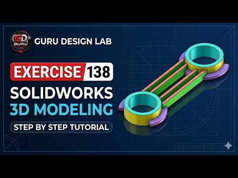
Master 3D CAD Modeling: SOLIDWORKS Mechanical Part Tutorial (Exercise 138)

Saturday, November 21, 2026
Mastering modern engineering design requires consistent practice and hands-on experience with industry-standard software. Whether you are taking your first steps in engineering or looking to refine your parametric design skills, working through practical mechanical exercises is the best way to grow.

In this tutorial brought to you by Guru Design Lab, we walk you step-by-step through SOLIDWORKS Exercise 138, taking your modeling techniques from beginner level all the way to advanced precision.

Why Practice Mechanical Part Modeling?

Transitioning from simple 2D sketches to complex solid geometries can be challenging. Working on structured design challenges helps you master essential modeling operations such as extruded bosses, cuts, fillets, and revolve features.

Honing your skills through hands-on 3D CAD exercises allows you to understand design intent, optimize component geometry, and maintain clean feature trees that are easy to edit later in the design cycle.

Key Techniques Covered in Exercise 138

In this exercise, you will learn how to approach a technical drawing efficiently and translate dimensions into an accurate 3D model:

  • Defining Base Sketches: Learn how to select the optimal sketching plane and use geometric relations to keep your sketches fully defined.
  • Main Feature Creation: Apply basic and advanced extrusion techniques to build the primary volume of the mechanical part.
  • Precision Material Removal: Master cut-extrude and hole features to create internal pockets and mounting holes precisely where needed.
  • Detailing & Finishing: Add fillets and chamfers to smooth edges, reduce stress concentration, and give your model a professional finish.

Tips for an Efficient Modeling Workflow

To build accurate models quickly in any 3D CAD environment, always plan your steps before drawing the first line. Start with the largest base feature and progressively add complex details. Keep your sketches simple and rely on feature operations rather than overly crowded single sketches.

By following along with this guided video tutorial, you will streamline your overall 3D CAD workflow and gain the confidence needed to tackle complex mechanical assemblies in your professional project work. Watch the step-by-step video above, grab your dimensions, and start modeling today!

Continue Reading | ความคิดเห็น

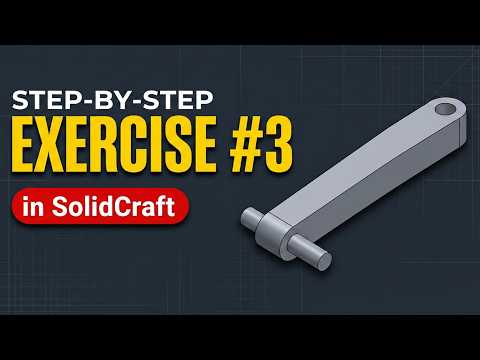
Master 3D Design: A Step-by-Step Guide to SolidCraft Beginner Exercise #3

Saturday, November 14, 2026

Are you ready to take your computer-aided design (CAD) skills to the next level? Whether you are a complete novice or looking to refresh your foundational skills, practicing with structured exercises is the best way to build confidence in digital manufacturing. In this tutorial, we dive into SolidCraft Beginner Exercise #3 to help you master essential 3D modeling techniques.

Why Practice Basic CAD Exercises?

Understanding fundamental geometric concepts, extrusions, and cutouts is critical before tackling complex engineering projects. Dedicated practice models allow you to understand core design workflows, shortcut keys, and parametric modeling principles. By working through hands-on exercises, you transform theoretical design knowledge into practical, real-world expertise.

Key Concepts Covered in Exercise #3

This beginner exercise focuses on combining accurate 2D sketches with basic 3D features. Here is what you will practice during this tutorial:

  • 2D Profile Sketching: Creating precise sketches using lines, arcs, dimensions, and geometric constraints.
  • Extruded Boss/Base: Converting flat two-dimensional profiles into solid three-dimensional objects.
  • Extruded Cut Features: Removing material accurately to create holes, slots, and custom recesses.
  • Plane Selection: Learning how to choose the ideal sketch plane (Front, Top, or Right) to maintain an efficient design tree.

Step-by-Step Workflow for Success

To get the most out of your SolidCraft practice, follow a systematic modeling approach:

  1. Analyze the Drawing: Take a moment to review all technical dimensions and identify the primary base feature.
  2. Start the Base Sketch: Select the appropriate plane and draw the main outline, ensuring your sketch is fully constrained with dimensions.
  3. Generate the Solid: Apply the main extrusion feature to create the base geometry.
  4. Add Secondary Features: Create additional sketches on existing faces to cut holes or add smaller features until the part matches the reference model.

Start Modeling Today

Consistent practice is the key to becoming a proficient 3D designer. By mastering fundamental projects like this SolidCraft guide, you build a strong foundation for advanced surface modeling and mechanical design. Fire up your software, follow along with the video tutorial, and keep expanding your CAD portfolio today!

Continue Reading | ความคิดเห็น

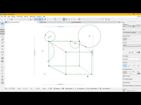
Mastering ArchiCAD 3D: Powerful Tips to Create and Modify Architectural Drawings

Friday, November 6, 2026

Whether you are an aspiring architect, an experienced draftsman, or a BIM enthusiast, mastering digital design tools is essential for modern architectural workflows. Among the leading Building Information Modeling (BIM) software, ArchiCAD 3D stands out as a flexible, powerful solution that seamlessly connects 2D drafting with stunning three-dimensional visualization.

In this practical guide, we will explore key tips and techniques to help you effectively create and modify architectural drawings, boosting both your design precision and modeling speed.

Setting Up and Creating Drawings Efficiently

Starting a project with a clean workflow saves hours of rework later. When creating new drawings, begin by establishing precise grid systems and story settings. Utilizing parametric tools—such as smart walls, slabs, doors, and windows—allows you to build an intelligent design right from the first click.

Instead of viewing 2D drafting and 3D modeling as separate steps, leverage the full capabilities of ArchiCAD 3D. Every wall or object you place in the 2D floor plan view automatically generates corresponding geometry in the 3D window, ensuring complete model accuracy and consistency.

Modifying and Fine-Tuning Your Design

Architecture is an iterative process, and modifying your drawings swiftly is just as important as creating them. ArchiCAD offers robust editing tools designed to keep your work dynamic:

  • Pet Palette Shortcuts: Master the context-sensitive Pet Palette to offset, stretch, curve, or rotate elements on the fly.
  • Trim and Split Tools: Keep geometry clean by using quick keyboard shortcuts to trim unwanted lines or split complex shapes.
  • Parameter Transfer: Use the Eyedropper and Syringe tools (Alt and Ctrl/Cmd + Alt) to instantly copy and inject properties from one element to another across your layout.

Bridging 2D Drafting and 3D Visualization

One of the key advantages of working within ArchiCAD 3D is the ability to inspect your design instantly in a realistic spatial environment. Switching back and forth between 2D floor plans and 3D views helps you spot spatial errors, verify material alignments, and make modifications directly in the 3D workspace.

By integrating both 2D drafting tips and 3D editing techniques into your daily routine, you will dramatically streamline your architectural documentation process and deliver professional results in less time.

Conclusion

Building an efficient modeling workflow requires practice, but mastering basic creation and modification features will quickly elevate your architectural projects. Apply these essential tips to your next project and unlock the full potential of your design workspace!

Continue Reading | ความคิดเห็น

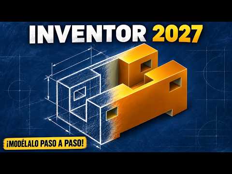
Mastering Inventor 3D: How to Model Parts and Prepare Them for 3D Printing

Monday, November 2, 2026

Additive manufacturing has revolutionized how we bring physical products to life, but every great print starts with a precise computer-aided design (CAD) model. If you are new to design software, learning Inventor 3D modeling is one of the most effective ways to master mechanical design and rapid prototyping. In this guide, we will explore the step-by-step process of creating a part from scratch in Autodesk Inventor 2027 and preparing it for seamless 3D printing.

Step 1: Interpreting Geometry and 2D Sketching

Before creating any solid geometry, you need to analyze the part's basic shape, symmetry, and key dimensions. Start by opening a new part file in Autodesk Inventor 2027 and selecting an appropriate work plane (such as the XY or XZ plane). Translate your blueprint or physical measurements into a clean 2D sketch using fundamental drawing tools like lines, circles, and arcs. Always apply geometric constraints and precise dimensional values to ensure your sketch is fully constrained, which prevents unwanted deformation as your model grows more complex.

Step 2: Transforming 2D Sketches into Solid Parts

Once your 2D sketch is fully defined, it is time to convert it into a solid object. The Extrude and Revolve tools allow you to add mass quickly, while cut operations enable you to create precise holes, slots, and complex internal cutouts. By taking advantage of Inventor 3D design features, you can easily apply fillets and chamfers to smooth sharp edges, reduce stress concentrations, or improve the visual appeal of your component. Building your parametric features logically ensures that any future modification takes only seconds to update.

Step 3: Exporting Your Model for 3D Printing

With your geometry complete, the final step is exporting the file for additive manufacturing. Navigate to the file export menu and select a universally recognized 3D printing format, such as STL or 3MF. Before saving, check your export resolution settings: choosing high refinement yields smoother curves on your physical print, whereas low refinement can result in visible faceting. Once exported, load the file into your preferred slicer software to generate the G-code for your 3D printer.

Final Thoughts

Developing proficiency in Inventor 3D design bridges the gap between digital concepts and real-world physical objects. By following a structured workflow—from sketch interpretation to final mesh export—you can reliably produce functional, high-quality models ready for 3D printing.

Continue Reading | ความคิดเห็น

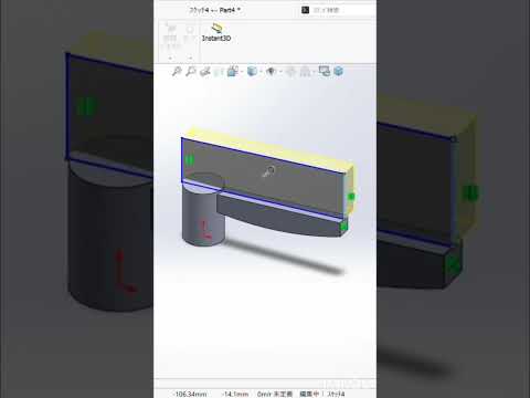
Mastering Mechanical Design: A Deep Dive into 3D CAD with SolidWorks (Day 49)

Sunday, October 25, 2026

In the rapidly evolving world of industrial design, the ability to transform a conceptual sketch into a functional mechanical component is a vital skill. For many engineers and designers, the journey toward mastery is paved with consistent practice and the right tools. As we reach "Day 49" of our design challenge, we shift our focus toward the intricate details of machine part modeling, showcasing why SolidWorks remains the gold standard for professionals worldwide.

The Power of Precision with 3D CAD

Modern engineering demands more than just aesthetic appeal; it requires mathematical precision and structural integrity. Using 3D CAD software allows designers to simulate real-world conditions, test tolerances, and visualize complex assemblies before a single piece of hardware is ever manufactured. This digital-first approach significantly reduces production costs and accelerates the time-to-market for new machinery.

In today’s project, we explore the nuances of parametric modeling. By defining specific constraints and relationships between different geometric features, we create a robust model that can be easily updated or modified. Whether you are designing a simple bracket or a complex engine component, mastering these 3D CAD techniques ensures that your designs are both scalable and accurate.

Progressing Through the Day 49 Milestone

Reaching the halfway point of a 100-day challenge is a significant milestone. At this stage, the focus shifts from basic sketching to advanced features such as swept bosses, lofted cuts, and complex fillets. The "Day 49" model highlights the intersection of form and function, focusing on a machine part that requires specific load-bearing properties.

As you navigate through the SolidWorks interface, you begin to realize that the software is not just a drawing tool—it is an extension of the engineer's mind. Every extrude and revolve operation is a step toward solving a mechanical puzzle. For those looking to transition from a hobbyist to a professional level, consistently practicing with 3D CAD is the most effective way to build the muscle memory required for high-speed, high-accuracy modeling.

Conclusion: Elevate Your Design Workflow

The journey of a thousand models begins with a single sketch. By committing to a daily practice routine, you not only learn the software but also develop a deeper understanding of mechanical geometry. As we continue to push the boundaries of what is possible in the digital workspace, staying updated with the latest tools and techniques is essential for any aspiring designer.

Stay tuned as we continue this journey toward day 100, refining our skills and unlocking the full potential of industrial-grade modeling software.

Continue Reading | ความคิดเห็น

Popular Posts Today

 
Support : 3Dcadbrowser | Grabcad | 3Dcontentcentral | D | E | F | G
Copyright © 2028. Engineering 3DCad Appication - All Rights Reserved