Cad 3D Category

Showing posts with label SolidWorks. Show all posts

Mastering Mechanical Assembly: Step-by-Step Pipe Wrench in SolidWorks 3D

Thursday, October 1, 2026
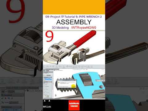
Designing mechanical components requires precision, especially when transitioning from individual part creation to complex mechanical assemblies. If you want to enhance your engineering portfolio and refine your CAD skills, learning how to build functional mechanisms is essential. In this project tutorial, we dive deep into assembling a classic mechanical tool: the Pipe Wrench using SolidWorks 3D.

Essential Steps for the Pipe Wrench Assembly

Assembling a pipe wrench involves several moving parts that must interact seamlessly, including the hook jaw, heel jaw, adjustment nut, and main handle structure. To achieve an accurate and functional model, precision mating and proper mechanical constraints are crucial.

Here are the core concepts covered in this project: - Inserting Base Components: Begin by positioning the main handle structure, establishing it as the fixed component to ground your assembly. - Applying Standard Mates: Utilize concentric, parallel, and coincident mates to align the movable jaws and threaded mechanisms correctly. - Simulating Mechanical Motion: Set up advanced or mechanical mates to create realistic sliding motion for the hook jaw and rotational movement for the adjustment nut.

Why Practice Complex Assemblies in SolidWorks 3D?

Working on practical, real-world projects like a pipe wrench allows engineers, designers, and students to move beyond basic sketch tools. Utilizing SolidWorks 3D for assembly design helps you identify potential component interferences, evaluate physical clearances, and understand how individual mechanical features function together in an industrial setting.

By mastering these fundamental assembly techniques, you gain a strong advantage when tackling advanced product design, mechanical engineering tasks, or complex hardware prototyping.

Conclusion

Whether you are a beginner looking to understand basic mate conditions or an intermediate user refining your CAD workflow, assembling a pipe wrench is an outstanding practice exercise. Follow along with our complete video tutorial to master mechanical mates and elevate your modeling expertise in SolidWorks 3D today!

Continue Reading | ความคิดเห็น

Mastering Advanced Sketching: Pro Tips and Tricks for CAD Software Users

Sunday, September 13, 2026

Sketching is the fundamental building block of any 3D model. Whether you are designing a simple bracket or a complex mechanical assembly, the efficiency and stability of your final product depend heavily on how you approach the initial 2D layout. For professionals and hobbyists alike, mastering the nuances of your CAD software is the secret to moving from basic designs to high-level engineering.

Rethinking Your Sketching Strategy

Many users fall into the habit of using the same basic tools for every project. However, advanced sketching is about more than just drawing lines and circles; it is about intent and flexibility. Instead of manually dimensioning every single entity, advanced users leverage geometric relations to define how shapes interact. By "thinking a different way," you can create sketches that are easier to modify later, preventing your model from "breaking" when a single dimension changes.

Efficiency Through Advanced Techniques

When working with professional-grade CAD software, speed is often just as important as accuracy. One of the best ways to improve your workflow is to utilize shortcut keys and mouse gestures for common sketch entities. Furthermore, exploring non-traditional methods—such as using construction geometry to drive complex patterns or employing the "Path Length" dimension—can solve design challenges that standard sketching simply cannot handle.

Another "pro tip" involves minimizing the number of entities in a single sketch. By breaking complex parts into several simpler features, you maintain better control over the design intent. This modular approach is a hallmark of an expert user who knows how to harness the full potential of their digital tools.

Why Mastering These Skills Matters

The transition from a beginner to an advanced user requires a shift in mindset. It’s about understanding the underlying logic of the program. By mastering these advanced tips and tricks, you aren't just drawing; you are programmatically defining a physical object.

As you continue to refine your skills within your CAD software, you will find that your design process becomes more intuitive and significantly faster. This not only makes you a more valuable engineer or designer but also allows you to focus more on the creative aspects of innovation rather than the technical hurdles of the interface. Keep experimenting with different sketching methods, and you will soon see a massive improvement in your 3D modeling precision.

Continue Reading | ความคิดเห็น

Master 3D CAD: A Beginner's Guide to Complex Mechanical Design in SolidWorks

Thursday, September 10, 2026

Transitioning from simple geometric shapes to intricate engineering components can feel intimidating, but mastering 3D CAD is much easier than you think when you have the right approach. SolidWorks remains one of the premier software tools used by engineers, industrial designers, and makers worldwide. Learning how to navigate its powerful feature set while building complex mechanical parts is a crucial milestone for anyone serious about digital design.

Why Focus on Complex Mechanical Parts?

Understanding how to create detailed components in a modern 3D CAD environment bridges the gap between basic technical drawing and real-world manufacturing. While beginner exercises often focus on simple extrusions, realistic mechanical parts require a deeper understanding of sketch relations, feature hierarchy, and spatial reasoning. By tackling multi-step models early in your learning journey, you gain the confidence needed to solve actual engineering challenges and create assembly-ready models.

Key Steps to Modeling Intricate Components in SolidWorks

Building a complex mechanical part comes down to breaking down the object into manageable geometric steps:

  1. Establish a Clean Base Sketch: Always start with a fully defined 2D sketch using precise dimensions and geometric relations. A strong foundation prevents your model from breaking when edits are made later.
  2. Build the Primary Geometry: Utilize core features such as extruded bosses, revolves, and swept cuts to construct the primary volume of the part before adding minor features.
  3. Refine with Secondary Features: Apply fillets, chamfers, draft angles, and hole wizards to give your component realistic mechanical features and smooth transitions.
  4. Inspect and Modify: Utilize native evaluation tools to check mass properties, feature trees, and design intent to ensure your model is optimized for production.

Elevate Your Design Workflow Today

Consistent practice is the key to gaining proficiency. By following structured tutorials and repeatedly applying these fundamental workflow steps, you will quickly transform raw ideas into professional, production-ready models. Take your skills to the next level with modern 3D CAD tools, accept the challenge of complex mechanical design, and bring your engineering ideas to life!

Continue Reading | ความคิดเห็น

Download AAA System 3D CAD Model | Multi-Format Compatibility

Preview Image

Enhance your design workflow with the high-quality AAA System 3D CAD Model. Designed for mechanical engineers, CAD specialists, and industrial designers, this asset offers seamless integration into your preferred engineering environment.

Key Features & Highlights

  • High Compatibility: Fully supports native and neutral file imports across leading engineering platforms.
  • Precise Geometry: Optimized topology ideal for assembly modeling, detailed rendering, and digital prototyping.
  • Streamlined Workflow: Save valuable engineering time by integrating ready-to-use component geometry directly into your digital mockups.

Supported CAD Packages

Downloadable formats are structured for smooth import into:

  • Dassault Systèmes SolidWorks & CATIA
  • Autodesk AutoCAD & Inventor
  • PTC Creo (Pro/ENGINEER)
  • Siemens NX
  • Spatial ACIS and standard generic 3D formats

Ideal for mechanical engineering projects, system layout designs, and simulation analysis.


Continue Reading | ความคิดเห็น

A-10 Warthog 3D CAD Model: Multi-Format Download for Engineers

Wednesday, September 9, 2026

Preview Image

Enhance your aerospace design projects with this highly detailed A-10 Warthog (Fairchild Republic A-10 Thunderbolt II) 3D CAD Model. Built for precision and versatile software integration, this 3D asset is ideal for aerospace engineers, military aircraft enthusiasts, simulation developers, and CAD designers requiring accurate external geometry.

Key Features & Highlights:

  • Multi-Platform Compatibility: Ready to import into major industrial CAD software.
  • Accurate External Airframe: Detailed representation of the iconic close-air-support attack aircraft, including twin-engine layout and signature airframe structure.
  • Flexible Workflows: Perfect for visualization, spatial layout studies, rendering, and aviation reference modeling.

Supported CAD Software Formats:

This model is compatible with a wide range of parametric and direct modeling software, including:

  • SolidWorks & CATIA
  • Autodesk Inventor & AutoCAD
  • PTC Creo / Pro-ENGINEER
  • Siemens NX
  • ACIS and standard neutral 3D file formats

Download this versatile A-10 Warthog CAD file today to streamline your modeling and simulation workflow.


Continue Reading | ความคิดเห็น

Popular Posts Today

 
Support : 3Dcadbrowser | Grabcad | 3Dcontentcentral | D | E | F | G
Copyright © 2028. Engineering 3DCad Appication - All Rights Reserved