Cad 3D Category

ABB IRB 2600ID-8/2.00 Industrial Robot 3D CAD Model Free Download

Friday, September 11, 2026

Preview Image

Enhance your automated cell design and simulation workflows with the official 3D CAD model of the ABB IRB 2600ID-8/2.00 industrial robot arm. Featuring Integrated Dressing (ID) technology, this highly versatile 6-axis manipulator is engineered for high-precision applications including arc welding, material handling, and machine tending.

Key Technical Specifications:

  • Payload Capacity: 8 kg
  • Reach: 2.00 meters
  • Axis Count: 6-axis articulated manipulator
  • Design Advantage: Integrated hose package inside the upper arm and wrist for extended process cable life and compact footprint footprint clearance.

Supported CAD Software Formats:

This 3D model is compatible with all major parametric and direct modeling software platforms, including:

  • SolidWorks (.SLDPRT, .SLDASM)
  • AutoCAD (.DWG, .DXF)
  • Autodesk Inventor (.IPT, .IAM)
  • PTC Creo / Pro/ENGINEER (.PRT, .ASM)
  • Siemens NX & Solid Edge
  • CATIA V5/V6
  • Universal Formats: STEP (.stp), IGES (.igs), ACIS (.sat)

Download this accurate CAD file to streamline your robotic system integration, collision detection, and plant layout simulation today.


Continue Reading | ความคิดเห็น

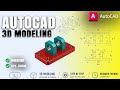
Mastering 3D CAD: How to Model a Mechanical Mounting Bracket in AutoCAD

In the evolving world of mechanical engineering, the ability to transform a 2D concept into a functional 3D model is an essential skill. One of the best ways to sharpen these skills is through practical, hands-on exercises that replicate real-world components. In this guide, we explore the process of creating a mechanical mounting bracket, a fundamental tool in the world of 3D CAD.

Starting with the Foundation: The Base Plate

Every great mechanical model begins with a solid foundation. For this mounting bracket project, we start by constructing a rectangular base plate. In AutoCAD, this involves using primitive shapes or extruding a 2D rectangle to a specific thickness. By assigning a distinct color—such as a vibrant red—designers can easily differentiate between various components within a complex assembly. This level of visual clarity is one of the many advantages of using professional 3D CAD software for mechanical practice.

Precision Engineering and Mounting Holes

A mounting bracket is only as functional as its connectivity. The next critical step in the modeling process is the addition of four precise mounting holes located at the corners of the base. This requires careful measurement and the use of the "Subtract" command to create clean, accurate voids. This stage of the project emphasizes the importance of geometric constraints and precision, ensuring that the digital part would theoretically fit perfectly into a real-world mechanical assembly.

Why Practice Work is Essential

Whether you are a student or an aspiring engineer, consistent practice is the key to proficiency. Transitioning from basic shapes to complex mechanical parts helps users understand the workspace, the Z-axis, and the various shortcuts that speed up the design process. Utilizing 3D CAD for these practice sessions allows you to experiment with different materials, lighting, and viewing angles before moving on to more intricate industrial designs.

Conclusion

Modeling a mechanical mounting bracket is more than just a basic exercise; it is a stepping stone to mastering industrial design. By following these fundamental principles in AutoCAD, you can build a strong portfolio of mechanical parts and gain the confidence needed to tackle large-scale engineering projects. Keep practicing, keep designing, and unlock the full potential of your technical creativity!

Continue Reading | ความคิดเห็น

ABB IRB 1600ID 6-Axis Industrial Robot 3D CAD Model

Preview Image

Download ABB IRB 1600ID 6-Axis Industrial Robot CAD Model

Optimize your automated manufacturing cell simulations and machinery layouts with the ABB IRB 1600ID 6-axis industrial robot 3D CAD model. Featuring Integrated Dressing (ID), the IRB 1600ID is designed specifically for high-precision arc welding, material handling, and tight-space manufacturing applications.

Key CAD Model Features:

  • High Precision Geometry: Accurately modeled 6-axis articulation suitable for reachability and collision detection analysis.
  • Integrated Process Cable Routing: Internal hose package routing for accurate digital twin representation.
  • Universal Integration: Ready for import into all major CAD, CAM, and simulation platforms.

Supported File Formats:

This model is compatible with top CAD systems including SolidWorks, Autodesk Inventor, AutoCAD, PTC Creo (Pro/ENGINEER), Siemens NX, CATIA, ACIS (.sat), STEP, and IGES.

Applications:

  • Robotic workcell layout and reach analysis
  • Tooling and fixture integration
  • Factory automation and digital twin simulation

Continue Reading | ความคิดเห็น

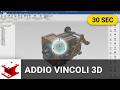
Mastering IronCAD’s TriBall: The Secret to High-Speed 3D CAD Modeling

In the fast-paced world of industrial design, efficiency is the divide between meeting a deadline and falling behind. While traditional modeling software often requires navigating complex menus and setting up tedious constraints, IronCAD offers a refreshing alternative. At the heart of this streamlined workflow is a single, legendary tool: the TriBall.

What is the TriBall?

The TriBall is often cited by engineers as the most versatile positioning tool in the industry. It is a multi-functional graphical interface that allows users to manipulate parts and assemblies with unprecedented speed. Whether you need to move, rotate, mirror, or pattern an object, the TriBall serves as your all-in-one command center.

By integrating this tool into your 3D CAD workflow, you eliminate the need for dozens of separate commands. Instead of hunting for a "Mirror" or "Array" button, you simply activate the TriBall and perform the action directly on the object in the 3D space.

Efficiency in Under 30 Seconds

The true power of the TriBall lies in its simplicity. As demonstrated in our recent "30-second" showcase, complex movements that would take minutes in other software packages can be completed in moments.

For instance, if you need to position a bolt within a specific hole, you don't need to apply three different geometric mates. You can simply drag the TriBall to the center of the hole, and the part snaps into place with mathematical precision. This intuitive approach makes 3D CAD design feel less like programming and more like physical assembly, allowing your creativity to flow without technical interruptions.

Why It Changes the Game for Designers

Most 3D CAD platforms rely heavily on history-based constraints, which can become "brittle" and break when a design changes. IronCAD’s TriBall operates with a more flexible philosophy. It provides the precision of a professional engineering tool with the ease of use typically found in graphic design software.

Key benefits include: * Linear and Radial Patterns: Create complex arrays of parts in seconds. * Precision Rotation: Tilt and turn components to exact angles without external references. * Dynamic Mirroring: Instantly flip components across any axis or plane.

Conclusion

If you are looking to accelerate your design cycle, mastering the TriBall is the best place to start. It isn't just a feature; it’s a fundamental shift in how designers interact with their models. By reducing the number of clicks required for every task, IronCAD empowers you to spend less time managing software and more time innovating.

Ready to see it in action? Explore the power of IronCAD and transform your engineering process today.

Continue Reading | ความคิดเห็น

ABB IRB 120 Industrial Robot Arm 3D CAD Model

Preview Image

Download a high-precision 3D CAD model of the ABB IRB 120, ABB’s smallest 6-axis industrial robot arm designed for flexible, compact, and high-speed material handling and assembly applications.

Key Model Features & Specifications:

  • Payload Capacity: 3 kg (4 kg for vertical wrist orientation)
  • Reach: 580 mm maximum reach radius
  • Axis Count: 6-axis articulated robot arm
  • Application Suitability: Automation workcell design, collision detection, reachability analysis, and spatial planning.

Supported CAD Formats:

This 3D model is compatible with major engineering and CAD software packages, including:

  • SolidWorks (.sldprt, .sldasm)
  • Autodesk Inventor (.ipt, .iam)
  • CATIA V5 / V6
  • PTC Creo / Pro/ENGINEER
  • Siemens NX
  • AutoCAD & Universal Formats (STEP, IGES, ACIS, SAT)

Ideal for mechanical design engineers, robotics integrators, and automation designers building industrial simulation environments.


Continue Reading | ความคิดเห็น

Master 3D CAD: A Beginner's Guide to Complex Mechanical Design in SolidWorks

Thursday, September 10, 2026

Transitioning from simple geometric shapes to intricate engineering components can feel intimidating, but mastering 3D CAD is much easier than you think when you have the right approach. SolidWorks remains one of the premier software tools used by engineers, industrial designers, and makers worldwide. Learning how to navigate its powerful feature set while building complex mechanical parts is a crucial milestone for anyone serious about digital design.

Why Focus on Complex Mechanical Parts?

Understanding how to create detailed components in a modern 3D CAD environment bridges the gap between basic technical drawing and real-world manufacturing. While beginner exercises often focus on simple extrusions, realistic mechanical parts require a deeper understanding of sketch relations, feature hierarchy, and spatial reasoning. By tackling multi-step models early in your learning journey, you gain the confidence needed to solve actual engineering challenges and create assembly-ready models.

Key Steps to Modeling Intricate Components in SolidWorks

Building a complex mechanical part comes down to breaking down the object into manageable geometric steps:

  1. Establish a Clean Base Sketch: Always start with a fully defined 2D sketch using precise dimensions and geometric relations. A strong foundation prevents your model from breaking when edits are made later.
  2. Build the Primary Geometry: Utilize core features such as extruded bosses, revolves, and swept cuts to construct the primary volume of the part before adding minor features.
  3. Refine with Secondary Features: Apply fillets, chamfers, draft angles, and hole wizards to give your component realistic mechanical features and smooth transitions.
  4. Inspect and Modify: Utilize native evaluation tools to check mass properties, feature trees, and design intent to ensure your model is optimized for production.

Elevate Your Design Workflow Today

Consistent practice is the key to gaining proficiency. By following structured tutorials and repeatedly applying these fundamental workflow steps, you will quickly transform raw ideas into professional, production-ready models. Take your skills to the next level with modern 3D CAD tools, accept the challenge of complex mechanical design, and bring your engineering ideas to life!

Continue Reading | ความคิดเห็น

ABB 1000kVA Transformer 3D CAD Model | Download for SolidWorks, AutoCAD & CATIA

Preview Image

Download a high-precision ABB 1000kVA Transformer 3D CAD Model optimized for electrical engineering, industrial plant layout, and power distribution design. This CAD asset allows engineering teams to accurately plan spatial constraints, cable routing, and mounting configurations prior to installation.

Supported File Formats

  • SolidWorks (.sldprt, .sldasm)
  • AutoCAD (.dwg, .dxf)
  • Autodesk Inventor (.ipt)
  • PTC Creo / Pro/ENGINEER
  • Siemens NX & CATIA
  • ACIS (.sat), STEP (.stp), & IGES (.igs)

Key Applications

  • Substation design and spatial clearance analysis
  • MEP and industrial facility plant layout modeling
  • Electrical switchgear and enclosure integration

Continue Reading | ความคิดเห็น

Master 3D CAD: The Ultimate Professional Upgrade Guide for AutoCAD Users

Transitioning from traditional 2D drafting to modern 3D CAD modeling is one of the most impactful upgrades a design professional can make. While 2D drawings have served as the industry standard for decades, today’s complex engineering and architectural demands require greater clarity, precision, and efficiency. Elevating your skills to three dimensions isn't just a technical upgrade—it is a major business advantage.

Why Upgrade from 2D to 3D Design?

Making the jump to 3D modeling fundamentally transforms how you deliver projects. Unlike flat, two-dimensional plans, three-dimensional models offer an immersive view of your design, allowing you to identify spatial conflicts, design flaws, and structural errors long before construction or manufacturing begins.

Key business benefits include: - Enhanced Visualization: Communicate your design intent clearly to clients and non-technical stakeholders who may struggle to interpret 2D schematics. - Fewer Costly Errors: Automated clash detection drastically reduces rework on the job site or shop floor. - Faster Revisions: Updating a single 3D component automatically reflects across all associated views, drawings, and documentation.

Essential Steps for a Seamless Transition

Moving from 2D lines and polylines to solid geometry requires a shift in how you conceptualize your work. Here is how to make the upgrade as smooth as possible:

  1. Shift Your Conceptual Mindset: Stop thinking in terms of separate flat views (Plan, Elevation, Section) and start building objects as unified, solid components.
  2. Master Navigation and the UCS: Get comfortable orbiting around objects and manipulating the User Coordinate System (UCS). Understanding workplanes is crucial for precise placement in a three-dimensional space.
  3. Start with Basic Primitives: Begin by creating simple shapes like boxes, cylinders, and extrusions. Once you master combining these simple solids, you can advance to more complex parametric features.

Unlocking the Full Potential of 3D CAD

Adopting a robust 3D CAD workflow allows you to extract precise 2D documentation, generate photorealistic renderings, and produce accurate bills of materials—all from a single source model. By investing the time to upgrade your AutoCAD skill set, you position yourself and your firm at the forefront of modern design, delivering superior quality while saving time and resources.

Continue Reading | ความคิดเห็น

AAI RQ-7 Shadow UAV 3D CAD Model | Free Multi-Format Asset

Preview Image

Download the detailed 3D CAD model of the AAI RQ-7 Shadow, an American battlefield reconnaissance unmanned aerial vehicle (UAV). Designed for engineers, aerospace designers, and 3D visualization specialists, this asset is optimized for mechanical design, flight simulation, and defense concepts.

Model Details & Features:

  • High Compatibility: Fully ready for major CAD packages including AutoCAD, SolidWorks, Autodesk Inventor, PTC Creo, CATIA, Siemens NX, and ACIS.
  • Aerospace Precision: Designed with accurate proportions suitable for airframe layout, aerodynamic integration, and digital twin setups.
  • Multi-Industry Use: Ideal for defense presentation renders, drone modification studies, and VR/AR simulation environments.

Enhance your aerospace project workflow by importing the AAI RQ-7 Shadow CAD model directly into your preferred engineering design software.


Continue Reading | ความคิดเห็น

From 2D Drafting to 3D CAD: The Professional’s Guide to Modern Modeling

In the competitive world of design and engineering, the shift from traditional 2D drafting to a robust 3D CAD environment is no longer just an optional skill—it is a business necessity. While AutoCAD has long been the gold standard for precision floor plans and technical schematics, upgrading your workflow to three dimensions can fundamentally change how you communicate ideas and deliver value to your clients.

The Business Case for Dimensional Depth

The primary advantage of moving beyond flat lines is the ability to visualize spatial relationships with absolute clarity. When you utilize 3D CAD software, you are essentially building a virtual prototype rather than just drawing a representation of one. This allows for early-stage clash detection, more accurate material estimation, and significantly more persuasive client presentations. Instead of asking a stakeholder to imagine the scale of a project through a flat blueprint, you can offer them a realistic digital walkthrough.

Boosting Precision and Efficiency

Transitioning to 3D doesn't mean discarding your 2D roots. In fact, professional-grade modeling often starts with a 2D sketch or foundation. However, the true power lies in the automation that three-dimensional environments provide. In a modern workflow, updates made to a model can automatically propagate through all associated elevations, sections, and schedules. This drastically reduces the manual labor associated with revisions and ensures that your documentation remains consistent across the board. By spending less time on manual updates, your team can focus more on design innovation.

Bridging the Professional Gap

Making the upgrade requires a strategic shift in mindset. You are moving from thinking in lines and arcs to thinking in volumes and surfaces. By integrating 3D CAD into your daily professional practice, you position yourself as a forward-thinking expert capable of handling the complexities of modern architecture, manufacturing, and engineering projects. While the learning curve may seem steep initially, the long-term return on investment in project clarity and delivery speed is undeniable. Now is the time to transform your flat drawings into immersive, functional models that set your business apart.

Continue Reading | ความคิดเห็น

Download AAA System 3D CAD Model | Multi-Format Compatibility

Preview Image

Enhance your design workflow with the high-quality AAA System 3D CAD Model. Designed for mechanical engineers, CAD specialists, and industrial designers, this asset offers seamless integration into your preferred engineering environment.

Key Features & Highlights

  • High Compatibility: Fully supports native and neutral file imports across leading engineering platforms.
  • Precise Geometry: Optimized topology ideal for assembly modeling, detailed rendering, and digital prototyping.
  • Streamlined Workflow: Save valuable engineering time by integrating ready-to-use component geometry directly into your digital mockups.

Supported CAD Packages

Downloadable formats are structured for smooth import into:

  • Dassault Systèmes SolidWorks & CATIA
  • Autodesk AutoCAD & Inventor
  • PTC Creo (Pro/ENGINEER)
  • Siemens NX
  • Spatial ACIS and standard generic 3D formats

Ideal for mechanical engineering projects, system layout designs, and simulation analysis.


Continue Reading | ความคิดเห็น

AutoCAD 2D to 3D: The Professional Upgrade Guide - 3D CAD

Technical Overview: AutoCAD 2D to 3D: The Professional Upgrade Guide

This article provides an in-depth analysis and overview of '3D CAD', covering structural mechanisms and operational workflows to help professionals and enthusiasts understand key parameters and components thoroughly.

In-depth Structural & Operational Analysis

Making the jump from AutoCAD 2D to 3D modeling can transform how you deliver projects. This guide breaks down the business ...

Key Takeaways & Summary

Based on the review of 'AutoCAD 2D to 3D: The Professional Upgrade Guide' regarding '3D CAD', understanding the underlying mechanics and structural components significantly enhances operational efficiency and maintenance practices.

Continue Reading | ความคิดเห็น

Mastering 3D CAD to Slicer Precision for Professional 3D Printing

Transitioning a digital design into a physical object is the core of modern engineering and rapid prototyping. However, professionals frequently encounter a frustrating issue during this process: dimensional discrepancies between the original 3D CAD model and the sliced file prepared for 3D printing. Understanding and resolving these errors is critical for delivering high-precision components in professional projects.

Why Discrepancies Occur Between CAD and Slicer

When you export a parametric 3D CAD design into a mesh format like STL or OBJ, the software converts smooth curves into a network of flat triangles. This tessellation process inevitably introduces geometric approximations.

When this mesh file is imported into a slicer, additional variables come into play. Slicer settings—such as layer height, extrusion width, wall ordering, and material shrinkage—can further distort the original dimensions. In professional applications where tight tolerances are non-negotiable, even a 0.1mm deviation can prevent PCB assemblies or enclosure snaps from fitting together properly.

How to Eliminate Dimensional Errors

To bridge the gap between your digital design and the final 3D print, follow these key strategies:

  • Optimize Export Resolution: When saving your model in your design software, fine-tune the chord deviation and angle tolerance settings. High-density mesh exports reduce polygon approximation errors.
  • Calibrate Horizontal Expansion: Most modern slicers offer "Horizontal Expansion" or "Slicing Tolerance" features. Adjusting these settings helps compensate for wall swelling caused by plastic flow.
  • Account for Material Shrinkage: Filament types like ABS or PETG shrink as they cool. Scale your model slightly in the slicer to offset predicted material contraction.

Relying on Professional Fabrication Services

For complex, mission-critical projects where desktop printers fall short, turning to commercial manufacturing platforms can save both time and resources. Professional fabrication services, such as PCBWay, provide industrial-grade 3D printing and PCB prototyping solutions. By using high-end additive manufacturing equipment, these platforms ensure that your complex 3D CAD assemblies are manufactured with incredible accuracy, eliminating the trial-and-error phase of slicer calibration.

Conclusion

Achieving perfect alignment between your CAD design and slicer software is essential for professional manufacturing success. By refining your export settings, calibrating slicer offsets, and leveraging professional fabrication partners, you can ensure that your final printed parts match your engineering specifications every single time.

Continue Reading | ความคิดเห็น

A6M Zero Fighter Aircraft 3D CAD Model Download (Multi-Format)

Preview Image

Explore and download a detailed 3D CAD model of the iconic Mitsubishi A6M Zero WWII Fighter Aircraft. Designed for visualization, historical modeling, and aerospace design reference, this technical asset is ready for integration into your engineering workflows.

Key Features & Capabilities:

  • Multi-Software Compatibility: Fully compatible with AutoCAD, SolidWorks, Autodesk Inventor, Pro/ENGINEER, PTC Creo, Siemens NX, CATIA, ACIS, and other major parametric design tools.
  • Technical Design Reference: Features refined exterior geometry accurate to the classic naval fighter plane profile.
  • Versatile Use Cases: Ideal for aerodynamic study, rendering, animation, scale modeling, and digital prototyping.

Upgrade your 3D asset library with this versatile A6M Zero CAD model today.


Continue Reading | ความคิดเห็น

Mastering 3D CAD: How to Eliminate Tolerances Between Your Design and the Final Print

Wednesday, September 9, 2026

In the world of professional engineering and product design, precision is not just a goal—it is a requirement. However, many designers face a common frustration: a model that looks perfect in its 3D CAD environment often encounters significant dimensional errors once it passes through a slicer and reaches the 3D printer. Bridging this gap between the digital "ideal" and the physical "reality" is the key to professional-grade manufacturing.

The Digital Discrepancy: Why CAD and Slicers Conflict

The journey from a 3D CAD file to a physical object involves several layers of translation. While your design software works with precise mathematical curves and coordinates, a slicer must convert that data into a mesh (usually STL) and then into G-code toolpaths. During this conversion, small rounding errors, mesh density issues, and material shrinkage factors can lead to "tolerances" that ruin a press-fit part or a mechanical assembly.

To solve these discrepancies, professionals must look beyond the default settings. Understanding how your slicer interprets the wall thickness and hole diameters defined in your original design is the first step toward calibration.

Optimizing Your Workflow for Professional Projects

To ensure your project maintains its integrity, you must account for "Horizontal Expansion" and "Hole Expansion" within your slicing software. These settings allow you to compensate for the natural outward flow of plastic. However, the most effective way to minimize error is to design with the manufacturing process in mind. By applying a global tolerance standard (such as 0.1mm to 0.2mm) directly within your 3D CAD workspace, you create a buffer that accommodates the physical limitations of FDM or resin printing.

Scaling Up with Professional Services

Sometimes, high-stakes professional projects require more precision than a desktop setup can provide. This is where professional fabrication services like PCBWay become invaluable. Whether you are integrating a custom PCB into a 3D-printed enclosure or requiring industrial-grade SLS printing, outsourcing to a specialized facility ensures that the tight tolerances you’ve calculated in your design are mirrored in the final product.

Conclusion

Solving the variance between design and production is what separates hobbyist prints from professional prototypes. By mastering your 3D CAD tools and understanding the logic of your slicing software, you can significantly reduce waste and ensure that every part fits perfectly the first time. Precision begins at the design stage—make sure your workflow is ready for the challenge.

Continue Reading | ความคิดเห็น

Unlock the Power of 3D CAD: How to Use AutoCAD’s INTERSECT Command

Creating complex models in modern design often requires combining basic shapes into intricate geometry. If you are working on modern 3D CAD projects in AutoCAD, knowing how to efficiently extract overlapping volumes is essential. Enter the INTERSECT command—a fundamental Boolean operation that dramatically streamlines your digital modeling workflow.

Understanding the AutoCAD INTERSECT Command

The INTERSECT command allows you to combine two or more existing 3D solids, surfaces, or 2D regions, generating a single new object from their shared volume or area. Instead of spending time manually trimming or reshaping geometry, INTERSECT automatically deletes all non-overlapping portions and preserves only the common intersection.

How to Use the INTERSECT Command Step-by-Step

Using this tool in AutoCAD is straightforward and intuitive:

  1. Prepare Your Geometry: Ensure that two or more 3D solids or 2D regions overlap each other in your drawing area.
  2. Activate the Command: Type INTERSECT (or its shortcut IN) in the command line and press Enter.
  3. Select Objects: Click on all the overlapping objects you wish to intersect.
  4. Complete the Action: Press Enter to execute the command.

In an instant, AutoCAD discards everything outside the overlapping zone, leaving behind only the newly formed solid or surface.

Pro-Tip: Ensure your objects actually intersect in three-dimensional space. If objects only appear to overlap visually in a 2D viewport but are separated along the Z-axis, the command will not generate a result.

Why INTERSECT is Essential for 3D CAD Modeling

Integrating Boolean commands into your 3D CAD workflow saves considerable design time. Whether you are drafting mechanical parts, architectural features, or complex industrial components, the INTERSECT tool guarantees absolute mathematical precision without tedious manual editing.

By mastering INTERSECT alongside complementary commands like UNION and SUBTRACT, any 3D CAD user can quickly transform basic geometric primitives into sophisticated, production-ready 3D models. Try it in your next AutoCAD session to speed up your modeling process!

Continue Reading | ความคิดเห็น

A-10 Warthog 3D CAD Model: Multi-Format Download for Engineers

Preview Image

Enhance your aerospace design projects with this highly detailed A-10 Warthog (Fairchild Republic A-10 Thunderbolt II) 3D CAD Model. Built for precision and versatile software integration, this 3D asset is ideal for aerospace engineers, military aircraft enthusiasts, simulation developers, and CAD designers requiring accurate external geometry.

Key Features & Highlights:

  • Multi-Platform Compatibility: Ready to import into major industrial CAD software.
  • Accurate External Airframe: Detailed representation of the iconic close-air-support attack aircraft, including twin-engine layout and signature airframe structure.
  • Flexible Workflows: Perfect for visualization, spatial layout studies, rendering, and aviation reference modeling.

Supported CAD Software Formats:

This model is compatible with a wide range of parametric and direct modeling software, including:

  • SolidWorks & CATIA
  • Autodesk Inventor & AutoCAD
  • PTC Creo / Pro-ENGINEER
  • Siemens NX
  • ACIS and standard neutral 3D file formats

Download this versatile A-10 Warthog CAD file today to streamline your modeling and simulation workflow.


Continue Reading | ความคิดเห็น

Designing an Efficient Manual Trolley: A Deep Dive into 3D CAD Modeling

Efficient material handling is the backbone of smooth operations in manufacturing plants, warehouses, and industrial workshops. When it comes to moving heavy loads safely and effortlessly, a well-engineered manual trolley makes all the difference. Modern product development relies heavily on advanced digital tools, and utilizing 3D CAD software allows engineers to transform functional concepts into precise, manufacturable products.

Key Design Features for Maximum Mobility

The primary objective behind this manual trolley design is user convenience and effortless maneuverability. Created in SolidWorks with a strong focus on ergonomics and practical utility, the trolley features an optimized frame structure that balances structural strength with lightweight operation.

Key design highlights include: - Ergonomic Handle Layout: Positioned at an optimal height to minimize operator strain during pushing, pulling, and steering. - Robust Load Frame: Engineered to support heavy materials while maintaining overall structural integrity and balance. - Smooth Wheel Assemblies: Integrated to ensure low rolling resistance and fluid movement across various factory floor surfaces.

Why 3D CAD is Essential for Equipment Design

Designing industrial equipment directly in a virtual environment eliminates costly guesswork. By leveraging 3D CAD capabilities within SolidWorks, every single component—from the main structural tubing to the smallest fasteners—can be accurately modeled, fitted, and tested prior to physical fabrication.

This digital prototyping workflow allows designers to evaluate spatial clearances, inspect joint alignments, and refine motion mechanics seamlessly. Consequently, potential design flaws are caught early in the development phase, saving substantial production time and manufacturing costs.

Final Thoughts

Whether you are optimizing factory logistics or creating custom industrial tools, mastering 3D CAD workflows is essential for modern engineering success. This manual trolley design demonstrates how thoughtful mechanical design and computer-aided software come together to build practical, reliable, and highly efficient material handling solutions.

Continue Reading | ความคิดเห็น

9mm Luger Cartridge 3D CAD Model | Multi-Format Download

Preview Image

Download a high-precision 3D CAD model of the standard 9mm Luger (9x19mm Parabellum) cartridge. Designed for mechanical engineers, defense designers, and CAD specialists who require accurate geometry for clearance testing, dynamic assemblies, visualization, and product design.

Key Features & Software Compatibility:

  • Broad File Format Support: Fully compatible with SolidWorks, AutoCAD, Autodesk Inventor, PTC Creo, CATIA, Siemens NX, and ACIS-supported software.
  • Precision Modeling: Scaled according to standard 9mm Luger dimensions for realistic rendering and mechanical fit.
  • Versatile Applications: Ideal for firearm accessory design, holster engineering, educational graphics, and ballistics simulations.

Enhance your technical project workflow by downloading this reliable 3D CAD asset today.


Continue Reading | ความคิดเห็น

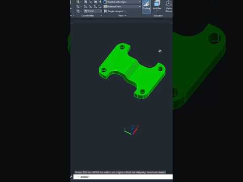
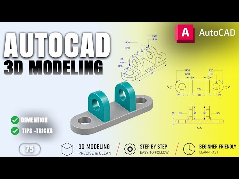
Mastering Mechanical Design: A Step-by-Step Guide to 3D CAD Modeling for Mounting Brackets

In the rapidly evolving world of mechanical engineering, the ability to transform a conceptual 2D sketch into a functional, three-dimensional model is a critical skill. Whether you are a student or a seasoned professional, mastering 3D CAD software is essential for staying competitive in the design industry. In this guide, we will explore the foundational techniques used to create a mechanical mounting bracket, a common component found in various industrial applications.

Understanding the Component: The Mounting Bracket

The project focuses on a 3D mechanical mounting bracket, a vital piece of hardware used to secure components in place. The design features a long, rounded rectangular base plate, which provides stability and a solid surface for attachment. This specific model serves as an excellent practice piece because it combines basic geometric shapes with precise technical requirements.

By focusing on the base plate first, designers can learn how to manage fillets (rounded corners) and ensure that the proportions are accurate before moving on to more complex features. Precision is the cornerstone of mechanical design, and practicing with these foundational shapes builds the necessary muscle memory for larger projects.

The 3D CAD Modeling Workflow

To create this bracket, the modeling process typically begins with a 2D profile. Using 3D CAD tools, the designer draws the footprint of the bracket, ensuring that the dimensions for the length and width are exact. Once the 2D sketch is finalized, the "Extrude" command is used to give the bracket its thickness.

Key steps in this workflow include: 1. Sketching the Base: Creating the rectangular profile with rounded ends. 2. Adding Mounting Holes: Positioning two mounting holes accurately to ensure the bracket can be bolted to a surface. 3. Applying 3D Transforms: Using subtraction or union tools to finalize the mechanical structure.

Why Practice Matters

Mechanical practice work, such as modeling this mounting bracket, is about more than just learning software buttons; it is about understanding spatial relationships and manufacturing constraints. Utilizing 3D CAD allows you to visualize potential interference issues and material thickness before a single part is ever manufactured.

As you continue your journey in AutoCAD and 3D modeling, remember that consistency is key. Exercises like these prepare you for complex assemblies, helping you bridge the gap between a simple idea and a professional-grade mechanical component.

Continue Reading | ความคิดเห็น

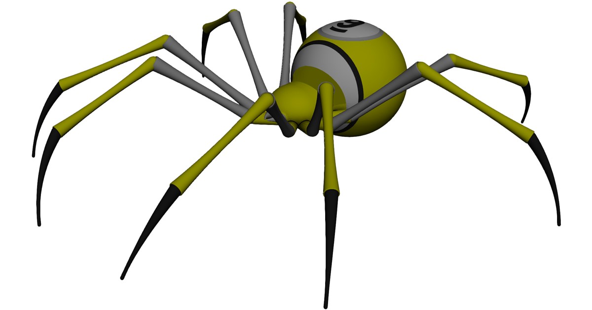
Free 9-Ball Spider CAD Model Download | Multi-Format 3D Asset

Preview Image

Overview

Enhance your sports equipment design, animation, or mechanical engineering projects with this high-precision 9-Ball Spider CAD Model. Commonly used in pool and billiards as a bridge accessory for hard-to-reach shots, this model features accurate geometric detailing suitable for product design, digital rendering, and CNC manufacturing workflows.

Key Features & Specifications

  • Broad Software Compatibility: Ready to import into AutoCAD, SolidWorks, Autodesk Inventor, PTC Creo, CATIA, Siemens NX, Pro/ENGINEER, and ACIS-supported packages.
  • Design Ready: Optimized for easy integration into larger assembly models or standalone render setups.
  • Multi-Format Availability: Compatible with primary neutral and native CAD formats for seamless cross-platform usage.

Applications

Whether you are designing custom gaming hardware, creating realistic 3D sports visualizations, or testing mechanical simulations, this CAD asset offers a reliable digital foundation.


Continue Reading | ความคิดเห็น

Master AutoCAD: A Step-by-Step Guide to 3D CAD Modeling

Transitioning from traditional 2D drafting to the dynamic world of digital design can seem intimidating, but learning 3D CAD is one of the most rewarding skills for students, engineers, and designers alike. Whether you are completing a practical class assignment or building a professional design portfolio, creating three-dimensional figures is an essential step in modern CAD mastery.

In this guide, we will break down the core process of transforming simple concepts into fully realized solid models using AutoCAD.

Setting Up Your 3D Workspace

Before creating any object, you need to prepare your design environment. Switch your workspace from the standard "2D Drafting & Annotation" mode to "3D Modeling." This change gives you direct access to powerful modeling tools, such as solid primitives, extrusion features, and Boolean commands.

When working in a 3D CAD environment, dynamic navigation is critical. Learn to use the ViewCube and Navigation Bar to orbit around your workspace smoothly. Viewing your project from multiple angles ensures accurate alignment along the X, Y, and Z axes.

Key Steps to Construct a 3D Figure

Building a complex 3D figure typically follows a simple, structured workflow:

  1. Draw the 2D Outline: Start by creating a accurate 2D base profile using closed polylines. A clean 2D sketch forms the foundation of any solid model.
  2. Extrude or Presspull: Convert your flat sketch into a solid shape by giving it height. Use the Extrude or Presspull tool to extend the geometry along the Z-axis.
  3. Refine with Boolean Operations: Combine different shapes using the Union tool, or create cutouts, holes, and slots using the Subtract command.

Tips for an Efficient Workflow

To keep your design process smooth and organized, implement these quick tips: - Organize with Layers: Keep your original 2D construction lines, solid models, and annotations on separate layers. - Toggle Visual Styles: Switch between "2D Wireframe" for precise snapping and "Shaded with Edges" to preview your final 3D figure. - Practice with Hands-On Tasks: The fastest way to learn is by following practical tutorials and recreating real-world mechanical parts or geometric shapes.

By mastering these fundamental techniques, you will be well on your way to creating accurate, professional-grade models in 3D CAD. Open your software, try out these steps, and bring your designs to life today!

Continue Reading | ความคิดเห็น

Star Wars Droideka 3D Model: High-Detail Asset for Blender, Unreal & 3ds Max

Preview Image

Enhance your sci-fi renderings, game development, and animation projects with this iconic Star Wars Droideka (Destroyer Droid) 3D Model. Designed with high-precision geometry, this versatile 3D asset captures the distinct mechanical detailing of the Trade Federation's formidable combat droid, ready for integration into major 3D creation suites.

Key Features & Technical Specs:

  • Multi-Software Compatibility: Fully adaptable for 3ds Max, Maya, Blender, Cinema 4D, Unreal Engine, and Unity pipelines.
  • Detailed Mechanical Geometry: Accurately rendered hard-surface components ideal for close-up shots and high-resolution visual effects (VFX).
  • Game & VR/AR Ready: Optimized structure suitable for real-time engines, virtual reality applications, and interactive experiences.
  • Flexible Pipeline Use: Easily riggable and ready for texturing, lighting, and animation setups.

Recommended Applications:

Whether you are producing fan-made cinematic trailers, building immersive sci-fi environments, or studying complex mechanical 3D modeling techniques, this Droideka model serves as a robust asset for your digital content creation (DCC) workflow.


Continue Reading | ความคิดเห็น

Unleashing Innovation: Inside the Modern 3D CAD Lab

Tuesday, September 8, 2026

In today’s fast-paced technological landscape, engineering education and industrial design are undergoing a massive transformation. At the heart of this revolution is the state-of-the-art 3D CAD lab, a dedicated workspace where students, researchers, and engineers turn complex virtual ideas into tangible reality. Computer-Aided Design has evolved far beyond basic 2D drafting, becoming the cornerstone of modern manufacturing, robotics, and structural engineering.

Transforming Virtual Designs into Physical Prototypes

A modern design facility serves as a vital bridge between theoretical engineering concepts and practical applications. Inside a fully equipped 3D CAD lab, creators learn to manipulate complex three-dimensional geometries, run real-time stress simulations, and optimize mechanical components long before any physical materials are used.

When paired with additive manufacturing technologies like 3D printing, the capabilities of modern design tools expand exponentially. Engineers can conceptualize a part in the digital workspace, refine its dimensions, and send it directly to a 3D printer. This seamless integration allows for rapid prototyping—reducing development cycles from months to just hours and encouraging a mindset of experimentation and continuous improvement.

Key Advantages of Hands-On Design Facilities

Industry standards now require modern engineering graduates to possess strong practical expertise in digital design software. Working directly within a dedicated lab environment provides several distinct benefits:

  • Enhanced Spatial Visualization: Designers can view, rotate, and analyze complex assemblies from every angle.
  • Early Defect Detection: Virtual stress testing helps identify structural weaknesses and interference issues prior to production.
  • Resource Conservation: Testing performance digitally drastically reduces material waste and prototyping costs.

Shaping the Future of Digital Manufacturing

As modern manufacturing shifts toward automation and digital twin integration, mastery of digital modeling tools is essential. Modern 3D CAD software empowers multidisciplinary teams—from mechanical to electrical engineers—to collaborate on a single unified platform.

By investing time in advanced design labs, aspiring engineers gain the hands-on expertise required to solve real-world industrial challenges. These facilities do not just teach software; they cultivate the problem-solving mindset necessary to design the technological advancements of tomorrow.

Continue Reading | ความคิดเห็น

Industrial Robot Arm 3D Model: High-Detail Asset for CAD, Blender & Game Engines

Preview Image

High-Detail Industrial Robot Arm 3D Model

Enhance your industrial visualizations, robotics simulations, and sci-fi game environments with this versatile Robot Arm 3D Model. Designed for high compatibility and performance, this mechanical asset is perfect for engineers, 3D animators, and game developers alike.

Key Features & Technical Compatibility:

  • Multi-Platform Support: Fully compatible with leading 3D software including 3ds Max, Maya, Blender, and Cinema 4D.
  • Real-Time & VR Ready: Prepped for seamless import into Unreal Engine and Unity for game development and interactive VR simulations.
  • Mechanical Design: Detailed joint articulation and realistic structural components suited for engineering visualization.

Download this essential robotic asset to streamline your workflow and elevate your rendering and CAD projects.


Continue Reading | ความคิดเห็น

How to Use the AutoCAD INTERSECT Command for Efficient 3D CAD Modeling

Creating complex shapes and geometry in modern design software doesn't have to be a slow, tedious process. If you are working on a 3D CAD project in AutoCAD, mastering Boolean operations can drastically speed up your modeling workflow. One of the most powerful yet straightforward tools in this set is the INTERSECT command.

What is the INTERSECT Command in AutoCAD?

The INTERSECT command allows you to combine two or more overlapping 3D solids or 2D regions to create a brand-new object. Instead of manually trimming lines or calculating complex angles, AutoCAD evaluates the overlapping volume of your selected shapes, deletes the surrounding non-overlapping portions, and leaves you with the exact shared geometric core.

Step-by-Step Guide to Using the INTERSECT Command

Using this feature is quick and intuitive. Follow these simple steps to isolate common areas easily:

  1. Create Overlapping Objects: Draw two or more overlapping 3D solids (such as a cylinder passing through a cube) or 2D regions on your workspace.
  2. Activate the Command: Type INTERSECT (or the keyboard shortcut IN) into the command line and press Enter.
  3. Select Your Objects: Click on all the overlapping objects you want to calculate the shared area for.
  4. Finalize the Operation: Press Enter. AutoCAD instantly removes the surrounding geometry, keeping only the intersecting shape.

Why Include INTERSECT in Your Design Workflow?

Boolean tools like Union, Subtract, and Intersect form the foundation of professional 3D CAD modeling. Integrating the INTERSECT tool into your daily drafting routine offers several key advantages:

  • Time Efficiency: Generate intricate, custom shapes in seconds without having to rebuild complex boundaries from scratch.
  • High Precision: Eliminate human error when finding the exact overlapping boundaries of curved or angled solids.
  • Design Versatility: Ideal for creating mechanical parts, custom architectural joints, and specialized industrial components.

Conclusion

Understanding how to extract common areas using the INTERSECT command is an essential skill for anyone looking to optimize their 3D CAD productivity. Try experimenting with different overlapping shapes in AutoCAD today to see how much time this practical feature can save you on your next design project!

Continue Reading | ความคิดเห็น

Star Wars R2-D2 3D Model: Download for Blender, Maya & Game Engines

Preview Image

Bring the iconic astromech droid to life in your creative projects with this detailed Star Wars R2-D2 3D Model. Precision-modeled for versatility, this asset is optimized for seamless integration across industry-standard 3D software and real-time rendering engines.

Key Features & Compatibility:

  • Multi-Platform Support: Fully compatible with 3ds Max, Maya, Blender, Cinema 4D, and major CAD/3D suites.
  • Real-Time & VR Ready: Optimized geometry suitable for deployment in Unreal Engine, Unity, and interactive VR/AR environments.
  • Detailed Geometry: Faithfully recreates R2-D2's classic dome, mechanical paneling, and proportions for high-quality visual renders.

Ideal Use Cases:

Perfect for VFX animation, sci-fi game development, virtual production, 3D visualization, and digital asset collection.


Continue Reading | ความคิดเห็น

Mastering 3D CAD: Real Student Feedback on Learning Civil 3D with Dr. Abrar Khalak

In the rapidly evolving world of civil engineering and infrastructure design, staying ahead of technical trends is essential. Mastering industry-standard software not only boosts design productivity but also opens up exciting career opportunities. Among these essential technical skills, proficiency in 3D CAD modeling through specialized programs like Autodesk Civil 3D stands out as a game-changer for aspiring and practicing engineers alike.

Why Learn Civil 3D with Dr. Abrar Khalak?

Learning complex engineering software requires more than just basic tutorials; it demands expert mentorship and a structured curriculum. Dr. Abrar Khalak has earned a stellar reputation for delivering comprehensive, practical, and highly engaging Civil 3D training. His teaching approach focuses on real-world practical application, effectively bridging the gap between theoretical engineering concepts and actual project execution.

Through hands-on exercises, students learn how to navigate land development, road design, surveying, and site planning using advanced 3D CAD workflows.

Student Reviews: Key Takeaways and Results

Students who recently completed the Civil 3D training under Dr. Abrar Khalak’s guidance have shared overwhelmingly positive reviews. Here are some of the key highlights expressed in their feedback:

  • Practical Project Experience: Learners appreciated working directly with realistic engineering datasets, gaining the confidence to tackle actual industry challenges.
  • Simplified Learning Curve: Complex technical topics—such as surface creation, corridor design, grading, and pipe networks—were broken down into clear, easy-to-digest lessons.
  • Improved Design Efficiency: Many students noted significant improvements in their workflow speed and accuracy, preparing them for professional engineering roles.

Take Your Engineering Career to the Next Level

Whether you are a university student, a recent graduate, or an experienced professional seeking to upgrade your software expertise, investing in comprehensive 3D CAD education is one of the smartest career moves you can make. Dr. Abrar Khalak’s Civil 3D course equips you with the practical skills and confidence needed to succeed in modern civil design.

Continue Reading | ความคิดเห็น

Star Wars C-3PO Droid 3D Model | Multi-Format CAD Resource

Preview Image

Bring the iconic protocol droid to life in your next digital project with the Star Wars C-3PO Robot 3D Model. Designed for high compatibility across leading software suites, this detailed 3D asset is tailored for game developers, VFX artists, and 3D visualization professionals.

Features & Compatibility:

  • Software Support: Fully adaptable for 3ds Max, Maya, Blender, Cinema 4D, Unreal Engine, and Unity.
  • Versatile Use Cases: Perfect for virtual reality (VR), augmented reality (AR), cinematic animation, and sci-fi environment renderings.
  • Accurate Detailing: Captures the distinct metallic finish and intricate structural elements of the classic Star Wars character.

Enhance your sci-fi pipeline today by downloading this optimized C-3PO 3D asset for your rendering and real-time engines.


Continue Reading | ความคิดเห็น

3D Scanning Explained: Bridging the Gap Between Physical Parts and 3D CAD

In today's fast-paced engineering landscape, capturing the exact geometry of a physical object is essential for redesign, quality control, and reverse engineering. Whether you need to reproduce a legacy mechanical component without original blueprints or analyze a complex prototype, 3D scanning provides the ultimate solution. This technology seamlessly bridges the gap between the physical world and digital design, transforming tangible parts into workable 3D CAD data.

How 3D Scanning Digitizes Physical Parts

3D scanning works by capturing the surface measurements of a physical object using lasers, structured light, or photogrammetry. As the scanner projects light or laser lines onto the component, advanced sensors calculate millions of spatial data points in seconds.

This process generates a dense "point cloud," which is then connected to form a polygon mesh—a high-fidelity digital representation of the physical object's exterior geometry. From intricate automotive components to custom medical devices, 3D scanners capture complex organic curves and fine details that traditional measuring tools like calipers simply cannot match.

Transforming Raw Scans into Parametric Models

While a raw 3D scan provides an accurate visual surface mesh, it isn't immediately ready for parametric manufacturing or mechanical modification. To unlock its full potential, engineers transfer the mesh data into professional 3D CAD software for reverse engineering.

In this stage, the scanned mesh serves as a precise digital blueprint. Designers use specialized modeling tools within their 3D CAD environment to extract geometric features, align mechanical axes, and rebuild clean, editable solid geometry. This allows engineering teams to modify dimensions, add mounting features, or optimize the design for modern production methods such as 3D printing and CNC machining.

Why Digital Integration Matters for Manufacturing

Connecting physical hardware with digital workflows offers powerful competitive advantages: - Accelerated Product Development: Drastically reduce the time required to measure, model, and iterate existing components. - Legacy Part Preservation: Effortlessly archive and re-manufacture obsolete parts that lack original technical drawings. - Enhanced Quality Inspection: Overlay scanned physical parts against their original digital blueprints to instantly detect manufacturing deviations and tolerances.

By converting physical components into versatile digital assets, modern scanning technology combined with CAD software empowers engineers to innovate faster, improve accuracy, and streamline the entire product lifecycle.

Continue Reading | ความคิดเห็น

Popular Posts Today

 
Support : 3Dcadbrowser | Grabcad | 3Dcontentcentral | D | E | F | G
Copyright © 2028. Engineering 3DCad Appication - All Rights Reserved