Cad 3D Category

Showing posts with label AutoCAD Tutorial. Show all posts

Master Multiline Text: A Step-by-Step Guide for AutoCAD 3D Users

Sunday, November 1, 2026
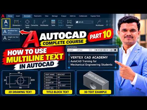
Clear communication is essential when creating precise engineering drawings and architectural plans. Whether you are drafting basic 2D floor plans or working on complex AutoCAD 3D models, adding detailed annotations, dimensions, and explanatory notes ensures your designs are correctly understood. One of the most powerful annotation tools available in AutoCAD is the Multiline Text (MTEXT) feature.

In this quick guide, you will learn how to efficiently use Multiline Text to streamline your documentation workflow.

Why Choose Multiline Text Over Single Line Text?

Unlike Single Line Text, Multiline Text (MTEXT) gives you complete control over paragraph formatting, word wrapping, alignment, and styling. Key advantages include:

  • Advanced Formatting: Adjust font styles, text height, colors, and line spacing within a single text block.
  • Bullets and Lists: Easily create numbered or bulleted specifications directly on your technical drawings.
  • Columns and Margins: Organize extensive notes into clean, readable multi-column layouts without manual line breaks.

Step-by-Step: How to Use Multiline Text in AutoCAD

Using the MTEXT command is straightforward and fits seamlessly into any workflow, whether you are focusing on traditional drafting or detailed AutoCAD 3D projects.

  1. Activate the Command: Type MTEXT or the shortcut MT into the command line and press Enter. Alternatively, select Multiline Text from the Annotation panel on the Home ribbon tab.
  2. Specify the Boundary: Click once in your workspace to set the first corner of your text frame, then drag and click again to set the opposite corner. This bounding box defines the width of your text paragraph.
  3. Enter Your Content: The Text Editor contextual tab will automatically open. Type your technical notes, descriptions, or instructions inside the frame.
  4. Format the Appearance: Highlight any portion of your text to change its font style, height, justification, or insert special symbols (such as degree, diameter, or plus/minus symbols).
  5. Close and Save: Click Close Text Editor on the ribbon or click anywhere outside the text boundary box to apply the changes.

Tips for Better Annotation Management

To maintain consistency across large AutoCAD 3D assemblies or standard floor plans, always utilize defined Text Styles (STYLE command). Additionally, placing your MTEXT on dedicated annotation layers allows you to manage object visibility and plotting properties effortlessly.

Conclusion

Mastering Multiline Text is a fundamental skill for any CAD designer looking to produce clean, professional-grade documentation. Start incorporating MTEXT into your daily routine to save time and elevate the quality of your AutoCAD projects today!

Continue Reading | ความคิดเห็น

Mastering 3D Architecture: A Step-by-Step Guide to Two-Point Perspective in AutoCAD

Thursday, October 8, 2026

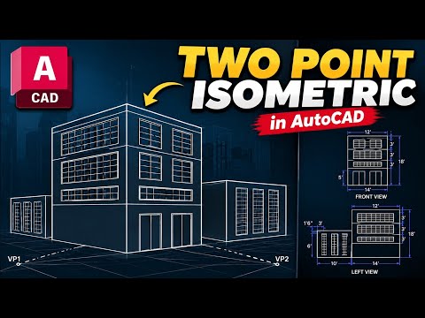
In the world of digital design, the ability to translate a flat concept into a realistic, three-dimensional representation is what sets professional designers apart. When it comes to high-quality 3D architecture, mastering spatial depth is essential for creating compelling visuals that clients can truly understand. One of the most effective ways to achieve this realism in AutoCAD is through the mastery of two-point perspective drawing.

Why Use Two-Point Perspective?

While isometric drawings are excellent for technical clarity, they often lack the natural feel of real-world vision. Two-point perspective solves this by utilizing two vanishing points on a horizon line, mimicking how the human eye perceives buildings from a corner view. This technique is a cornerstone for anyone looking to excel in 3D architecture and professional urban visualization.

Setting Up Your Workspace

Before you begin drawing, ensure your AutoCAD environment is optimized. Start by defining your horizon line—this represents the viewer's eye level. Next, place two vanishing points on the far left and right ends of this line. Organization is key, so we recommend creating specific layers for "Construction Lines," "Main Building Outline," and "Details" to keep your workspace clean.

The Drawing Process: Step-by-Step

  1. The Leading Edge: Start by drawing a single vertical line. This represents the corner of the building closest to the viewer.
  2. Connecting to Vanishing Points: Draw lines from the top and bottom of your vertical edge toward both the left and right vanishing points. This creates the basic "V" shape of your structure.
  3. Defining Depth: Add two more vertical lines to define where the building ends on either side. These lines should stay within the boundaries of the lines connecting to your vanishing points.
  4. Adding Architectural Details: Once the primary block is complete, use the same vanishing point logic to add windows, doors, and rooflines. Every horizontal line on the left side must point to the left vanishing point, and vice-versa.

Conclusion

Perfecting the two-point perspective technique allows you to create more immersive and professional presentations. Visualizing complex structures requires a solid foundation in 3D architecture principles, and AutoCAD provides all the precision tools necessary to bring these perspectives to life. With practice, you will be able to transform simple floor plans into dynamic, three-dimensional masterpieces.

Continue Reading | ความคิดเห็น

Mastering AutoCAD: A Beginner’s Guide to Essential CAD tools and Commands

Thursday, September 17, 2026

Have you ever looked at a complex architectural blueprint and wondered how such precision is achieved? AutoCAD is the industry-leading software for 2D and 3D design, serving as the backbone for architects, engineers, and designers worldwide. However, for a complete beginner, the interface can often feel overwhelming. The key to success lies in mastering the fundamental CAD tools that form the basis of every professional drawing.

Getting Started with the AutoCAD Interface

Before diving into complex designs, it is crucial to understand that AutoCAD is a command-driven environment. While you can click icons, the most efficient way to work is by using keyboard shortcuts. This approach not only speeds up your workflow but also allows you to focus more on the creative aspect of your project. As you familiarize yourself with the workspace, you will notice that most high-level drafting relies on a handful of core functions.

Essential Drawing Commands

To start your journey, you must master the basic drawing commands. The "Line" (L) command is perhaps the most used feature, allowing you to create straight segments between two points. Similarly, the "Circle" (C) and "Rectangle" (REC) commands allow for the quick generation of geometric shapes. By learning how to input specific coordinates and dimensions into these CAD tools, you ensure that your designs are accurate to the millimeter.

Modifying and Refining Your Designs

Drawing a line is only the beginning; the real power of AutoCAD lies in its modification capabilities. Tools such as "Trim" (TR) allow you to cut overlapping lines, while "Offset" (O) is indispensable for creating parallel lines—perfect for defining wall thicknesses in floor plans. Additionally, the "Mirror" (MI) command can save hours of work by reflecting symmetrical objects across an axis.

Conclusion: Practice Makes Perfect

Mastering AutoCAD is a journey of consistency. By focusing on these primary CAD tools and practicing them daily, you will transform from a novice into a confident drafter. Remember, every complex architectural marvel started with a simple line. Start small, stay curious, and keep practicing your commands to unlock the full potential of digital drafting.

Continue Reading | ความคิดเห็น

Mastering 3D CAD: How to Model a Mechanical Mounting Bracket in AutoCAD

Friday, September 11, 2026

In the evolving world of mechanical engineering, the ability to transform a 2D concept into a functional 3D model is an essential skill. One of the best ways to sharpen these skills is through practical, hands-on exercises that replicate real-world components. In this guide, we explore the process of creating a mechanical mounting bracket, a fundamental tool in the world of 3D CAD.

Starting with the Foundation: The Base Plate

Every great mechanical model begins with a solid foundation. For this mounting bracket project, we start by constructing a rectangular base plate. In AutoCAD, this involves using primitive shapes or extruding a 2D rectangle to a specific thickness. By assigning a distinct color—such as a vibrant red—designers can easily differentiate between various components within a complex assembly. This level of visual clarity is one of the many advantages of using professional 3D CAD software for mechanical practice.

Precision Engineering and Mounting Holes

A mounting bracket is only as functional as its connectivity. The next critical step in the modeling process is the addition of four precise mounting holes located at the corners of the base. This requires careful measurement and the use of the "Subtract" command to create clean, accurate voids. This stage of the project emphasizes the importance of geometric constraints and precision, ensuring that the digital part would theoretically fit perfectly into a real-world mechanical assembly.

Why Practice Work is Essential

Whether you are a student or an aspiring engineer, consistent practice is the key to proficiency. Transitioning from basic shapes to complex mechanical parts helps users understand the workspace, the Z-axis, and the various shortcuts that speed up the design process. Utilizing 3D CAD for these practice sessions allows you to experiment with different materials, lighting, and viewing angles before moving on to more intricate industrial designs.

Conclusion

Modeling a mechanical mounting bracket is more than just a basic exercise; it is a stepping stone to mastering industrial design. By following these fundamental principles in AutoCAD, you can build a strong portfolio of mechanical parts and gain the confidence needed to tackle large-scale engineering projects. Keep practicing, keep designing, and unlock the full potential of your technical creativity!

Continue Reading | ความคิดเห็น

Step-by-Step 3D CAD Tutorial: Designing a Mechanical Mounting Bracket in AutoCAD

Thursday, August 20, 2026

Are you looking to level up your mechanical engineering skills or master computer-aided design? Transitioning from 2D drafting to solid modeling is one of the most rewarding steps in modern engineering. By leveraging power-packed 3D CAD software like AutoCAD, you can transform flat conceptual sketches into highly accurate, detailed mechanical components ready for manufacturing.

In this practical guide, we will explore the fundamental steps and techniques required to model a detailed mechanical mounting bracket from scratch.

Essential Tools for Mechanical Solid Modeling

Creating robust mechanical parts relies on mastering a few core solid modeling operations. When working on a mounting bracket or similar mechanical component, you will frequently utilize:

  • Extrude: Convert basic 2D closed polylines into 3D solid shapes by adding height or depth.
  • Subtract: Hollow out sections, create bolt holes, or carve keyways by subtracting one solid shape from another.
  • Union & Intersect: Combine multiple distinct solids into a single unified object or extract overlapping geometries.

Understanding how these boolean operations interact allows you to build sophisticated components out of simple geometric primitives.

Designing a Mechanical Mounting Bracket Step-by-Step

To build a realistic mechanical mounting bracket, precision is key. Follow these practical stages during your modeling workflow:

  1. Draft the Base Profile: Start in a 2D view by sketching the base plate and side support ribs with exact dimensions.
  2. Convert to 3D: Apply the Extrude tool to give thickness to your base and vertical mounting walls.
  3. Add Fastener Holes: Draw 2D circles at the designated mounting points, extrude them through the solid body, and apply the Subtract command to generate precise screw clearance holes.
  4. Refine and Fillet: Smooth sharp outer edges using the Fillet Edge command to reduce stress concentrations in your 3D CAD model.

Tips for an Efficient Modeling Workflow

Mastering 3D CAD modeling requires both technical knowledge and disciplined habits. Always ensure your 2D sketches are properly closed before extruding to avoid mesh or surface errors. Additionally, utilize custom User Coordinate Systems (UCS) when placing features on angled surfaces, and regularly switch visual styles (from Wireframe to Conceptual or X-Ray) to inspect your model's internal geometry.

With consistent practice on real-world projects like mounting brackets, you will quickly develop the speed and confidence needed for professional mechanical design.

3D CAD
Continue Reading | ความคิดเห็น

Popular Posts Today

 
Support : 3Dcadbrowser | Grabcad | 3Dcontentcentral | D | E | F | G
Copyright © 2028. Engineering 3DCad Appication - All Rights Reserved