Cad 3D Category

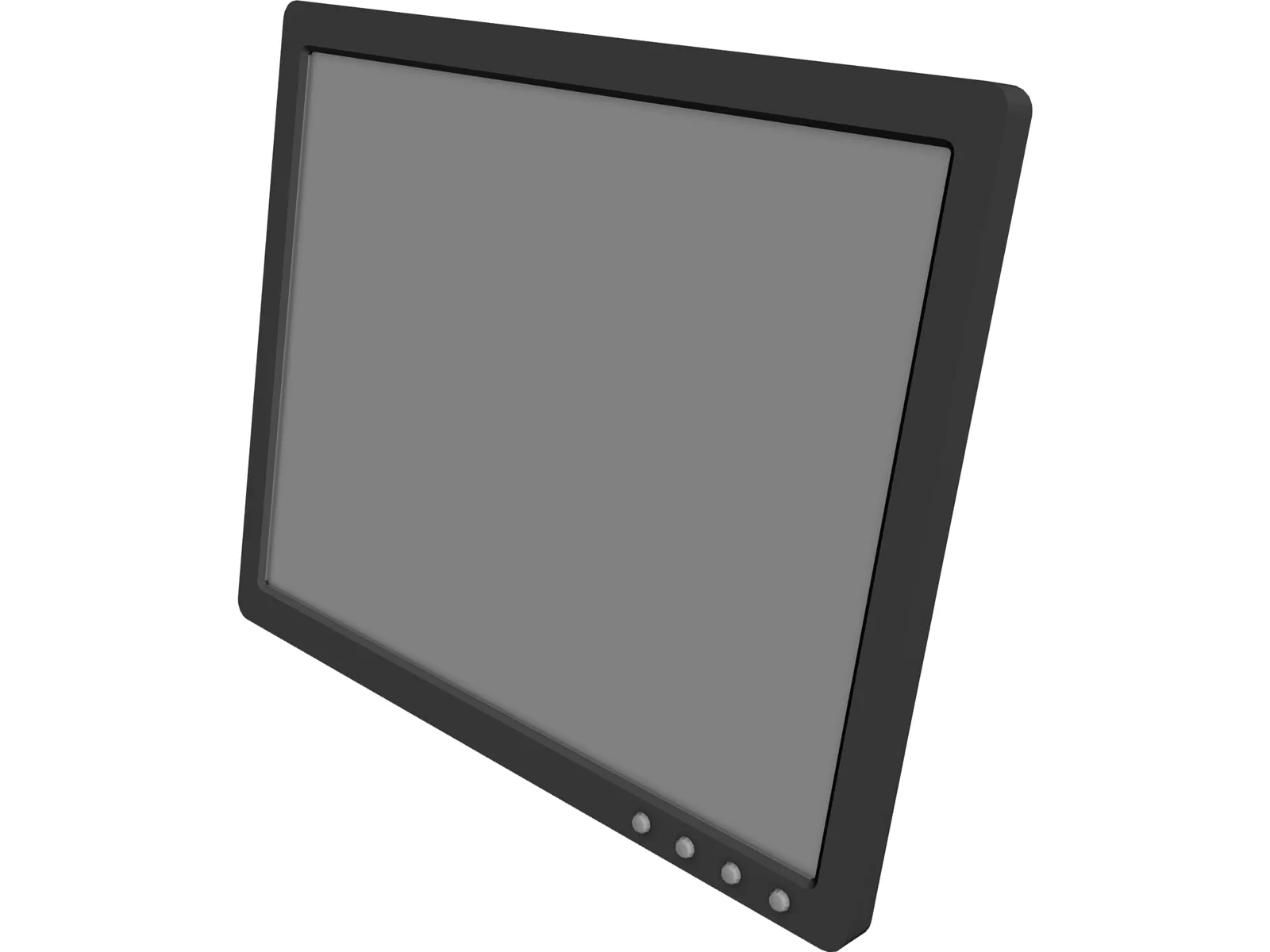
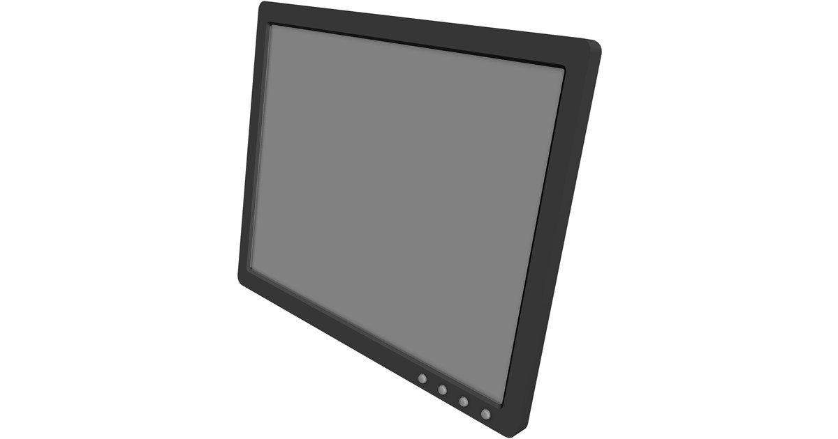
19-Inch LCD Monitor Free 3D CAD Model (SolidWorks, AutoCAD, CATIA)

Thursday, September 3, 2026

Preview ImagePreview ImagePreview Image

Enhance your engineering, office layout, or product design projects with this detailed Free 19-inch LCD Monitor 3D CAD Model. Ideal for workstation visualization, hardware mounting design, and industrial layout planning.

Key Features:

  • Accurate Dimensions: Realistic 19-inch aspect ratio and standard bezel details for precise fitting.
  • Multi-CAD Compatibility: Seamlessly import into any major CAD software suite.
  • Versatile Use: Suitable for ergonomics testing, desk setup designs, and control room simulations.

Supported Software Formats:

  • SolidWorks, AutoCAD, Autodesk Inventor
  • PTC Creo / Pro-E, Siemens NX, CATIA
  • Universal formats (STEP, IGES, ACIS)

Continue Reading | ความคิดเห็น

Mastering Precision: How to Separate Polyline Segments in 3D CAD

Wednesday, September 2, 2026

In the world of digital drafting and modeling, efficiency is just as important as accuracy. One of the most common entities you will encounter when working with professional design software is the polyline—a connected sequence of segments created as a single object. While polylines are incredibly useful for maintaining continuity in a design, there are many instances where you need to isolate or separate a single line from the group.

Whether you are cleaning up a floor plan or preparing a complex geometric shape for a 3D CAD project, knowing how to manipulate these lines is a fundamental skill. In this guide, we will explore the most effective ways to separate polyline segments without losing your design’s integrity.

Why Separate Polylines?

When working within a 3D CAD environment, you might find that a single polyline is preventing you from applying specific offsets, extrusions, or fillets to just one part of your model. By breaking the polyline into individual segments, you gain granular control over your geometry. This allows for more detailed editing, such as changing the layer, color, or thickness of just one specific section of what was previously a unified shape.

The "Explode" vs. "Break" Method

There are two primary ways to handle this task depending on your specific needs:

  1. The Explode Command: If you need to turn the entire polyline into individual, independent lines, the "EXPLODE" command is your quickest option. Simply select the polyline, type EXPLODE (or X), and press enter. Every segment will now be its own entity.
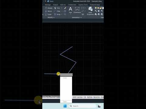
  2. The Edit Polyline (PEDIT) Method: If you only want to remove or disconnect one specific segment while keeping the rest of the polyline intact, the PEDIT command is superior. Within this tool, you can use the "Break" option. This allows you to select two points on the polyline to create a gap, effectively separating the segments at a precise location.

Optimizing Your Workflow

Mastering these small but vital techniques significantly speeds up the drafting process. For those specializing in 3D CAD, maintaining a clean workspace by properly managing polylines ensures that your 3D models are built on a solid, error-free 2D foundation.

By understanding how to bridge the gap between unified shapes and individual segments, you can approach complex architectural or engineering tasks with much greater confidence. Start practicing these commands today to take your CAD skills to the next level!

3D CAD
Continue Reading | ความคิดเห็น

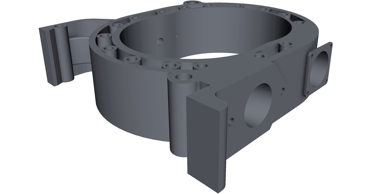
13B PP Engine Rotor Housing 3D CAD Model | Multi-Format Download

Preview ImagePreview ImagePreview Image

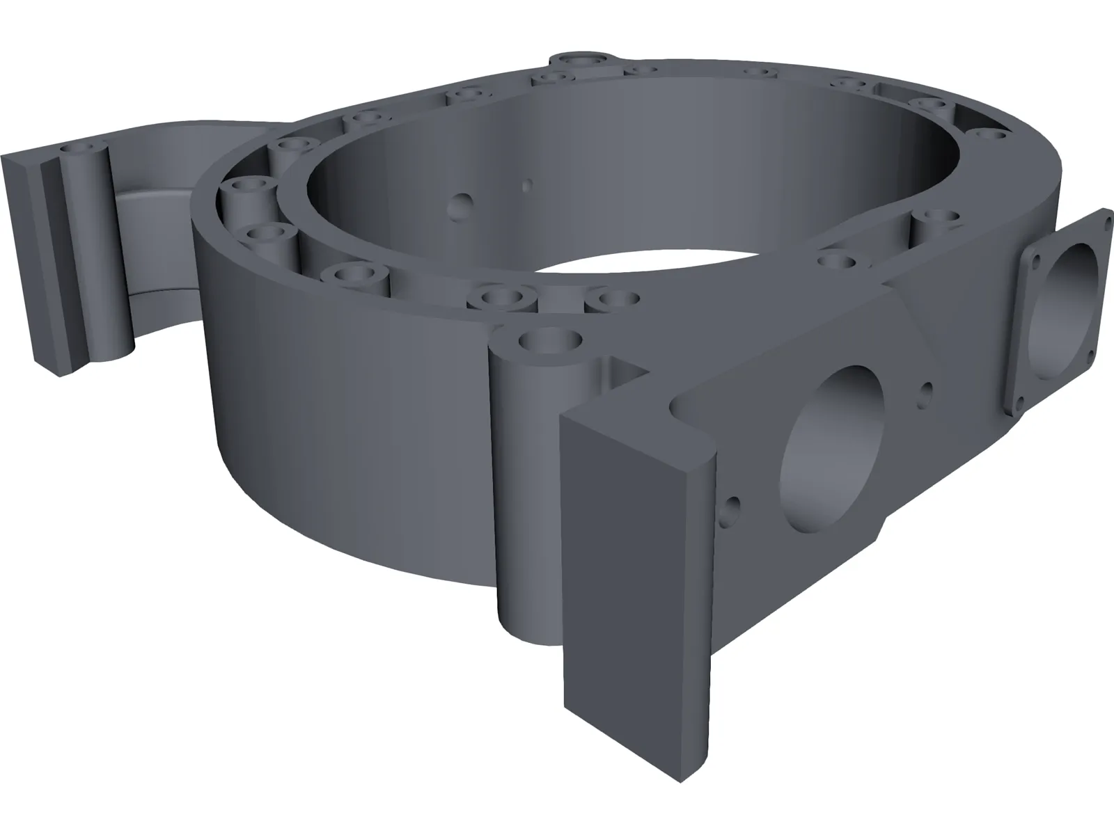
High-Precision 13B Peripheral Port (PP) Engine Rotor Housing 3D CAD Model

Upgrade your automotive engineering and custom engine build projects with this detailed 3D CAD model of the legendary Mazda 13B Peripheral Port (PP) Engine Rotor Housing. Ideal for performance tuning, custom manifold design, fluid dynamics simulation (CFD), and full engine assembly modeling.

Key Features & Highlights:

  • Accurate Geometry: Modeled with precise chamber dimensions, mounting holes, and peripheral porting specs.
  • Multi-Software Support: Compatible with major CAD software including SolidWorks, AutoCAD, Autodesk Inventor, PTC Creo, CATIA, Siemens NX, Pro/ENGINEER, and ACIS format.
  • Engineering Applications: Perfect for reverse engineering, custom intake manufacturing, structural analysis, and 3D rendering.

Download this high-quality 3D model today to streamline your rotary engine engineering workflow!


Continue Reading | ความคิดเห็น

Next-Gen 3D CAD Viewing: How AI Analysis Works Safely in Your Browser

In the rapidly evolving world of modern manufacturing, engineering teams are constantly seeking smarter ways to analyze design files and accelerate production. While the desire to integrate artificial intelligence with engineering data is at an all-time high, many organizations find themselves stuck. The primary barrier? Data security. Uploading proprietary engineering models to external cloud servers creates significant compliance and IP risks.

The Evolution of Browser-Based Design Tools

Traditionally, viewing complex CAD files required heavy software installations and specialized hardware. Today, browser-based tools are revolutionizing this process. A modern 3D CAD viewer allows engineers, managers, and supply chain partners to open, inspect, and interact with complex models instantly without installing bloated desktop applications.

However, the real breakthrough occurs when you combine web accessibility with artificial intelligence—without compromising your proprietary data.

Maximum Privacy: Your STEP Files Never Leave Your PC

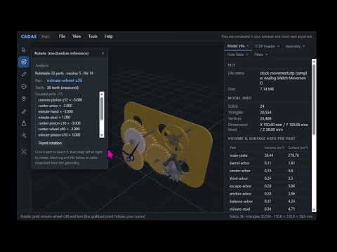
Solutions like CADAS are redefining how teams handle sensitive design files. By processing data locally within your web browser, confidential STEP files never leave your machine. This local-first architecture eliminates the vulnerability of cloud uploads while delivering the high performance expected from traditional desktop software.

By keeping data strictly on your local device, manufacturers can confidently deploy advanced digital tools across global teams without breaching strict non-disclosure agreements or corporate security policies.

Unlocking the Power of Local AI Analysis

Integrating AI into your engineering workflow shouldn't mean sacrificing data control. With browser-native AI analysis, teams can automatically inspect geometry, evaluate manufacturability, and extract critical insights directly from their 3D CAD models in real time.

This seamless integration bridges the gap between raw design data and actionable manufacturing intelligence. Instead of waiting for tedious manual design reviews, engineers can instantly identify potential production bottlenecks directly inside their browser environment.

Transform Your Engineering Workflow

The future of industrial design lies in software that balances cutting-edge intelligence with uncompromised data privacy. By adopting web-based 3D CAD visualization paired with local AI analysis, companies can finally unlock the full potential of their design data—safely, quickly, and efficiently.

3D CAD
Continue Reading | ความคิดเห็น

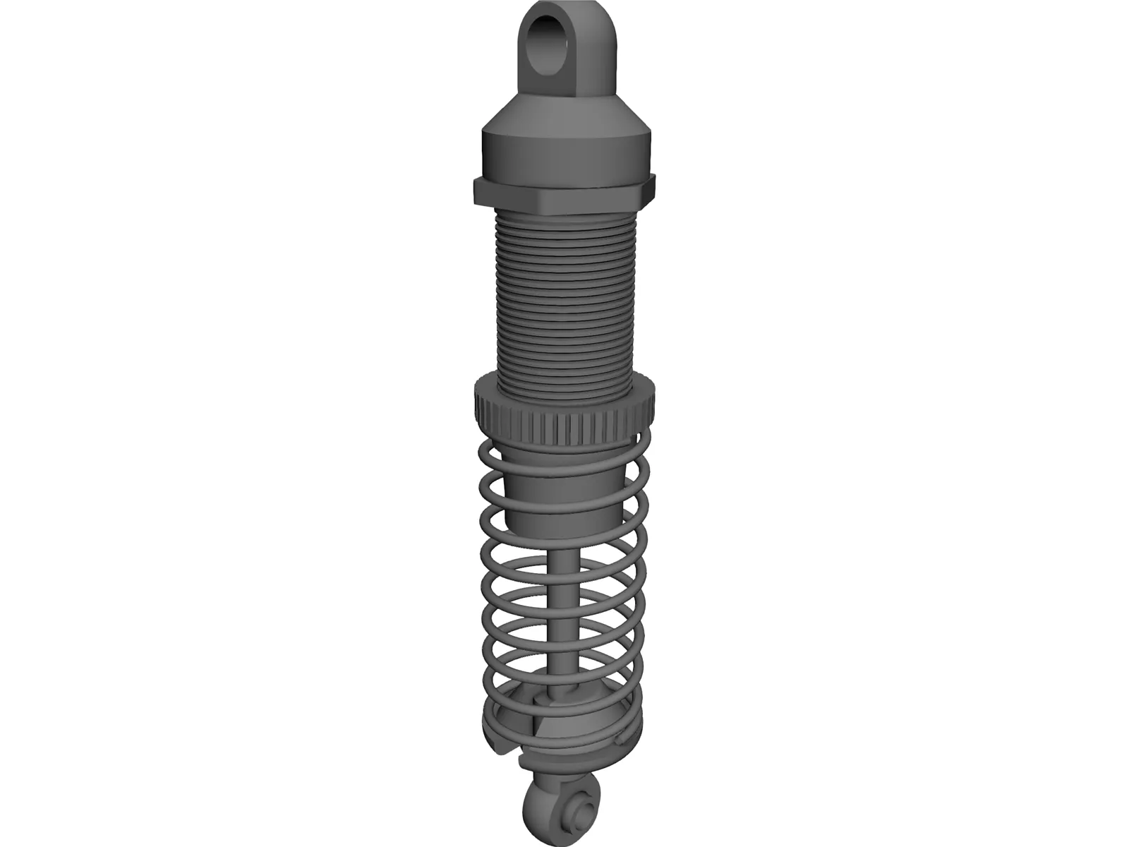
1:10 Scale Off-Road RC Buggy Front Shock CAD Model (Team Associated B4)

Preview ImagePreview ImagePreview Image

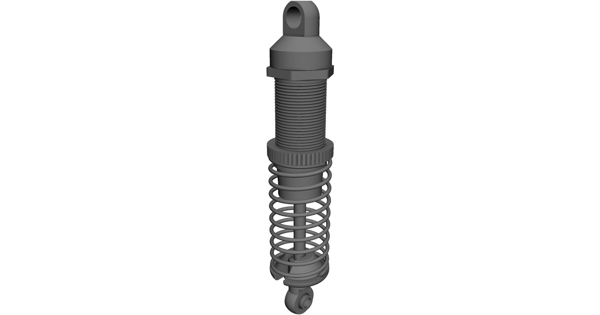
Enhance your mechanical designs and custom RC projects with this highly detailed 1:10 Scale Off-Road RC Buggy Front Shock CAD Model, inspired by the iconic Team Associated B4 platform.

Key Features & Specifications:

  • Accurate Design: Precision-modeled 1:10 scale representation ideal for assembly modeling and fitment testing.
  • Detailed Components: Features realistic geometry for the shock body, damper shaft, spring retainers, and mounting points.
  • Multi-Format Compatibility: Available for seamless import into AutoCAD, SolidWorks, Autodesk Inventor, PTC Creo, Siemens NX, CATIA, Pro/E, ACIS, and standard neutral formats (STEP/IGES).

Use Cases:

Perfect for RC car enthusiasts, suspension dynamics simulation, 3D printing custom replacement parts, or educational mechanical engineering projects.


Continue Reading | ความคิดเห็น

Getting Started with 3D CAD: A Complete Guide to Free CAD 1.1 Installation

In the modern world of engineering and architecture, having access to professional-grade tools shouldn't always come with a high price tag. Whether you are a hobbyist interested in 3D printing or a professional architect, finding a versatile 3D CAD solution is essential for bringing your digital ideas to life. Free CAD 1.1 stands out as a powerful, open-source alternative that caters to a wide range of design needs.

Why Choose Free CAD 1.1?

Free CAD is more than just a simple drawing tool; it is a multi-purpose parametric 3D modeler that excels in various technical fields. From Building Information Modeling (BIM) for architects to Computer-Aided Manufacturing (CAM) for CNC machine enthusiasts, this software provides a comprehensive suite of features.

For those looking to dive into the world of 3D CAD design, Free CAD 1.1 offers a robust platform that supports complex geometry and architectural workflows. Its open-source nature means it is constantly updated by a dedicated community, ensuring that you have access to the latest tools without the heavy subscription fees associated with proprietary software.

Step-by-Step Download and Installation

Getting started with your new design environment is straightforward. To install the software, you should visit the official project website to ensure you are getting a secure and stable build.

  1. Select Your Version: Choose the installer that matches your operating system (Windows, macOS, or Linux).
  2. Run the Installer: Once the download is complete, open the file and follow the on-screen prompts.
  3. Initial Configuration: During the first launch, you can customize your interface based on your specific focus, such as architecture or mechanical design.

The installation process is lightweight and efficient, meaning you can transition from downloading to your first project within minutes.

Versatility in Design and Architecture

One of the biggest advantages of this software is its modularity. If you are focused on mechanical engineering, you can utilize the Part Design workbench to create intricate components. If architecture is your specialty, the BIM tools allow for precise structural planning and 3D visualization. Furthermore, its integration with CNC workflows makes it a favorite for makers who need to bridge the gap between digital design and physical manufacturing.

Conclusion

Mastering 3D CAD is a journey that begins with selecting the right software. Free CAD 1.1 provides the perfect entry point for beginners while remaining powerful enough for advanced users to execute professional-grade projects. By following this guide, you have taken the first step toward professional-level 3D modeling and design. Download it today and start building your vision!

3D CAD
Continue Reading | ความคิดเห็น

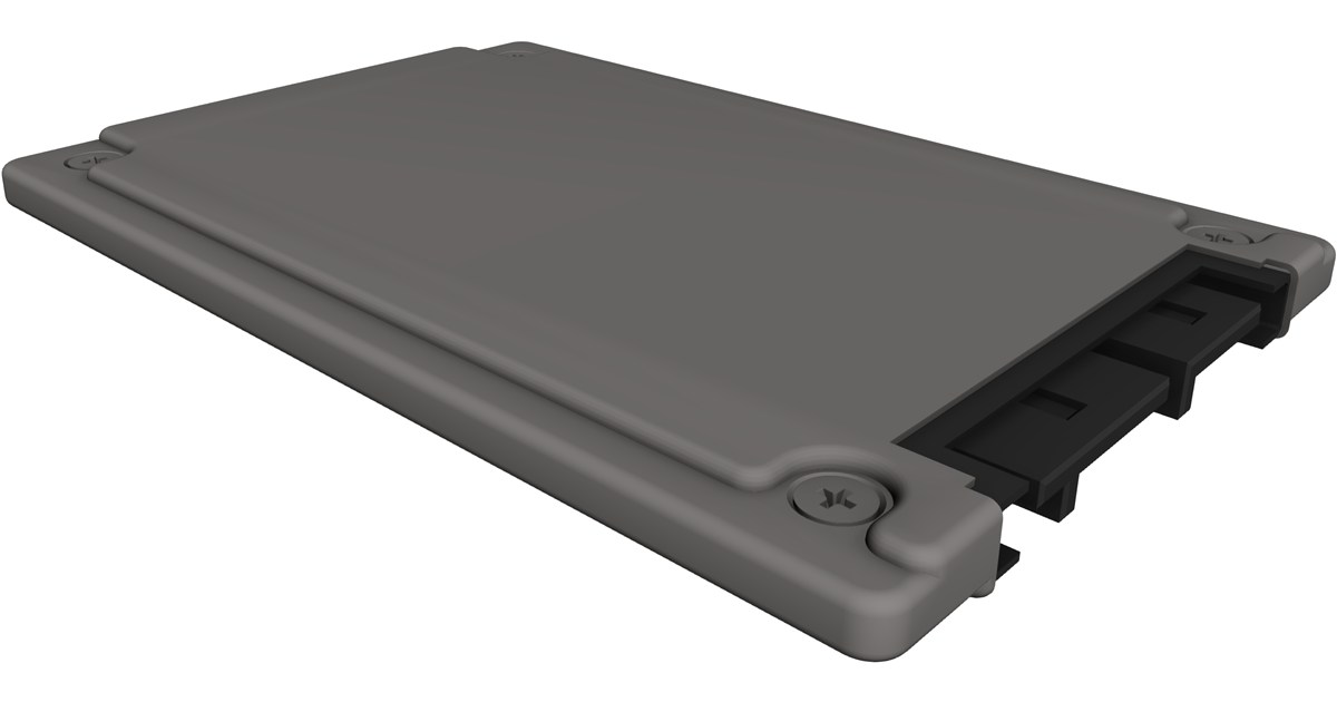
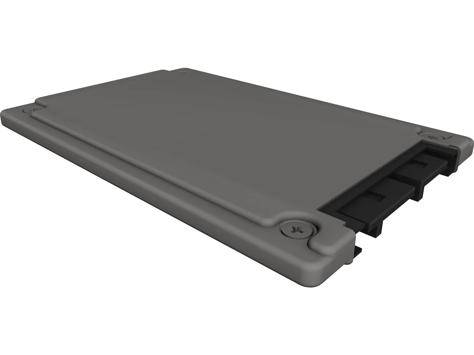
Download 1.8-Inch SATA HDD 3D CAD Model (SolidWorks, CATIA, STEP)

Preview ImagePreview ImagePreview Image

Optimize your hardware design workflow with this highly accurate 1.8-Inch SATA Hard Disk Drive (HDD) 3D CAD Model. Designed for mechanical engineers, electronics packaging designers, and system architects, this model helps streamline component placement and enclosure fit-checks.

Key Features & Specifications:

  • Form Factor: Compact 1.8-inch drive with standard SATA connector interface details.
  • Multi-Format Compatibility: Available for AutoCAD, SolidWorks, Autodesk Inventor, Pro/ENGINEER (PTC Creo), Siemens NX, CATIA, ACIS, and universal STEP/IGES formats.
  • Applications: Ideal for digital prototyping, thermal analysis clearance checks, custom PCB/enclosure design, and technical visualization.

Download this precision CAD assembly to integrate realistic storage hardware into your engineering projects without building models from scratch.


Continue Reading | ความคิดเห็น

Master Interference Checking in AutoCAD: A Guide to Flawless 3D CAD Modeling

When working on complex engineering or architectural designs, precision is everything. A single overlapping component can lead to costly errors during fabrication or construction. If you rely on AutoCAD for your 3D CAD projects, detecting spatial conflicts early is essential to maintaining model accuracy. Fortunately, AutoCAD features a powerful built-in tool specifically designed for clash detection: the INTERFERE command.

What is the INTERFERE Command in AutoCAD?

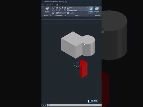
The INTERFERE command allows users to compare sets of 3D solid objects to check if they overlap or occupy the same physical space. Unlike standard Boolean operations such as SUBTRACT or UNION, which permanently alter your geometry, INTERFERE highlights overlapping volumes by generating temporary 3D solids. This lets you inspect and resolve design collisions without modifying your original components.

Step-by-Step: How to Perform an Interference Check

Running an interference check in AutoCAD is straightforward and fast:

  1. Activate the Command: Type INTERFERE into the command line and press Enter.
  2. Select First Object Set: Select the first group of 3D solids you want to check, then press Enter.
  3. Select Second Object Set: Choose the second set of 3D solids to compare against the first (or press Enter again to check for interferences among the first set alone).
  4. Review Results: AutoCAD opens the Interference Checking dialog box and temporarily highlights any overlapping geometry in red.
  5. Manage Clashes: Cycle through each interference point, zoom into specific conflict areas, and choose whether to delete or keep the generated interference solids for reference.

Why Clash Detection Matters for Your Workflow

Integrating regular clash detection into your 3D CAD workflow offers several key advantages:

  • Prevents Manufacturing Errors: Spotting physical overlaps early ensures components fit together seamlessly during actual assembly.
  • Saves Time and Money: Identifying errors during drafting takes seconds, whereas fixing mistakes on the shop floor or construction site is expensive and time-consuming.
  • Improves Model Quality: Clean geometry yields accurate mass property calculations, faster rendering, and seamless exports.

Mastering the INTERFERE command is one of the easiest ways to elevate the quality of your 3D CAD designs. Incorporate this quick check into your routine to ensure your 3D models are accurate, professional, and conflict-free!

3D CAD
Continue Reading | ความคิดเห็น

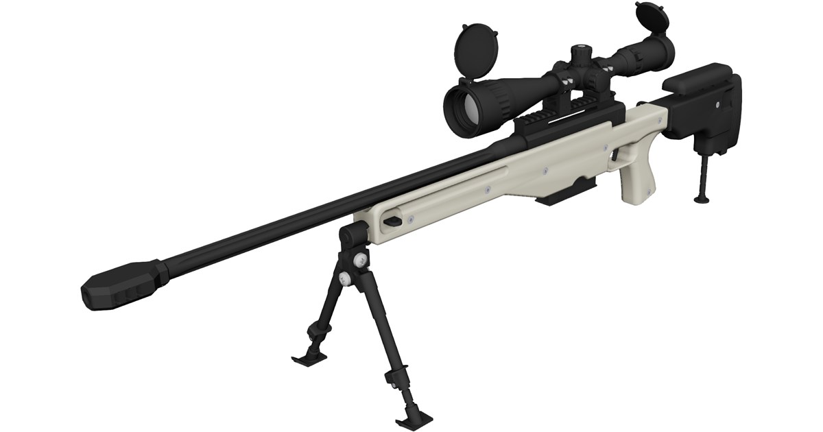
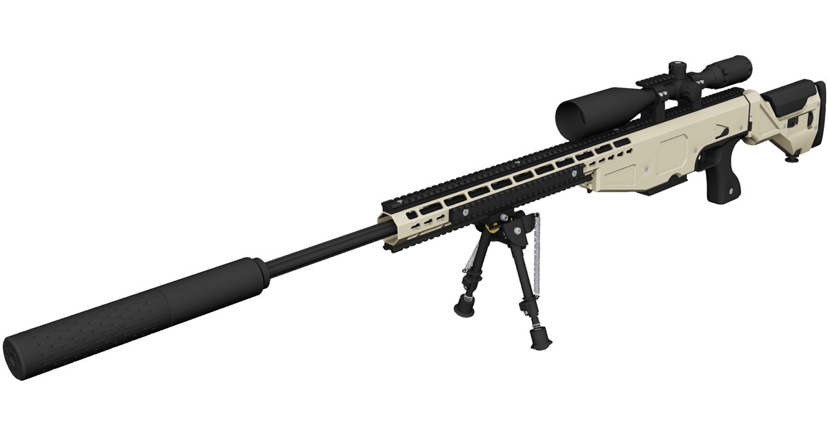
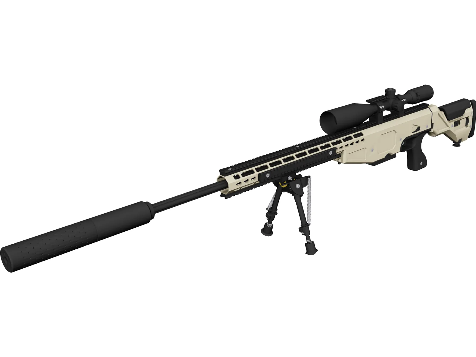
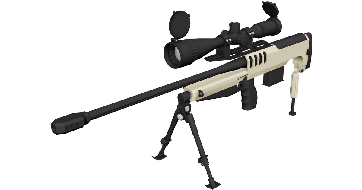
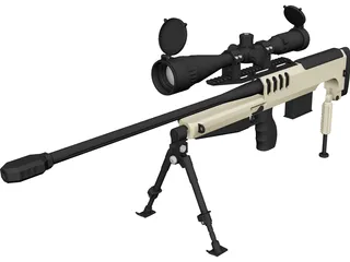
.338 Lapua Magnum Sniper Rifle 3D CAD Model | SolidWorks, CATIA & STEP

Preview ImagePreview ImagePreview Image

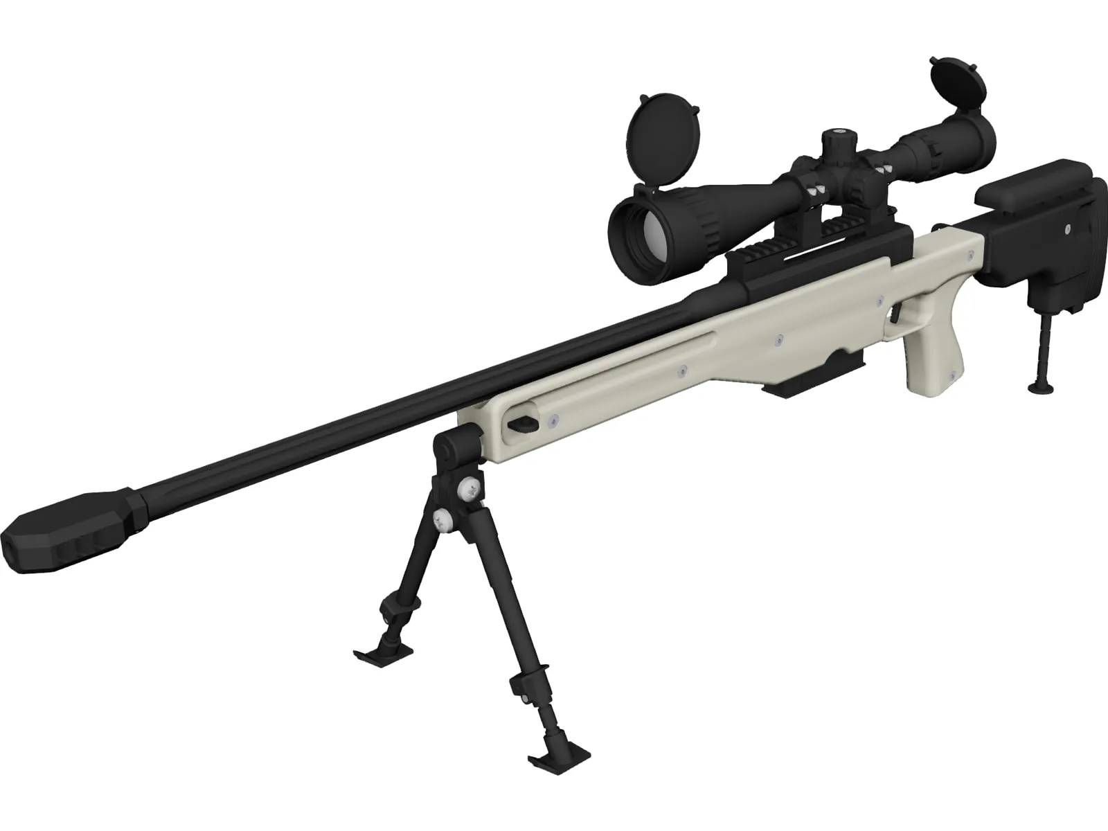
Looking for a highly detailed 3D model of the .338 Lapua Magnum Sniper Rifle for your mechanical engineering, simulation, or visualization projects? Download this precision-engineered CAD assembly ready for multi-platform integration.

Key Features:

  • Accurate Mechanical Design: Ideal for ergonomics analysis, component placement, clearance testing, and high-quality rendering.
  • Universal Software Compatibility: Fully adaptable across major CAD environments for quick workflow integration.

Supported CAD Formats:

Compatible with SolidWorks, Autodesk Inventor, CATIA, Siemens NX, PTC Creo, AutoCAD, Pro/ENGINEER, ACIS (SAT), and STEP/IGES format viewers.


Continue Reading | ความคิดเห็น

Fusion 360 Body vs. Component: The Ultimate 3D CAD Guide

Tuesday, September 1, 2026

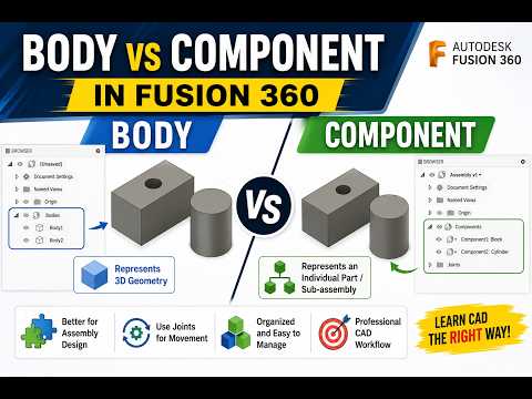
When diving into modern 3D CAD software like Autodesk Fusion 360, one of the first major hurdles beginners encounter is understanding the difference between a Body and a Component. While both represent 3D geometry on your screen, treating them as interchangeable is a common mistake that can derail your design workflow later on.

Let's break down these core concepts with practical examples so you can structure your models with confidence.

What is a Body?

In Fusion 360, a Body is a single, continuous 3D solid or surface object. Think of a body as a lump of clay or a solid block of material. You can extrude, cut, combine, and fillet bodies to build complex physical geometry.

However, bodies have strict structural limitations: - They cannot have motion joints applied directly to them. - They do not possess their own independent coordinate system (origin). - They are best suited for initial modeling steps, single-part designs, or temporary geometric tools.

What is a Component?

A Component is a self-contained organizational unit that holds geometry (bodies), sketches, construction planes, and its own unique origin. If a body is a single piece of material, a component is a complete functional part or sub-assembly.

Key features of components include: - Joints and Motion: Components can be moved relative to each other using joints to simulate real-world mechanical motion. - Assembly Structure: Components appear as distinct items in Bills of Materials (BOM) and technical drawings. - Reusability: You can create multiple instances of a component; editing one automatically updates all other instances.

Key Differences at a Glance

To streamline your 3D CAD workflow, keep these distinctions in mind: 1. Motion & Mechanics: Need your parts to articulate or move? You must use components to apply joints. 2. Drawings & Metadata: Creating detailed assembly documentation? Only components carry distinct part numbers and metadata. 3. Hierarchy: Bodies reside inside components. A component can contain multiple bodies, but a body cannot contain a component.

Best Practice: The Golden Rule

A great rule of thumb in Fusion 360 is to create a new component before you start sketching whenever you are designing a multi-part assembly. This habit keeps your browser tree organized, avoids timeline errors, and builds a professional 3D CAD design structure from the very beginning.

By mastering when to use bodies versus components, you'll create cleaner, more flexible, and fully functional 3D models every time!

3D CAD
Continue Reading | ความคิดเห็น

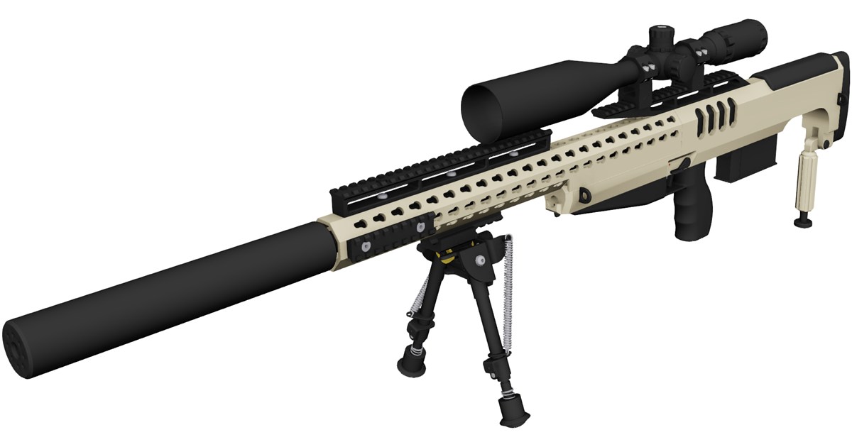
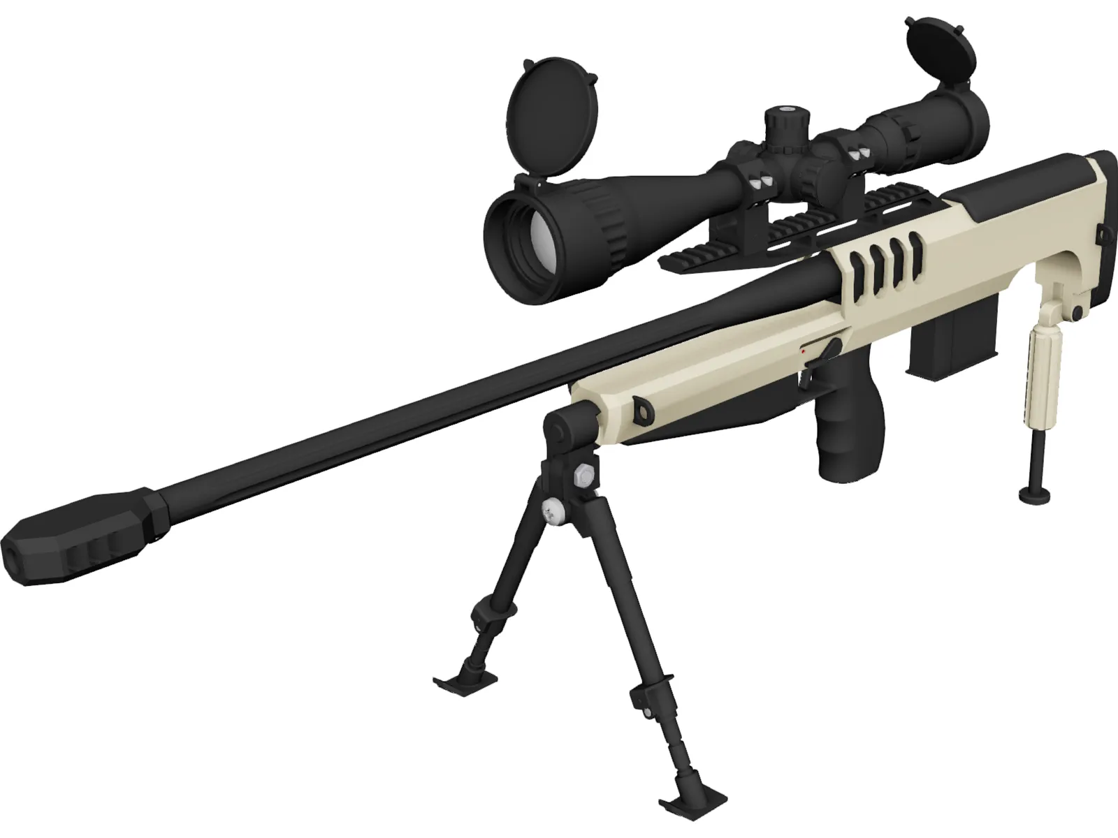
.338 Lapua Magnum Sniper Rifle 3D CAD Model Download

Preview ImagePreview ImagePreview Image

Enhance your defense engineering, mechanical design, and simulation projects with this highly detailed .338 Lapua Magnum Sniper Rifle 3D CAD model. Engineered for precision visual rendering, spatial modeling, and assembly integration, this model serves as an ideal reference for long-range precision rifle components.

Key Features & Capabilities

  • High Precision Geometry: Accurately captures the structural elements, stock, barrel, and receiver profile of the classic bolt-action .338 Lapua Magnum platform.
  • Engineering & Simulation Ready: Suitable for digital prototyping, ergonomic studies, clearance testing, and visual presentations.
  • Universal Interoperability: Easily converted and scaled across major commercial CAD environments.

Supported CAD Software Formats

This 3D model is compatible with a wide array of industry-standard computer-aided design packages, including:

  • SolidWorks & Autodesk Inventor
  • AutoCAD & ACIS (.sat)
  • PTC Creo / Pro/ENGINEER
  • CATIA & Siemens NX
  • Neutral STEP, IGES, and Mesh formats

Continue Reading | ความคิดเห็น

The Ultimate Beginner’s Guide to Free 3D CAD: Download, Install, and Master Design

In today's fast-paced digital era, architecture, engineering, and product development rely heavily on advanced software solutions. Whether you are an aspiring engineer, an architect, or a hands-on maker, learning how to use 3D CAD software is an essential step toward turning your creative concepts into precise, physical reality. From computer-aided manufacturing (CAM) to Building Information Modeling (BIM), modern design tools have revolutionized how we build and innovate.

What is 3D CAD and Why Should You Use It?

Computer-Aided Design (CAD) allows creators to construct detailed two-dimensional drawings and complex three-dimensional digital models. Utilizing powerful 3D CAD software enables designers to visualize objects in a realistic virtual environment before manufacturing begins. This significantly reduces costly design errors, optimizes material usage, and accelerates overall production workflows across architecture, product design, and mechanical engineering.

Key Applications: From BIM to CAM CNC

Understanding CAD is just the beginning. Once you master the fundamentals of digital modeling, you unlock access to several interconnected disciplines:

  • Building Information Modeling (BIM): Architects and civil engineers use spatial modeling to design smarter infrastructure, manage building lifecycles, and collaborate seamlessly across multidisciplinary teams.
  • CAM CNC Machining: Computer-Aided Manufacturing (CAM) translates digital 3D models into toolpaths and code that Computer Numerical Control (CNC) machines use to cut, drill, and shape physical materials with extreme precision.

How to Download and Install Your Free CAD Software

Getting started with professional design tools does not have to break the bank. Follow these simple steps to safely download and install your software:

  1. Check System Requirements: Ensure your computer meets the graphics card, RAM, and processor specifications required for rendering 3D models smoothly.
  2. Download the Installer: Visit the official software website or trusted source to download the official setup package.
  3. Run the Setup Wizard: Launch the downloaded installer file and follow the on-screen prompts to complete the installation process.
  4. Initial Configuration: Launch the application, configure your workspace layout, and select your preferred measurement units (metric or imperial).

Final Thoughts

Embracing modern 3D CAD tools unlocks endless possibilities for innovation across engineering, architecture, and manufacturing. By following this simple setup guide, you take your first step toward mastering digital modeling, BIM workflows, and CNC manufacturing today!

3D CAD
Continue Reading | ความคิดเห็น

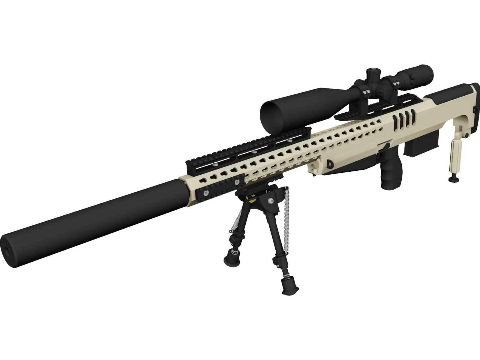
.338 Lapua Magnum Bullpup SD 3D CAD Model Download

Preview ImagePreview ImagePreview Image

Download a high-precision 3D CAD model of the .338 Lapua Magnum Bullpup SD rifle assembly. Designed for mechanical engineers, product designers, and 3D modeling professionals, this model provides accurate component geometry suitable for digital mockups, ergonomic testing, and rendering.

Key Features & Software Compatibility:

  • Multi-Format Support: Compatible with major CAD software including SolidWorks, AutoCAD, Autodesk Inventor, PTC Creo (Pro/E), Siemens NX, CATIA, and ACIS formats.
  • Detailed Mechanical Layout: Captures the compact, suppressed (SD) bullpup configuration chambered in the powerful .338 Lapua Magnum cartridge.
  • Engineering & Design Ready: Ideal for visual rendering, structural studies, component fitting, and simulation environments.

Continue Reading | ความคิดเห็น

Getting Started with Free 3D CAD: A Complete Download and Setup Guide

Computer-aided design has revolutionized how architects, engineers, and makers bring their creative ideas to life. Whether you are designing mechanical parts, planning architectural structures, or preparing models for CNC machining, using reliable 3D CAD software is essential. Fortunately, getting access to powerful design tools does not always require a heavy financial investment.

Why Explore Free CAD Software?

For beginners and seasoned professionals alike, free and open-source design tools offer an accessible gateway into digital craftsmanship. Modern free CAD applications provide robust feature sets that cover everything from basic 2D drafting to complex 3D modeling, Building Information Modeling (BIM), and Computer-Aided Manufacturing (CAM/CNC) integration. Learning these tools allows creators to bridge the gap between conceptual sketches and physical production without any upfront software costs.

How to Download and Install Free CAD 1.1

Getting started with your software installation is straightforward when following a clear process. In our comprehensive video guide, you will be walked through the essential steps to get your environment up and running:

  • Locating the Installer: Access the official download source to guarantee a clean, secure file.
  • Executing the Setup: Follow the guided installer prompts, selecting options optimized for your operating system.
  • Configuring Your Interface: Customize initial settings, workspace layouts, and measurement units to suit your specific project needs.

Applications Across Architecture, BIM, and CAM CNC

Once configured, a capable 3D CAD platform unlocks possibilities across multiple industries. Architects can create precise BIM floor plans and 3D spatial models, while product designers can draft intricate components suitable for 3D printing. Additionally, built-in CAM and CNC support enables woodworkers and machinists to convert digital designs into accurate toolpaths for automated manufacturing.

Start Creating Today

You do not need an expensive software subscription to start creating professional-grade digital models. By taking advantage of accessible, high-performance tools, you can develop your drafting and engineering skills at your own pace. Check out the step-by-step video guide to download, install, and master your 3D CAD workflow today!

3D CAD
Continue Reading | ความคิดเห็น

.338 Lapua Magnum Bullpup 3D CAD Model: High-Precision Design Files

Preview ImagePreview ImagePreview Image

Explore and download a detailed .338 Lapua Magnum Bullpup 3D CAD model tailored for mechanical engineers, product designers, and 3D modeling enthusiasts. This high-precision model captures the ergonomic efficiency of the bullpup configuration combined with the robust specs of the .338 Lapua Magnum platform.

Key Features & Specifications

  • Configuration: Compact bullpup layout featuring integrated receiver, barrel, and stock geometry.
  • High Precision: Modeled with accurate proportions suitable for digital prototyping, spatial analysis, and rendering.
  • Universal Interoperability: Formatted for seamless import into top-tier CAD and BIM workflows.

Supported File Formats & Software

This 3D model is compatible with a wide array of industry-standard computer-aided design software, including:

  • SolidWorks, Autodesk Inventor, AutoCAD
  • PTC Creo / Pro/ENGINEER
  • Siemens NX, CATIA
  • ACIS (.sat) and standard neutral exchange formats

Perfect for engineering study, ergonomic research, and high-quality 3D visualization projects.


Continue Reading | ความคิดเห็น

Get Started with Free 3D CAD Software: Download & Installation Guide

Are you looking to dive into the world of digital design, architecture, or precision manufacturing without breaking the bank? Whether you are an aspiring architect, a mechanical engineer, or a passionate maker, finding a reliable 3D CAD software is the crucial first step in bringing your creative ideas to life. In this quick guide, we will walk you through downloading, installing, and setting up free CAD tools to kickstart your design journey.

Why Start with Free CAD Software?

Modern computer-aided design has evolved rapidly over the past few years. Powerful design capabilities are no longer locked exclusively behind expensive corporate software licenses. By utilizing modern 3D CAD platforms, creators can seamlessly transition from basic 2D drafting to complex, highly accurate three-dimensional modeling.

Free CAD software provides access to robust features, enabling users to explore multiple disciplines: - Architectural & BIM Design: Build detailed layout plans, structural models, and Building Information Modeling (BIM) data. - CAM & CNC Manufacturing: Translate 3D models into precise toolpaths for Computer-Aided Manufacturing (CAM) and CNC machining. - 3D Printing & Prototyping: Export clean digital files ready for immediate 3D printing and physical prototyping.

How to Download and Install Free CAD 1.1

Getting started with your installation is quick and straightforward. Follow these steps to set up your workspace correctly:

  1. Download the Official Installer: Always obtain the software package from a secure, verified source to ensure you receive the complete build and latest updates.
  2. Check System Requirements: Verify that your system meets the recommended GPU and RAM specifications to ensure smooth rendering and modeling performance.
  3. Execute the Setup: Open the downloaded setup file, accept the license terms, and follow the installer prompts to choose your installation directory.
  4. Initial Configuration: Launch the application, select your preferred interface mode (such as BIM, Mechanical, or Architectural), and configure your units of measurement.

Elevate Your Design Capabilities Today

Mastering computer-aided design opens up endless opportunities across engineering and creative fields. With integrated tools for BIM, 3D modeling, and CNC production, free software empowers you to take control of the entire production process from concept to creation.

Download the software today, set up your workstation, and start optimizing your 3D CAD workflows to turn your vision into reality!

3D CAD
Continue Reading | ความคิดเห็น

Next-Gen 3D CAD Viewing and AI Analysis: Secure In-Browser Innovation

Monday, August 31, 2026

In today's fast-paced engineering environment, manufacturing industries are looking for faster ways to analyze and visualize 3D CAD models. However, many companies face a major hurdle before they can even begin: balancing cutting-edge technology with strict data privacy regulations. Proprietary design data is exceptionally sensitive, making cloud-based uploads a dealbreaker for security-conscious organizations.

Powerful Visualization Directly in Your Browser

CADAS solves this fundamental challenge by providing a seamless solution that allows engineers to open and inspect 3D CAD files directly within their web browser. Traditional workflows often require installing heavy desktop applications or risking intellectual property exposure by uploading files to third-party servers.

With CADAS, complex STEP files are processed entirely on your local machine. Because your design files never leave your PC, enterprise-grade data security is guaranteed without sacrificing the convenience and speed of modern web applications. You get high-performance, real-time visualization right in your browser window.

Unleashing AI Insights Without Compromising Security

While viewing models efficiently is crucial, the real transformation happens when design data meets artificial intelligence. Manufacturers increasingly want to utilize AI to automate cost estimations, identify geometric flaws, and optimize manufacturability. Unfortunately, most conventional AI tools require sending valuable CAD assets to external cloud networks.

CADAS bridges this gap by enabling secure, local AI analysis. By combining localized browser processing with advanced 3D CAD analytics, engineering teams can instantly extract critical manufacturing insights, detect potential production bottlenecks, and streamline design reviews—all while keeping their intellectual property completely offline.

The Future of Secure Engineering Workflows

The future of digital manufacturing lies at the intersection of instant accessibility, intelligent automation, and absolute data privacy. By keeping your design files local while providing browser-based freedom and AI capabilities, CADAS removes the security barriers holding engineering teams back.

It is time to elevate your engineering pipeline: inspect your STEP files effortlessly and unlock the true potential of browser-based AI analysis today.

3D CAD
Continue Reading | ความคิดเห็น

Top SolidWorks Tips to Elevate Your 3D CAD Modeling Skills

Whether you are a seasoned mechanical engineer or a passionate beginner entering the digital design world, mastering SolidWorks is crucial for producing efficient, high-quality models. As industry standards continue to evolve, staying updated with quick tips and tricks can dramatically speed up your workflow and enhance your technical output.

Why SolidWorks Leads the 3D CAD Industry

SolidWorks remains one of the most powerful and intuitive software solutions used globally across automotive, aerospace, and product design sectors. Utilizing modern 3D CAD tools allows designers to transform complex concepts into precise, functional models with unmatched parametric accuracy. By leveraging advanced assembly techniques, surface modeling, and structural simulations, you can bring even the most intricate engineering visions to life seamlessly.

Essential Tips for Efficient 3D Modeling

To get the most out of your parametric design process, consider integrating these practical habits into your daily workflow:

  1. Optimize Your Sketching: Always fully define your sketches using smart dimensions and geometric relations. This prevents unexpected errors later in the design tree when making parametric modifications.
  2. Master Shortcut Keys: Customize your 'S' key menu and mouse gestures. Minimizing the time spent searching for features on the ribbon toolbar will double your modeling speed over time.
  3. Keep Feature Trees Clean: Name your key features and group related operations into logical folders. A well-organized feature manager tree makes team collaboration smooth and simplifies future revisions.
  4. Utilize Standard Configurations: Take advantage of SolidWorks configurations to create multiple variations of a single part or assembly within one file, saving both time and storage space.

Elevating Your Design Workflow

Mastering 3D CAD software is not just about learning which buttons to press; it is about adopting a structured design mindset. By practicing efficient modeling strategies and continually exploring quick tips, you can significantly reduce design cycle times, minimize manufacturing errors, and create realistic visual prototypes that stand out.

Start implementing these essential SolidWorks tips today, and watch your 3D CAD design efficiency soar to new heights!

3D CAD
Continue Reading | ความคิดเห็น

Master SolidWorks: Essential 3D CAD Modeling Tips for Beginners and Pros

SolidWorks remains one of the most powerful and widely used tools in modern engineering and product design. Whether you are an aspiring maker or an experienced mechanical engineer, mastering 3D CAD software is essential for bringing creative concepts into precise, functional models. From basic geometric sketches to complex parametric assemblies, honing your workflow saves valuable development time while boosting overall project accuracy.

Key SolidWorks Techniques for Speed and Precision

Creating clean, scalable models requires more than just knowing where tools are located—it requires a strong understanding of design intent. Here are fundamental practices to streamline your drafting process:

  • Fully Define Your Sketches: Always ensure your 2D profiles are fully constrained using smart dimensions and geometric relations (such as concentric, parallel, or equal). This prevents accidental shifts later in the design tree.
  • Maintain an Organized Feature Tree: Keep your feature manager organized. Rename key features, group related operations, and avoid unnecessary extrusions or cuts to make future edits hassle-free.
  • Leverage Shortcuts and Hotkeys: Customizing mouse gestures and keyboard shortcuts for frequently used tools like Extrude, Revolve, and Smart Dimension will dramatically speed up your execution.

Elevating Your Projects with Modern 3D CAD Workflows

As you advance beyond basic shapes, adopting structured 3D CAD workflows will significantly improve the quality of your output. Utilizing tools such as global variables and equations allows your models to adapt dynamically whenever specifications change. Furthermore, paying attention to surface fillets and visual materials helps convert basic technical parts into realistic visual assets suitable for presentations.

Consistently practicing these tips ensures your designs are not only visually impressive but also optimized for prototyping, 3D printing, and manufacturing. Investing time in mastering modern 3D CAD capabilities is the best way to sharpen your skills and stand out in the competitive design industry.

3D CAD
Continue Reading | ความคิดเห็น

Mastering Jewelry Design: Crafting a Stunning Krishna Pendant with 3D CAD

Jewelry design has evolved into a breathtaking blend of traditional craftsmanship and digital innovation. Crafting intricate, sacred pieces like a Lord Krishna pendant requires both artistic devotion and exceptional technical precision. Today, the power of modern 3D CAD technology makes it easier than ever for designers to transform complex concepts into photorealistic digital models ready for production.

Designing the Sacred Krishna Pendant

Designing devotional jewelry demands meticulous attention to detail. From the iconic peacock feather and flute to the subtle curves of divine features, utilizing advanced 3D CAD software allows designers to capture delicate elements with unmatched accuracy. Computer-aided design gives artists full creative freedom to experiment with filigree work, surface textures, and gemstone placements long before physically casting the metal.

Bringing Jewelry to Life: Rendering and Animation

Once the digital model is complete, the true visual transformation begins through rendering and animation. High-end rendering software enables designers to apply realistic metal finishes—such as rich yellow gold, warm rose gold, or sleek platinum—and simulate natural studio lighting on every surface.

Creating smooth 360-degree animations brings the Krishna pendant to life from every angle. These animations are not only captivating for potential clients and buyers but also serve as incredible visual material for jewelry CAD design tutorials. Viewers can see every intricate fold of drapery and fine detail in action.

Why Digital CAD Workflows Revolutionize Jewelry Making

Transitioning to digital design tools offers massive advantages for both custom jewelry businesses and CAD enthusiasts: - Unmatched Precision: Ensures accurate dimensions for gem setting and casting. - Enhanced Efficiency: Reduces physical prototyping costs and avoids costly manufacturing errors. - Seamless Visualizing: Allows clients to view accurate 3D renders and request modifications effortlessly.

Whether you are a seasoned goldsmith or a beginner following digital modeling tutorials, mastering 3D CAD skills is essential for turning divine inspiration into wearable art. Dive into 3D jewelry design today and elevate your creative craft to new heights!

3D CAD
Continue Reading | ความคิดเห็น

Popular Posts Today

 
Support : 3Dcadbrowser | Grabcad | 3Dcontentcentral | D | E | F | G
Copyright © 2028. Engineering 3DCad Appication - All Rights Reserved