Cad 3D Category

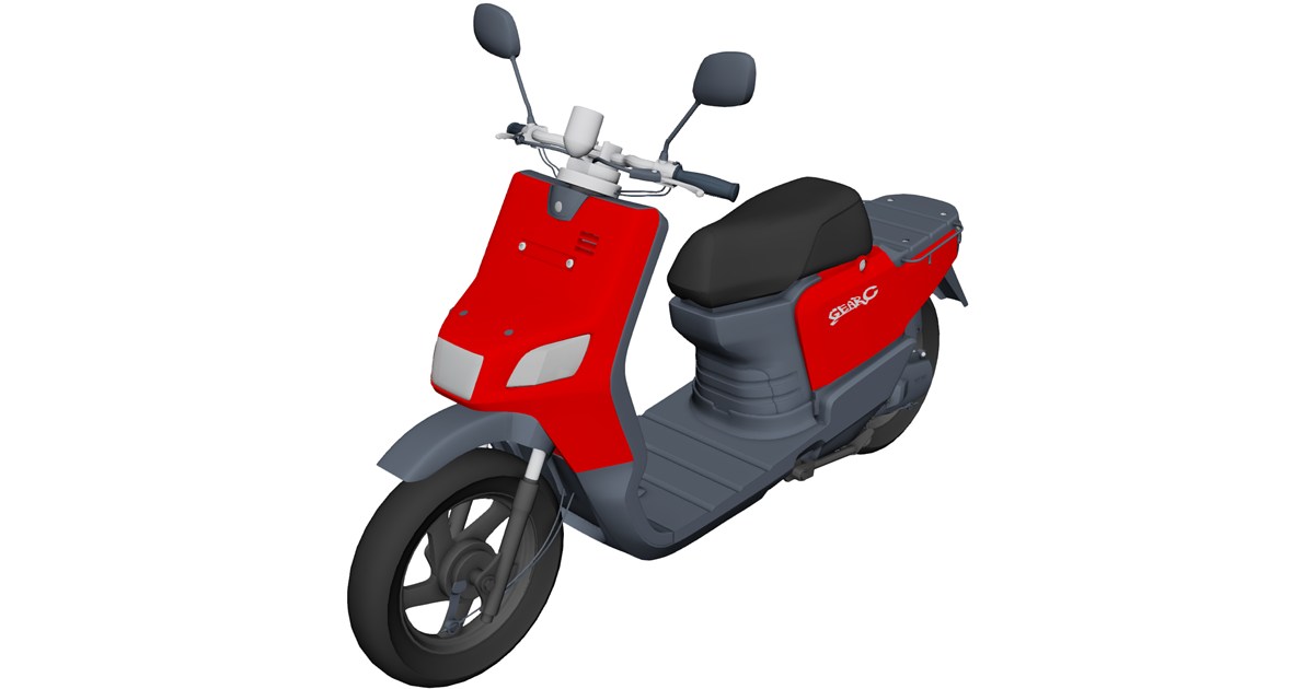
Scooter 3D Model Download: High-Quality Asset for CAD, Maya, Blender & Game Engines

Monday, August 24, 2026

Preview Image

Enhance your 3D visualization, game design, or engineering projects with this high-quality Scooter 3D Model. Designed for versatile use across digital content creation (DCC) tools and real-time engines, this asset provides clean geometry and realistic proportions.

Key Features & Specifications:

  • Universal Compatibility: Optimized for seamless import into 3ds Max, Maya, Blender, Cinema 4D, Unreal Engine, Unity, and major CAD/3D software packages.
  • Versatile Application: Ideal for architectural rendering, urban environment design, animations, VR/AR simulations, and game development.
  • Production-Ready: Detailed mesh design tailored for rendering efficiency and performance across different pipelines.

Download this versatile 3D scooter asset today to streamline your modeling workflow and bring realistic transportation details to your virtual scenes.


Continue Reading | ความคิดเห็น

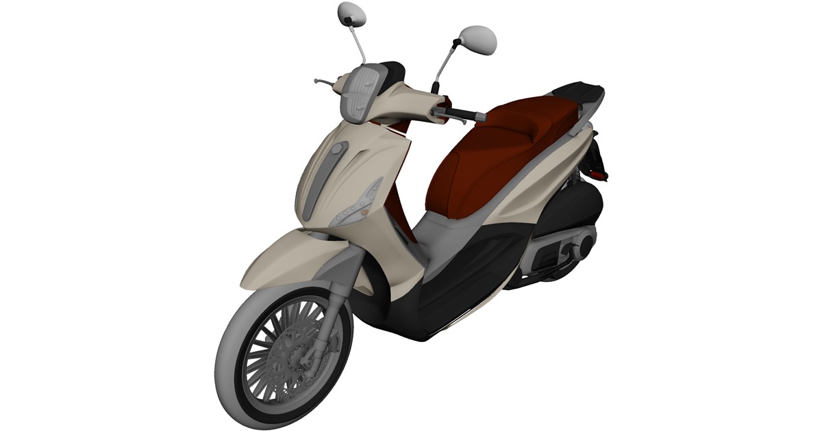
Piaggio Beverly Tourer 200cc Scooter 3D Model Asset

Preview Image

Enhance your urban environment visualizations, game levels, or animation projects with the high-quality Piaggio Beverly Tourer 200cc Scooter 3D Model. This asset captures the classic geometry and sleek styling of the iconic Italian touring scooter.

Model Features & Compatibility:

  • Software Support: Ready for import into 3ds Max, Maya, Blender, Cinema 4D, Unreal Engine, and Unity.
  • Use Cases: Ideal for architectural visualization, real-time game engines, VR/AR experiences, and digital CGI scenes.
  • Geometry: Detailed exterior bodywork, wheels, and ergonomic seating contours suitable for close-up renders.

Integrate this versatile vehicle asset into your pipeline to save production time on realistic transportation props.


Continue Reading | ความคิดเห็น

CadQuery vs OpenSCAD: Which Code-Based 3D CAD Tool Is Best?

Code-driven modeling has revolutionized how makers, engineers, and digital artists approach mechanical design and additive manufacturing. Unlike traditional drag-and-drop geometric editors, programmatic modeling tools allow users to build precise, parameter-driven models using code. When evaluating open-source, code-based 3D CAD solutions, two prominent software options lead the space: OpenSCAD and CadQuery.

Here is a breakdown of how these two powerful tools compare to help you decide which one fits your workflow best.

OpenSCAD: The Lightweight Classic

OpenSCAD has long been the standard for code-driven parametric design. It operates using its own dedicated domain-specific scripting language, making it relatively straightforward for beginners to learn basic geometric operations.

Key Advantages: - Ease of Entry: A simple syntax that makes creating basic parametric shapes fast and straightforward. - Vast Community: A massive user base with thousands of existing open-source scripts, libraries, and online tutorials. - Fast Setup: Lightweight, standalone application that runs smoothly on almost any system.

Drawbacks: - Language Limitations: Lacks standard programming constructs like object-oriented design or rich third-party library integration. - Geometry Engine: Relies primarily on Constructive Solid Geometry (CSG), which can make complex filleting and chamfering challenging.

CadQuery: The Python-Powered Evolution

CadQuery is a modern, Python-based framework designed to elevate programmatic modeling. Powered by the industrial-grade Open CASCADE geometry kernel, it utilizes Boundary Representation (B-Rep) to generate highly complex mechanical shapes.

Key Advantages: - Full Python Integration: Leverage the vast Python ecosystem, including math libraries, external data sources, and advanced scripting capabilities. - Robust Kernel: Superior handling of organic curves, complex fillets, shells, and direct STEP/IGES file exports. - Human-Readable Syntax: Uses a fluent script interface designed to produce clean, maintainable code.

Drawbacks: - Steeper Learning Curve: Requires a working knowledge of Python and environment setup. - Smaller Ecosystem: While growing rapidly, it has fewer ready-to-use community scripts than OpenSCAD.

Final Verdict: Choosing the Right 3D CAD Software

Selecting the best programmatic 3D CAD platform depends on your background and project scope. If you need a quick, easy-to-learn tool for basic 3D printing models, OpenSCAD is a reliable and time-tested option. However, if you already know Python and require professional-grade engineering features like step file outputs and precise fillets, CadQuery represents the next generation of code-driven 3D CAD design.

3D CAD
Continue Reading | ความคิดเห็น

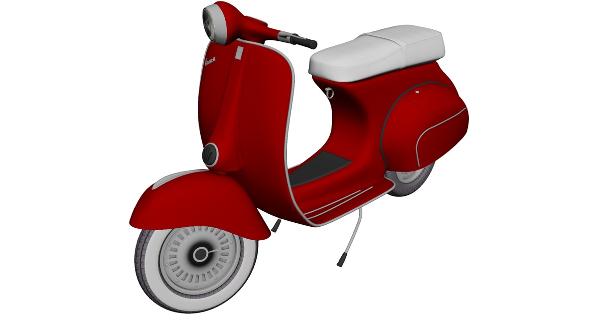
Classic 1962 Piaggio Vespa 3D Model | Download for Blender, Maya & 3ds Max

Sunday, August 23, 2026

Preview Image

Bring vintage Italian design into your digital projects with the 1962 Piaggio Vespa 3D Model. This detailed digital asset captures the iconic curves and timeless aesthetic of the classic 1960s scooter, making it an excellent addition for photorealistic rendering, game design, CGI animation, and virtual reality (VR) environments.

Key Features & Specifications:

  • Software Compatibility: Works seamlessly with 3ds Max, Maya, Blender, Cinema 4D, Unreal Engine, Unity, and other major 3D packages.
  • Use Cases: Ideal for historical scenes, urban background props, interactive games, architectural visualizations, and motion graphics.
  • Versatile Geometry: Production-ready model structure optimized for scene integration and customization.

Download this classic 1962 Piaggio Vespa model to upgrade your 3D asset library today.


Continue Reading | ความคิดเห็น

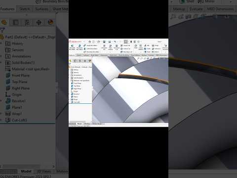
Mastering SolidWorks: Essential 3D CAD Modeling Tips for Designers

Computer-Aided Design has revolutionized how engineers, product designers, and digital artists transform abstract ideas into tangible reality. Among the vast array of design software available today, SolidWorks stands out as an industry standard. Whether you are crafting complex mechanical assemblies, automotive parts, or sleek consumer products, mastering 3D CAD tools is essential for staying competitive in modern manufacturing and engineering.

In this guide, we will explore key tips and techniques to help you optimize your SolidWorks workflow and elevate your modeling skills.

Why SolidWorks Dominates Modern Product Design

SolidWorks is renowned for its intuitive interface and powerful parametric modeling capabilities. From automotive engineering to digital art, professionals rely on 3D CAD software to create precise, scalable models. By leveraging features like dynamic sketching, smart dimensioning, and feature history, designers can quickly iterate and refine their concepts without starting from scratch.

Essential Tips to Streamline Your SolidWorks Workflow

To maximize efficiency and minimize design errors, consider implementing these fundamental modeling strategies:

  • Master Fully Defined Sketches: Always ensure your 2D sketches are fully defined with geometric relations and smart dimensions before applying 3D features. This prevents accidental shifts in geometry during future modifications.
  • Leverage Mouse Gestures and Hotkeys: Customize your gesture wheel and keyboard shortcuts for your most frequently used tools. Reducing cursor travel time can drastically speed up your modeling process.
  • Keep Your Feature Tree Organized: Name key features and group components logically. A clean, well-organized feature tree makes it significantly easier to edit complex parts and collaborate with team members.
  • Utilize Patterns and Symmetry: Avoid modeling repetitive geometry manually. Use linear, circular, and mirror feature patterns to save time and guarantee precision across your model.

Final Thoughts

Becoming proficient in 3D CAD requires continuous practice and an eagerness to adopt smart modeling habits. By applying these practical SolidWorks tips, you can enhance your design accuracy, streamline your production pipeline, and unleash your creative potential. Start implementing these techniques in your next project to experience a faster, more seamless modeling process!

3D CAD
Continue Reading | ความคิดเห็น

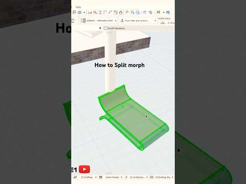
Mastering ArchiCAD: How to Split Morphs for Superior 3D CAD Design

ArchiCAD’s Morph Tool offers unmatched freedom when creating custom architectural elements, complex shapes, or conceptual geometry. However, working with intricate forms can sometimes feel overwhelming if you do not know how to manipulate them efficiently. Learning how to split a morph is an essential technique for anyone looking to refine their digital modeling workflow within modern 3D CAD environments.

Why Split Morphs in ArchiCAD?

When designing unique architectural features, a single morph object can quickly become difficult to edit as its complexity grows. By splitting a morph, you divide a complex shape into smaller, independent pieces.

This method enables you to shape any morph into a better, more precise form without affecting the entire model. Whether you need to apply different materials to specific sections, adjust unique angles, or create custom geometric cutouts, splitting gives you granular control over your design. Furthermore, breaking down complex geometry helps optimize model performance within your 3D CAD project.

Simple Steps to Split a Morph

Manipulating morphs in ArchiCAD is straightforward once you know the right procedure. Here is how you can easily split any morph:

  1. Select the Morph: In either the 3D window or the 2D floor plan view, select the morph object you wish to divide.
  2. Activate the Split Tool: Choose the Split tool (represented by the axe icon) from the editing toolbar.
  3. Draw the Splitting Line/Plane: Click to define the line or plane along which you want to cut through the morph geometry.
  4. Select the Element to Retain: Click on either side of the splitting line to complete the operation.

Once split, each portion becomes an individual morph element that can be further stretched, rotated, or sculpted independently.

Elevate Your Architectural Workflow

Mastering basic geometric manipulation is what separates novice modelers from efficient BIM professionals. Utilizing the split function allows you to seamlessly edit custom organic forms, roof structures, and detailed interior elements without starting from scratch.

By taking control of your geometry with this quick technique, you can elevate your modeling capabilities, save valuable time, and achieve a smoother, more flexible 3D CAD design workflow in ArchiCAD. Start applying this method to your project today to shape your ideas into perfection!

3D CAD
Continue Reading | ความคิดเห็น

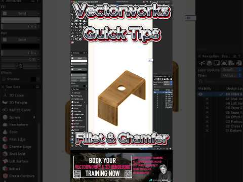
Speed Up Your 3D CAD Workflow: Vectorworks Fillet and Chamfer Guide

When designing complex objects or architectural elements, the secret to realism often lies in the details. Hard, razor-sharp edges rarely exist in the real world. That is where mastering edge-refinement tools becomes essential. If you are looking to elevate your 3D CAD modeling efficiency, understanding how to effectively use the 3D Fillet and Chamfer tools in Vectorworks is a game-changer.

What Are Fillet and Chamfer Tools?

In digital drafting, Fillet and Chamfer tools allow designers to quickly modify the sharp intersections of 3D solids:

  • 3D Fillet Tool: Rounds off sharp edges with a specified radius, creating smooth, curved transitions that mimic natural manufactured surfaces.
  • 3D Chamfer Tool: Cuts away an edge at a designated angle and distance, creating a clean, beveled slope.

Using these tools not only makes your digital models look significantly more realistic during rendering but also ensures accuracy for manufacturing and structural planning.

Quick Steps to Master Fillet and Chamfering in Vectorworks

To streamline your process in Vectorworks, follow these simple best practices:

  1. Select the Right Tool: Navigate to the 3D Modeling tool set and choose either the Fillet Edge or Chamfer Edge tool.
  2. Set Your Parameters: Before clicking on your model, enter your desired radius (for fillets) or setback distance (for chamfers) in the Tool bar settings.
  3. Select Edges Precisely: You can click individual edges, shift-click to select multiple edges, or choose entire faces to modify all surrounding edges simultaneously.
  4. Perform Non-Destructive Edits: Vectorworks maintains a parametric history. If you need to adjust the radius or distance later, simply double-click the object to edit the feature without starting from scratch.

Why These Tools Matter for Your 3D CAD Workflow

Integrating these quick modeling techniques into your daily routine drastically cuts down design time. Instead of manually constructing complex swept solids or subtractive shapes, a few clicks with the Fillet or Chamfer tools yield professional results instantly. Modern 3D CAD software relies on these intuitive operations to help designers focus on creativity rather than tedious geometry creation.

By incorporating these Vectorworks quick tips into your project routine, you will build cleaner models, render more realistic lighting, and deliver top-notch design presentations in a fraction of the time.

3D CAD
Continue Reading | ความคิดเห็น

The Ultimate Guide to 3D CAD for Precision CNC Manufacturing

In the fast-paced world of modern manufacturing, turning a rough concept into a high-precision physical component requires the right digital tools. Whether you are an experienced engineer, a machinist, or an enthusiastic hobbyist, mastering 3D CAD is the fundamental first step toward successful Computer Numerical Control (CNC) production.

From Digital Design to Physical Parts

Traditionally, manufacturing relied heavily on two-dimensional paper drawings, leaving plenty of room for interpretation and costly manual errors. Today, digital modeling software allows designers to construct virtual three-dimensional objects with microscopic precision.

These digital models serve as the master blueprint for modern machine tools. By converting solid geometries into machine-readable language (G-code), 3D CAD bridges the gap between creative design concepts and accurate physical manufacturing, ensuring every cut, drill, and pocket is executed perfectly.

Key Benefits of 3D CAD in Modern CNC Workflows

Integrating 3D modeling software into your manufacturing process offers several game-changing advantages:

  • Enhanced Visualization: Examine parts from every angle, inspect internal features, and verify proper fit within larger assemblies before cutting expensive raw material.
  • Reduced Material Waste: Simulate tool movements virtually to detect potential collisions, thin walls, or unreachable geometry early in the design stage.
  • Seamless CAM Integration: Effortlessly transfer your models directly into Computer-Aided Manufacturing (CAM) software to generate optimized toolpaths.

Tips for Creating Machine-Ready Designs

To ensure your digital drawings translate smoothly to the workshop floor, keep a few fundamental design rules in mind:

  1. Design for Tool Geometry: Standard CNC end mills are cylindrical. Always include internal radii on inside corners to accommodate round cutting tools.
  2. Maintain Reasonable Tolerances: Avoid over-specifying tight tolerances, as this significantly increases machining time and tool wear. Apply tight limits only where functional fit is critical.
  3. Optimize Wall Thickness: Keep structural integrity in mind. Extremely thin walls can vibrate or distort during the machining process under heavy cutting forces.

By incorporating robust 3D CAD practices into your product design workflow, you ensure higher manufacturing quality, faster project turnaround times, and lower overall production costs. Embrace modern digital modeling today to take your CNC projects to the next level!

3D CAD
Continue Reading | ความคิดเห็น

Master 3D CAD Design: Why Quality Training Matters for Your Career

Saturday, August 22, 2026

In today’s fast-paced engineering and architectural landscapes, simply enrolling in a computer-aided design course isn't enough to guarantee success. To build a thriving, future-proof career, aspiring designers need comprehensive, practical training that bridges the gap between theoretical knowledge and real-world application. Student reviews from leading technical institutes consistently highlight a crucial truth: quality instruction, hands-on practice, and expert mentorship make all the difference.

The Growing Demand for Advanced 3D CAD Expertise

Modern industries—ranging from civil engineering and product manufacturing to interior design—heavily rely on precise digital modeling. Learning 3D CAD empowers professionals to visualize complex spatial concepts, generate detailed digital prototypes, and optimize structural plans long before physical construction begins. As global design standards evolve toward automated and detailed workflows, mastering these advanced modeling skills has become an indispensable asset for modern technicians and engineers.

Beyond the Basics: What Student Reviews Reveal

When evaluating professional training programs, real feedback from course participants reveals what truly drives career growth. Merely completing lessons is only the beginning. Genuine professional advancement comes from working on interactive assignments, receiving personalized feedback from industry veterans, and mastering efficient software workflows.

Students frequently emphasize that top-tier institutes focus on building problem-solving capabilities rather than just memorizing software commands. Having dedicated mentors to guide you through intricate drafting challenges ensures that you gain actual project confidence rather than just a paper certificate.

Unlocking Global Opportunities with 3D CAD Skills

Investing your time in mastering modern 3D CAD tools opens doors to diverse, high-paying career paths across the globe. Whether your goal is to collaborate with international architectural firms, work in industrial manufacturing, or launch a freelance drafting business, specialized technical expertise will always set you apart from the competition.

To achieve long-term success in computer-aided drafting, choose a training provider that prioritizes practical skills and real student outcomes. Investing in the right learning environment today lays the foundation for a rewarding and impactful design career tomorrow.

3D CAD
Continue Reading | ความคิดเห็น

The Game-Changing Autodesk Secret Tip Every 3D CAD Designer Needs to Know

Whether you are a seasoned engineer or a hobbyist creating your first prototype, working with powerful software like Autodesk can sometimes feel overwhelming. However, mastering hidden feature shortcuts can transform your digital workspace overnight. If you want to elevate your design process, understanding the best 3D CAD techniques is essential for saving time, boosting precision, and reducing costly errors.

Why Small Tweaks Make a Big Difference

Autodesk software is packed with robust tools, yet many creators rely only on standard default settings. By uncovering lesser-known options—such as customized hotkeys, advanced parameters management, or dynamic workspace settings—you can dramatically streamline your design phase. Instead of manually repeating complex modeling steps, leveraging these built-in secrets allows you to focus on innovation rather than tedious menu navigation.

The Hidden Autodesk Tip You Need to Try

One of the most effective tricks in Autodesk involves optimizing your mesh export settings and parametric constraints before sending files to a 3D printer. Many designers face issues with broken geometry or incorrect tolerances after exporting their files.

By fine-tuning your default export density and taking advantage of direct editing capabilities, you can refine your geometry instantly without disrupting your design history. This simple adjustment ensures that your 3D CAD models transition smoothly from the digital screen to the physical print bed without losing critical dimensional accuracy.

Perfecting Your Prints with Smart Design Habits

Creating a flawless physical object requires more than just drawing basic shapes; it demands a strategy tailored specifically for additive manufacturing. When working with modern 3D CAD software, keeping wall thicknesses consistent, applying strategic fillets to stress-bearing edges, and checking for non-manifold geometry beforehand will save you hours of print failures and wasted material.

Final Thoughts

Unlocking simple yet powerful tips within Autodesk isn't just about working faster—it is about achieving higher-quality results with far fewer headaches. Try integrating these hidden workflow hacks into your next modeling session, and watch your project efficiency skyrocket.

3D CAD
Continue Reading | ความคิดเห็น

Mastering 3D CAD: The Ultimate Guide to Modern CNC Manufacturing and Drawing

In today's fast-paced industrial landscape, digital engineering has completely revolutionized how parts are designed, tested, and produced. At the very heart of this technological shift lies modern computer-aided design. Transitioning from traditional paper drafts to advanced 3D CAD software has empowered engineers, machinists, and hobbyists alike to create intricate, highly accurate models ready for automated production.

Why 3D CAD is Essential for CNC Manufacturing

Computer Numerical Control (CNC) machining relies heavily on precise geometric data to guide cutting tools along complex paths. Utilizing 3D CAD tools allows designers to construct a digital representation of a physical object long before a single piece of raw material is cut.

By visualizing parts in a fully dimensional digital environment, creators can easily detect design flaws, calculate material properties, and run real-time stress simulations. This process dramatically cuts down on prototype waste, lowers overall production costs, and accelerates the product development lifecycle. Furthermore, three-dimensional models seamlessly integrate with Computer-Aided Manufacturing (CAM) software, creating a smooth pipeline from initial concept to physical production.

Best Practices for Preparing CAD Drawings for Machining

To ensure your digital drawings translate perfectly onto the workshop floor, follow these essential design rules:

  • Design for Machinability: Keep tool paths in mind. Avoid internal sharp corners where standard round end mills cannot cut, and opt for generous fillets or relief undercuts instead.
  • Optimize Tolerances: Define clear manufacturing tolerances. While high precision is crucial for moving parts, unnecessarily tight limits across the entire design will significantly increase machining time and expense.
  • Export the Right File Formats: Standardize your export formats. Universal standard files like STEP or IGES retain precise surface and solid geometry, making them ideal for CAM software translation.

Conclusion

Whether you are an experienced manufacturing professional or a passionate creator, leveraging 3D CAD technology is the fastest way to turn complex ideas into tangible products. By combining smart digital modeling with efficient CNC workflows, you can produce precision components with unprecedented speed and accuracy. Start refining your CAD models today and elevate your manufacturing process to the next level!

3D CAD
Continue Reading | ความคิดเห็น

Mastering SolidWorks: Essential 3D CAD Tips for Smarter Modeling

Whether you are an aspiring mechanical engineer, an industrial designer, or a digital creator, mastering SolidWorks is one of the most effective ways to bring your ideas to life. In today's competitive design landscape, using 3D CAD software serves as the backbone for converting raw concepts into precise, functional models. However, building complex models efficiently requires more than just basic commands—it demands smart strategies and workflow optimization.

Master the Art of Parametric Sketching

Every great 3D model starts with a well-structured sketch. One of the most common mistakes is over-complicating initial sketches or leaving them under-defined. To build a robust model: - Keep Sketches Simple: Break complex geometry into smaller, modular features rather than packing everything into a single, cluttered sketch. - Utilize Geometric Relations: Instead of relying exclusively on dimensions, use constraints like parallel, concentric, and equal to preserve your core design intent. - Fully Define Sketches: Always aim for fully defined sketch entities before extruding or revolving to prevent accidental modifications down the line.

Streamline Your Feature Tree

To truly maximize the power of 3D CAD applications, organizing your feature tree is crucial. A clean tree makes editing and collaboration vastly easier. Rename important features, group related steps into folders, and make full use of symmetry tools like Mirror and Pattern. When working on dynamic designs, consider leveraging global variables and equations to quickly update key parameters across your entire model with a single edit.

Accelerate Workflow with Mouse Gestures and Shortcuts

Speed and precision should work together. SolidWorks offers customizable mouse gestures and keyboard shortcuts that give you instant access to your most frequently used commands. Minimizing menu navigation allows you to keep your focus on solving design challenges rather than hunting for tools.

Final Thoughts

Improving your modeling efficiency takes consistent practice, but integrating these core principles will significantly boost your productivity and accuracy. By continuously refining your skills within your 3D CAD workflow, you can elevate your designs from simple sketches to production-ready assets. Apply these tips to your next project and watch your modeling process become faster and more enjoyable!

3D CAD
Continue Reading | ความคิดเห็น

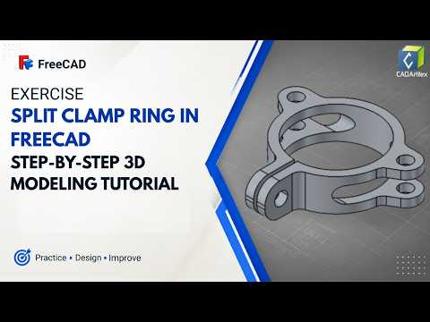
How to Design a Split Clamp Ring in FreeCAD: A Complete 3D CAD Guide

Friday, August 21, 2026

Split clamp rings are fundamental components in mechanical engineering, widely used to secure parts along shafts without causing surface damage. Whether you are building custom robotics, modifying industrial machinery, or 3D printing functional hardware at home, learning how to model this essential part is a valuable skill.

In this step-by-step tutorial, we demonstrate how to design a fully functional Split Clamp Ring using FreeCAD—one of the most powerful open-source 3D CAD software options available today.

Why Learn Split Clamp Ring Design?

Unlike standard solid collar rings that rely on set screws, split clamp rings use clamping force via mechanical fasteners to lock onto a shaft firmly. This design provides superior holding power and prevents wear on the shaft.

Modeling this specific geometry requires a solid grasp of parametric design, geometric constraints, and feature creation, making it an ideal practice project for anyone looking to build confidence in technical design.

Key Steps to Model the Clamp Ring in FreeCAD

  1. Setting Up the Base Profile: Start in the Part Design Workbench. Create a new body and draw two concentric circles in the Sketcher to define the inner shaft diameter and outer collar dimension.
  2. Extruding the Main Solid: Pad the sketch to your required height to create the primary cylindrical ring.
  3. Adding Mounting Lugs & Screw Holes: Create reference planes to model the clamping ears, counterbored screw holes, and threaded receiver holes for your hardware.
  4. Creating the Split: Use a thin rectangular pocket cut to remove a small section of material through one side of the ring, giving it the flexibility needed to clamp down when tightened.

Best Practices for Parametric Modeling

  • Fully Constrain Your Sketches: Always ensure your sketch dimensions and geometric constraints are fully defined. This guarantees stability when modifying your model later.
  • Leverage Parametric Flexibility: Design with variables in mind so you can quickly scale the inner diameter for different shaft sizes in future 3D CAD projects.

Conclusion

By mastering these fundamental modeling techniques in FreeCAD, you will gain practical experience that translates directly to real-world mechanical design. Watch the step-by-step video tutorial to follow along, refine your workflow, and take your modern 3D CAD skills to the next level!

3D CAD
Continue Reading | ความคิดเห็น

How to Open XMT_TXT Files in Your 3D CAD Software Easily

Have you ever received an .xmt_txt file from a colleague or client, only to find that Windows refuses to open it? If your system is blocking or failing to recognize these Parasolid files, you are certainly not alone. This issue is surprisingly common in design workflows, but resolving it is quick and straightforward.

In this guide, we will break down what an XMT_TXT file is and walk you through the simple steps to open it effortlessly in your 3D CAD software.

What is an XMT_TXT File?

An XMT_TXT file is a text-based CAD file generated by the Parasolid geometry modeling kernel, which powers many popular industrial design applications. Parasolid files typically carry standard extensions like .x_t (text format) or .x_b (binary format).

Sometimes, during export or file transfer, the extension gets altered to .xmt_txt. Because Windows does not immediately associate this specific extension with standard CAD viewers, it often blocks the file or fails to launch the appropriate application.

Why Windows Blocks Your Parasolid File

There are two main reasons Windows might prevent you from accessing an XMT_TXT file: 1. Unrecognized Extension: Your operating system does not automatically link .xmt_txt with installed software. 2. Security Blocks: Windows Security frequently restricts files downloaded from the internet or received via email attachments for safety.

Step-by-Step: How to Open XMT_TXT Files

Follow these simple troubleshooting steps to get your design files working again:

  1. Unblock the File: Right-click the .xmt_txt file, select Properties, and check the Unblock box near the bottom of the General tab if present. Click Apply and then OK.
  2. Rename the File Extension: The easiest workaround is changing the file extension manually. Right-click the file, choose Rename, and change the ending from .xmt_txt to .x_t. Windows will show a warning about changing extensions—click Yes to confirm.
  3. Import into Your Software: Launch your preferred 3D CAD program (such as SolidWorks, Siemens NX, or Autodesk Inventor) and use the File > Open or Import option to open the newly renamed .x_t file.
  4. Use a Dedicated Viewer: If you do not have a full modeling suite installed, you can use free tools like eDrawings Viewer or Parasolid-compatible web viewers to inspect the geometry.

Final Thoughts

Dealing with unexpected file formats can slow down project timelines, but opening Parasolid files does not have to be confusing. By simply adjusting file extensions and updating security settings, you can seamlessly import and manage any 3D CAD model without hassle.

3D CAD
Continue Reading | ความคิดเห็น

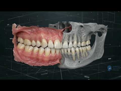
Precision Dentistry: How 3D CAD is Revolutionizing Digital Crown Lengthening Surgery

For years, crown lengthening was a procedure that relied heavily on a surgeon’s manual measurements and visual estimation. While effective, the margin for error was always a consideration. Today, the landscape of restorative and aesthetic dentistry has been transformed by the integration of digital workflows. By utilizing advanced 3D CAD software, dental professionals can now plan surgeries with a level of precision that was previously unimaginable.

What is Digital Crown Lengthening?

Digital crown lengthening is a procedure used to remove excess gum tissue and, in some cases, bone, to expose more of a tooth's surface. Whether it is for a "gummy smile" correction or to prepare a tooth for a functional crown, the digital approach ensures that the biological width is respected and the aesthetic outcome is predictable.

The process begins with a high-resolution intraoral scan and a CBCT (Cone Beam Computed Tomography) scan. These data sets provide a comprehensive view of both the soft tissue and the underlying bone structure.

The Power of 3D CAD in Surgical Planning

The core of this technological leap lies in the planning phase. By leveraging 3D CAD (Computer-Aided Design) tools, clinicians can create a "digital twin" of the patient’s mouth. This allows the surgeon to virtually design the new gum line and determine exactly how much bone needs to be contoured.

Because the planning happens in a digital environment, the dentist can simulate the final result and make adjustments before the actual procedure begins. This eliminates guesswork and ensures that the final restoration—be it a veneer or a crown—will fit perfectly within the newly established dimensions.

From Digital Design to Surgical Reality

Once the design is finalized within the 3D CAD environment, the data is used to manufacture a custom surgical guide, typically via 3D printing. This guide fits securely over the patient’s teeth during surgery, acting as a physical map for the dentist.

The guide indicates exactly where to make incisions and where to contour the bone. The benefits for the patient are numerous: * Reduced Surgery Time: The procedure is faster because the "decisions" were made during the planning phase. * Faster Healing: More precise incisions lead to less trauma to the surrounding tissue. * Superior Aesthetics: The final gum line is symmetrical and exactly as planned.

Digital crown lengthening represents the perfect marriage of biology and technology, offering patients a safer, more accurate, and highly aesthetic surgical experience.

3D CAD
Continue Reading | ความคิดเห็น

Unlocking the Power of 3D CAD: Real-World Applications in Engineering and Simulation

Have you ever looked at a complex mechanical assembly or a stunning dynamic animation and wondered, "Where can this actually be used?" In today's fast-paced industrial landscape, computer-aided design has evolved far beyond basic 2D drafting. By leveraging advanced 3D CAD technology, engineers and product designers can conceptualize, test, and refine intricate designs long before physical manufacturing ever begins.

From Concept to Motion: Animation and Simulation

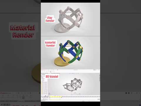
Modern engineering software like SolidWorks does much more than render static models. It empowers creators to run realistic simulations, test structural integrity, analyze stress points, and create smooth mechanism animations.

When you animate a functional design, you aren't just making a visually appealing video—you are validating motion and functionality. Stress testing a virtual prototype helps identify potential mechanical failures, optimize material usage, and drastically reduce physical prototyping costs. Integrating high-performance 3D CAD workflows ensures that every moving component interacts seamlessly, saving valuable time and capital during the product development lifecycle.

Where Can You Apply These Skills?

The ability to design, animate, and simulate dynamic systems opens doors across a wide variety of cutting-edge industries:

  • Automotive and Aerospace: Designing high-performance engine components, aerodynamic bodies, and landing gear mechanisms with sub-millimeter precision.
  • Robotics and Automation: Modeling robotic arms, automated assembly lines, and kinetic machinery to verify motion paths and prevent mechanical collisions.
  • Consumer Electronics: Crafting sleek, durable product enclosures that protect internal components while optimizing user ergonomics.
  • Medical Devices: Developing customized prosthetics, surgical tools, and life-saving equipment that require strict safety simulations and compliance.

Embrace the Future of Design

Whether you are an aspiring student, an independent designer, or an experienced engineer, mastering 3D CAD tools unlocks endless possibilities for innovation. As manufacturing standards shift toward virtual testing and digital twins, the ability to blend solid modeling with motion animation and simulation remains one of the most valuable skill sets in modern technology.

3D CAD
Continue Reading | ความคิดเห็น

Text to 3D CAD: How AI-Powered Multi-Agent Systems Are Changing Manufacturing

Thursday, August 20, 2026

Imagine describing a physical object in plain English and watching a complete, 3D printable file materialize in seconds. What once sounded like science fiction is now becoming a reality through cutting-edge artificial intelligence. Enter MAC (Multi-Agent CAD), an innovative system designed to bridge the gap between simple text prompts and functional manufacturing models.

What is Multi-Agent CAD (MAC)?

Traditional 3D CAD software often requires years of practice, precise mathematical inputs, and complex manual drafting. MAC changes this paradigm by using a collaborative network of specialized AI agents. Instead of relying on a single AI model to guess the exact geometry of an object, MAC splits the workload among multiple intelligent agents. Some agents analyze the text prompt, others generate the underlying parametric code, and additional agents inspect the design to ensure structural viability.

This multi-agent approach allows the system to generate clean, editable, and highly accurate parametric models rather than distorted 3D meshes. By translating descriptive text directly into code-based geometry, MAC creates physical parts that are optimized for production and ready for 3D printing.

Why Text-to-CAD Technology Matters

The integration of generative AI into 3D CAD workflows brings several major advantages to engineers, industrial designers, and hobbyists alike:

  • Rapid Prototyping: Turn creative concepts into physical objects without spending hours on initial sketching and baseline modeling.
  • Accessibility: Lower the barrier to entry, allowing non-experts to generate custom parts without navigating steep software learning curves.
  • Parametric Accuracy: Because MAC produces code-driven geometry rather than mere visual surfaces, the output remains fully customizable, precise, and structurally sound.

The Future of Digital Design

While human expertise remains essential for complex mechanical engineering, tools like MAC represent a massive leap forward for rapid design iteration. The future of 3D CAD is evolving into a hybrid process—one where humans provide creative intent and AI handles the tedious drafting tasks. Whether you are an experienced engineer or a desktop manufacturing enthusiast, text-driven CAD modeling is set to redefine how we bring digital ideas into the real world.

3D CAD
Continue Reading | ความคิดเห็น

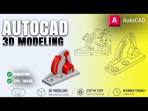
Step-by-Step 3D CAD Tutorial: Designing a Mechanical Mounting Bracket in AutoCAD

Are you looking to level up your mechanical engineering skills or master computer-aided design? Transitioning from 2D drafting to solid modeling is one of the most rewarding steps in modern engineering. By leveraging power-packed 3D CAD software like AutoCAD, you can transform flat conceptual sketches into highly accurate, detailed mechanical components ready for manufacturing.

In this practical guide, we will explore the fundamental steps and techniques required to model a detailed mechanical mounting bracket from scratch.

Essential Tools for Mechanical Solid Modeling

Creating robust mechanical parts relies on mastering a few core solid modeling operations. When working on a mounting bracket or similar mechanical component, you will frequently utilize:

  • Extrude: Convert basic 2D closed polylines into 3D solid shapes by adding height or depth.
  • Subtract: Hollow out sections, create bolt holes, or carve keyways by subtracting one solid shape from another.
  • Union & Intersect: Combine multiple distinct solids into a single unified object or extract overlapping geometries.

Understanding how these boolean operations interact allows you to build sophisticated components out of simple geometric primitives.

Designing a Mechanical Mounting Bracket Step-by-Step

To build a realistic mechanical mounting bracket, precision is key. Follow these practical stages during your modeling workflow:

  1. Draft the Base Profile: Start in a 2D view by sketching the base plate and side support ribs with exact dimensions.
  2. Convert to 3D: Apply the Extrude tool to give thickness to your base and vertical mounting walls.
  3. Add Fastener Holes: Draw 2D circles at the designated mounting points, extrude them through the solid body, and apply the Subtract command to generate precise screw clearance holes.
  4. Refine and Fillet: Smooth sharp outer edges using the Fillet Edge command to reduce stress concentrations in your 3D CAD model.

Tips for an Efficient Modeling Workflow

Mastering 3D CAD modeling requires both technical knowledge and disciplined habits. Always ensure your 2D sketches are properly closed before extruding to avoid mesh or surface errors. Additionally, utilize custom User Coordinate Systems (UCS) when placing features on angled surfaces, and regularly switch visual styles (from Wireframe to Conceptual or X-Ray) to inspect your model's internal geometry.

With consistent practice on real-world projects like mounting brackets, you will quickly develop the speed and confidence needed for professional mechanical design.

3D CAD
Continue Reading | ความคิดเห็น

Essential 3D CAD Practice: How to Model a Mechanical Mounting Bracket

Designing mechanical components requires precision, efficiency, and a solid grasp of core modeling tools. Whether you are an aspiring mechanical engineer or a seasoned draftsman looking to sharpen your skills, practicing real-world component design is the best way to improve. In this guide, we explore how to create a detailed mechanical mounting bracket, offering an ideal exercise to strengthen your 3D CAD abilities.

Fundamental Tools for 3D Mechanical Modeling

Building complex mechanical parts in AutoCAD relies on mastering a few fundamental 3D commands. A mounting bracket, for instance, tests your ability to combine base shapes, create precise cutouts, and align geometries effectively.

Key operations featured in this practice exercise include: - Extrude: Transforming 2D cross-sections into 3D solid objects. - Subtract: Removing internal geometries to create mounting holes, counterbores, and slots. - Presspull: Dynamically modifying faces and extruding bounded areas for rapid design iteration. - Union: Combining multiple distinct solids into a unified, single component.

By understanding how these tools interact, you can approach even the most intricate mechanical blueprints with clarity and confidence.

Step-by-Step Approach to the Bracket Design

To begin modeling the bracket, start by establishing the primary 2D profile. Accuracy at this stage is critical, as any dimensional error in the base sketch will carry over to the final 3D model.

  1. Draft the Base Profile: Draw the foundational 2D outline of the bracket using accurate dimensions and centerlines.
  2. Convert to 3D Solids: Apply the EXTRUDE or PRESSPULL command to add depth to the base plate and upright support structures.
  3. Incorporate Feature Cutouts: Utilize boolean operations like SUBTRACT to carve out bolt mounting holes and center clearance slots.
  4. Refine and Inspect: Apply fillets or chamfers to sharp edges to optimize structural integrity, then switch visual styles to inspect your solid model from multiple angles.

Elevate Your Mechanical Design Skills

Mastering modern 3D CAD workflows isn't just about learning software commands; it is about developing a structured, logical approach to 3D spatial problem-solving. Completing practical hands-on exercises helps bridge the gap between theoretical knowledge and workplace execution.

Take time to work through this mechanical mounting bracket exercise, experiment with varied dimensions, and continue building your proficiency in 3D CAD modeling today!

3D CAD
Continue Reading | ความคิดเห็น

Level Up Your 3D CAD Skills: Speed Battles, Tutorials, and Expert Tips

Are you ready to test your speed, efficiency, and precision in digital design? Whether you are a seasoned engineer, a passionate designer, or a student looking to enhance your skill set, pushing your boundaries in 3D CAD can be both thrilling and immensely rewarding.

Speed modeling battles have rapidly become the ultimate arena for creators to showcase their expertise under pressure. However, behind every lightning-fast modeler is a solid foundation built on proven workflows, keyboard shortcuts, and clever techniques.

The Thrill of Competitive Speed Modeling

What separates an average designer from a lightning-fast pro? It usually comes down to tool mastery, feature organization, and strategic planning before drawing the very first sketch. In fast-paced modeling competitions, participants face off against the clock to recreate complex parts accurately in record time.

Watching or participating in these live battles offers a unique window into how experts solve complex geometric problems on the fly. You get to observe different design approaches, clever constraint applications, and minimal-step techniques that you can immediately integrate into your own workflow.

Essential Tips to Supercharge Your Design Workflow

Speed is not merely about clicking fast; it is about working smart. To significantly boost your efficiency in 3D CAD, consider implementing these practical strategies into your routine:

  • Master Keyboard Shortcuts: Customizing and memorizing hotkeys for your most frequently used commands saves precious seconds on every feature setup.
  • Plan Before You Sketch: Spend a few moments analyzing the overall geometry and base features of a model before starting. A logical feature tree simplifies future edits and avoids rebuild errors.
  • Leverage Constraints Wisely: Fully constraining your sketches early on prevents unexpected model breaks down the line, saving you substantial troubleshooting time.

Join the Community and Test Your Limits

Whether you want to compete against top designers in live speed challenges or simply polish your workflow through step-by-step tutorials, continuous practice is key. Mastering 3D CAD software is an ongoing journey of learning, adapting, and refining your technique. Stay curious, keep practicing, and don't hesitate to put your modeling skills to the ultimate test!

3D CAD
Continue Reading | ความคิดเห็น

How to Download and Install 3D CAD Software: Complete Setup Guide for Windows and Mac

Whether you are an engineer, architect, or digital artist, having a reliable 3D CAD software package installed on your computer is essential for bringing your creative visions to life. From initial product drafting to complex architectural modeling, modern design programs rely on smooth integration with your operating system to deliver optimal performance.

However, navigating the download and installation process across different operating systems like Windows and macOS can sometimes present unexpected challenges. In this comprehensive setup guide, we will walk you through the essential steps to get your design software up and running without hassle.

Step 1: Check System Requirements and Prepare Your Device

Before beginning any installation, ensure your computer meets the hardware specifications required by your design program. High-performance drafting tools depend heavily on processing power, RAM, and graphics acceleration.

  • Windows Users: Verify that your graphics card drivers are fully updated to prevent rendering glitches and performance lag during intensive tasks.
  • macOS Users: Ensure operating system compatibility, particularly if your device uses Apple Silicon (M1/M2/M3 chips), to confirm whether the installer runs natively or requires translation layers like Rosetta 2.
  • Disk Space: Clear out temporary files and ensure you have sufficient free SSD or HDD space for both the installer and workspace cache.

Step 2: Downloading and Running the Installer

To protect your system from security risks, always download your 3D CAD software directly from official, trusted sources or authorized distributors.

  1. Locate the downloaded file (.exe for Windows or .dmg/.pkg for macOS) in your system’s Downloads directory.
  2. Launch the installer and grant the necessary administrator privileges when prompted by your operating system.
  3. Follow the installation wizard, choosing your preferred installation path and selecting any essential add-ons or driver plugins required for your workflow.

Step 3: Licensing and Initial Performance Optimization

Once the setup process is complete, launch the application for the first time. You will typically be prompted to sign in with your user account, enter a valid license key, or activate an educational or trial license.

After activating your product, take a few minutes to navigate to the preferences menu. Adjust your default unit measurements, graphics performance settings, and autosave intervals to match your hardware capabilities. With your 3D CAD environment fully configured, you are ready to jump straight into your next modeling project!

3D CAD
Continue Reading | ความคิดเห็น

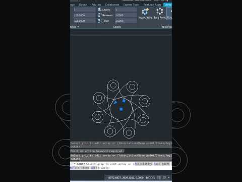
Master AutoCAD Polar Array: Create Precise Circular Patterns in 3D CAD

Wednesday, August 19, 2026

Designing symmetrical parts and mechanical components does not have to be a tedious, repetitive process. Whether you are drafting basic 2D gears, flange hole patterns, or intricate architectural features, mastering the AutoCAD Polar Array tool is an absolute game-changer. It allows designers to duplicate objects around a central axis instantly, saving valuable drafting time while ensuring mathematical precision.

What is the AutoCAD Polar Array Tool?

The Polar Array command automatically distributes copies of selected objects in a circular pattern around a specified center point. Instead of manually copying and rotating individual elements—a method prone to cumulative degree errors—the array tool calculates exact spacing and angles dynamically.

How to Create Perfect Circular Patterns Fast

Creating a polar array in AutoCAD is fast and intuitive. Follow these simple steps:

  1. Select the Object: Type ARRAYPOLAR in the command line (or choose the Polar Array icon from the Modify panel) and pick the geometry you want to repeat.
  2. Specify the Center Point: Click the precise central axis point around which your objects should rotate.
  3. Adjust the Settings: Use the contextual ribbon tab to set the total number of items, fill angle (such as 360 degrees for a full circle), and row count.
  4. Close the Array: Review the dynamic real-time preview and click Close Array to finalize your pattern.

Elevating Efficiency in Modern 3D CAD Workflows

While polar arrays are a staple of 2D drafting, they play a vital role when transitioning your concepts into robust 3D CAD modeling environments. Precision at the initial sketch stage directly impacts the success of subsequent 3D operations, such as extruding circular bolt patterns, lofting complex geometries, or building rotational assemblies.

By utilizing dynamic associative arrays, you can easily tweak object counts or radial dimensions at any point later in your design pipeline. Integrating these smart circular patterns into your daily 3D CAD workflow eliminates guesswork, drastically minimizes drawing errors, and accelerates your overall project delivery. Give the polar array command a try on your next project to instantly boost your drafting productivity!

3D CAD
Continue Reading | ความคิดเห็น

From Concept to Reality: How 3D CAD and 3D Printing Transform Product Development

In the fast-paced world of modern manufacturing, the journey from a spark of inspiration to a physical product has been radically shortened. This revolution is driven by two powerhouse technologies: advanced 3D printing and sophisticated 3D CAD software. Together, they allow designers and engineers to iterate faster, reduce costs, and bring functional prototypes to life with unprecedented precision.

The Foundation: Design with Precision

Every great product begins as a digital blueprint. Using 3D CAD (Computer-Aided Design), developers can create intricate geometries and mechanical assemblies that were once impossible to visualize. This digital stage is crucial because it allows for virtual testing and stress analysis before a single cent is spent on materials. By perfecting the design in a digital environment, businesses ensure that the final physical prototype will function exactly as intended.

Choosing the Right Tool for the Job

Once the digital model is ready, the next step is selecting the appropriate 3D printing technology. Not all printers are created equal, and the choice often depends on the specific requirements of the product development stage:

  • FDM (Fused Deposition Modeling): Ideal for early-stage conceptual models and basic functional testing due to its cost-effectiveness and wide range of thermoplastic materials.
  • SLA (Stereolithography): Perfect for parts requiring high detail and a smooth surface finish, such as jewelry or intricate consumer electronics housings.
  • SLS (Selective Laser Sintering): The go-to for industrial-grade, durable prototypes and end-use parts that need to withstand significant mechanical stress.

Accelerating the Iteration Cycle

The true magic of integrating 3D CAD with 3D printing lies in the speed of the feedback loop. In traditional manufacturing, creating a mold or a tool could take weeks. Today, a designer can identify a flaw in a physical prototype, adjust the digital file, and start printing a revised version in a matter of hours. This "fail fast" approach allows teams to refine ergonomics, aesthetics, and mechanical fit in record time.

Conclusion

3D printing is no longer just a hobbyist’s tool; it is a cornerstone of professional product development. By mastering the synergy between digital design and physical production, innovators can navigate the complex path from a simple idea to a market-ready product with confidence and efficiency. Whether you are an entrepreneur or a seasoned engineer, leveraging these technologies is the key to staying competitive in today's industrial landscape.

3D CAD
Continue Reading | ความคิดเห็น

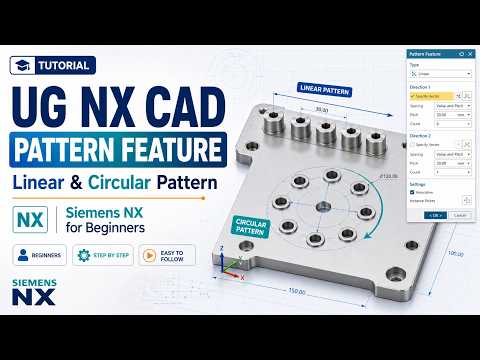
How to Master Linear and Circular Patterns in Siemens NX 3D CAD

When working on complex engineering designs, manually replicating individual features can consume hours of unnecessary effort. Whether you are a student or an industry professional, mastering efficiency tools in modern 3D CAD software is essential for streamlining your modeling workflow. Among these tools, the Pattern Feature in Siemens NX (UG NX) stands out as one of the most powerful capabilities for duplicating geometric elements quickly and accurately.

In this beginner-friendly guide, we will explore how to effectively utilize Linear and Circular Patterns in Siemens NX to elevate your design process.

What is the Pattern Feature in Siemens NX?

The Pattern Feature allows designers to create multiple instances of selected features—such as holes, bosses, or slots—and arrange them in specific geometric layouts. Instead of drawing each element individually, you can define a single master feature and specify the direction, spacing, and quantity for automatic generation. This approach not only saves significant modeling time but also ensures parametric consistency across your entire design.

Mastering Linear Patterns

A Linear Pattern replicates selected features along one or two linear directions. This technique is ideal for creating arrayed components like mounting holes, heat sink fins, or structural ribs.

To create a linear pattern in Siemens NX: 1. Select the feature you wish to multiply. 2. Define the primary direction vector (such as an edge, axis, or datum line). 3. Choose your layout method (e.g., Count and Pitch, Count and Span, or Pitch and Span) and enter the values. 4. Add a secondary direction if you need to create a two-dimensional grid layout.

Mastering Circular Patterns

When designing rotational or symmetrical components—such as wheel rims, gears, flange bolt patterns, or turbine blades—the Circular Pattern option is your best choice. It distributes features evenly around a specified axis of rotation.

To execute a circular pattern: 1. Choose the target feature for replication. 2. Define the center axis of rotation and the base point. 3. Input the total number of instances and the total angular span (e.g., 360 degrees for a full circular array).

Why Pattern Features Matter in 3D CAD

Leveraging automation tools like linear and circular patterns is crucial for anyone looking to excel in 3D CAD design. Utilizing built-in pattern capabilities in your 3D CAD environment drastically reduces manual rework, minimizes design errors, and simplifies future modifications. By mastering these foundational pattern techniques in Siemens NX, you can boost your productivity and build clean, fully parametric models with confidence.

3D CAD
Continue Reading | ความคิดเห็น

Master Ultra-Realistic 3D CAD Animation: Combining SolidWorks and Blender

In today's fast-paced digital landscape, visual representation is everything. Whether you are an engineer showcasing a groundbreaking product design or a digital artist bringing complex mechanical movements to life, achieving high-fidelity visuals is essential. By bridging the gap between precise engineering tools and high-end artistic rendering, creators can transform standard 3D CAD models into photorealistic, cinematic animations.

The Power of SolidWorks Meets the Artistry of Blender

SolidWorks has long been an industry standard for mechanical design and parametric modeling. It provides unmatched precision, allowing designers to build intricate components with exact real-world dimensions and constraints. However, while traditional engineering tools excel at functional accuracy, generating cinematic lighting, lifelike textures, and dynamic camera movement often requires advanced rendering software.

This is where Blender enters the workflow. As a versatile, open-source 3D creation suite, Blender offers industry-leading rendering engines, realistic material shaders, and flexible animation tools. Integrating your 3D CAD designs into Blender opens up endless possibilities for creating studio-quality visuals, complete with accurate depth-of-field, lens flares, and physically based rendering (PBR) materials.

Key Workflow Steps for Ultra-Realism

To turn rigid mechanical assemblies into stunning animations, professional creators rely on a seamless hybrid workflow:

  1. Precision CAD Modeling: Build your assembly in SolidWorks or your preferred 3D CAD software, ensuring every joint, bolt, and moving part is structured logically.
  2. Mesh Optimization: Export your model into optimized formats like OBJ or FBX. Pay close attention to mesh density to balance detailed geometric curves with smooth rendering performance.
  3. Advanced Shading and Texturing: Import the model into Blender to assign realistic surface properties, such as brushed metals, clear glass, or subtle surface imperfections like scratches and fingerprints.
  4. Cinematic Lighting and Motion: Utilize studio lighting setups or HDRI environments alongside smooth camera movement to emphasize the sleek contours and functional design of your mechanism.

Elevate Your Visuals Today

Combining the structural accuracy of CAD software with the visual freedom of modern rendering tools is the ultimate secret to producing ultra-realistic animations. By adopting this powerful workflow, you can create compelling product visualizations, engaging marketing materials, and impressive portfolio pieces that captivate any audience.

3D CAD
Continue Reading | ความคิดเห็น

Popular Posts Today

 
Support : 3Dcadbrowser | Grabcad | 3Dcontentcentral | D | E | F | G
Copyright © 2028. Engineering 3DCad Appication - All Rights Reserved