
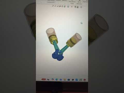
Modern mechanical engineering relies heavily on advanced 3D CAD software to conceptualize, design, and simulate complex mechanical systems before they ever hit the production line. Among the most iconic challenges for designers is modeling an internal combustion engine. In this guide, we will explore how to assemble and animate a classic V-engine mechanism—complete with the crankshaft, connecting rods, and pistons—using SolidWorks.
Understanding the Core Components of a V-Engine
A V-engine features cylinders arranged in two angled banks connected to a single crankshaft. To create an accurate digital model, you must first design or import the core mechanical components:
- The Crankshaft: Converts linear motion into rotational energy.
- Connecting Rods: Link each piston directly to the crankshaft journals.
- Pistons: Reciprocate within the cylinder block to generate power.
Designing a complex mechanism like a V-engine in 3D CAD requires a clear understanding of geometric constraints to ensure every component aligns seamlessly.
Assembling the Mechanism with Mate Relations
Once the individual parts are ready, the real magic happens in the assembly environment. Using SolidWorks mechanical mates, you can define precisely how components interact dynamically:
- Concentric Mates: Align the connecting rod ends with the crankshaft journals and piston pins.
- Coincident and Parallel Mates: Keep the pistons properly oriented inside their cylinder bores.
- Mechanical Mates: Establish proper rotational and linear constraints between interconnected moving parts.
Properly constraining your parts ensures that turning the crankshaft smoothly drives all connected pistons in realistic harmony without causing physical interference.
Animating Your Engine Model
Static 3D models are useful, but motion analysis brings your design to life. By utilizing Motion Studies in SolidWorks, you can apply a virtual motor to the crankshaft. Watching the realistic motion of pistons sliding within a V-configuration allows you to verify clearances, inspect kinematic behavior, and create stunning visual demonstrations of your mechanical concept.
Mastering these dynamic assembly techniques in 3D CAD will elevate your engineering portfolio, whether you are a student, a professional designer, or a 3D modeling enthusiast.
